Goos–-Hänchen effect was an important optical phenomenon. When an optical wave propagates from a denser medium to a thinner medium, the total reflection generates coherent interference. The final propagated wave yields a lateral displacement relative to the incidence wave at the interface. Even though oEffect: An Intriguing Phenomenon from Optics has a coherent effect on the total reflection of a finite-sized wave and an acoustic wave ito Acoustics incoherent with a non-total reflection of different frequency components, recent research shows that there is an analog Goos–Hänchen effect in acoustics.
- Acoustic analogies
- lateral displacement
- transition time
- fluid-solid interface
- water-Perspex interface
- reflection and refraction
1. Introduction
Throughout human history, people have been fascinated by sound and light, by what they saw and heard. Understanding the relationship between optical and acoustic phenomena has been an ongoing scientific endeavor. Analogies between optical and acoustic theories have been mutually beneficial, yielding theoretical advances in both fields. Studies of the analogy between sound and light involved many aspects, including optics, music, mathematics, and physics, and historical discussions have been summarized in the literature [1]. Industrial applications of the acoustic analogs to optics have also been fruitful in recent years, e.g., the acoustic dispersive prism [2], acoustic analogies of high-index optical waveguide devices [3], etc.
Named after German physicists Fritz Goos and Hilda Hänchen, the so-called Goos–Hänchen effect is an important phenomenon in optics [4]. It is noted that when an optical wave is propagating from a denser medium to a thinner medium, the total reflection generates coherent interference; the final propagated wave yields a lateral displacement relative to the incidence position at the interface. This optical effect is critically important in practical applications of optical interfacial-transition, e.g., slow-light processes [5], interfaced-induced superconductivity [6][7][8][9][10][11][12][6–12], material nucleation [13], nanophotonics and optic-electromagnetic applications [14][15][16][17][18][14–18], as well as many practical applications involving media interfaces in acoustics [19][20][21][22][23][24][25][26][27][28][19-28].
Is there a Goos–Hänchen effect in acoustics? Well, there have been temptations of the Goos–Hänchen effect in acoustics, including the studies of a rigid interface between fluid and solid [29], elastic reflector [30], ultrasonic nondestructive inspection [31] [31], and omnidirectionally harmonic incident wave [32][33][34][32-34]. Most of these reported works have been focused on phase shift. Two models have been reported on lateral displacement [35][36][37][38][39][40][41][35-41].
2.
Physical Models
Consider an interface between fluid and solid, where a harmonic P-wave strikes at the interface, which generates the reflected and refracted waves [42], as shown in Figure 1.
To examine the Goos–Hänchen effect in acoustics, the two proposed lateral-displacement models are as follows: (i) a virtual lateral-displacement model (VLDM), where the effective speed is equivalent to the propagation speed of the acoustic wave; and (ii) a real lateral-displacement model (RLDM), where the effective speed is the real speed of the acoustic signal, as shown in Figure 2. The effective propagation speed (either an equivalent propagation speed or the real propagation speed) of the reflected P-wave are dependent not only on the media of the two sides of the interface but also the incident-angle of the P-wave.
In the reported studies, the interface between fluid water and a solid Perspex has been used as a prototype testing system for these models [35].
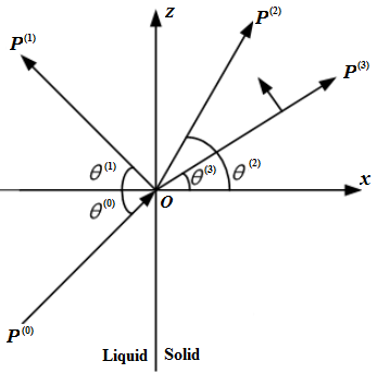
Figure 1. Reflection and refraction of an acoustical harmonic-wave at the interface between a fluid and a solid, where the index m = {0, 1, 2, 3} denotes the incident P-wave, reflected P-wave, refracted P-wave, and refracted SV-wave, respectively.
Figure 2 is a schematic presentation of the reflection paths. For post-critical angle incidence, the reflected P-wave creates a phase shift with respect to incident P-wave. When mapping this phase shift onto the spatial domain, it generates either a virtual lateral displacement or a real lateral displacement. The VLDM (dashed line) has a propagation path T-A-RI. The RLDM (solid line) has a propagation path T-A-B-RR. For RLDM, the incidence point (A) differs from the reflection point (B), which produces a lateral displacement A-B. The amplitude of this lateral displacement varies with respect to the incidence-wave frequency.
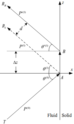
Figure 2. Schematic presentation of the reflection paths: VLDM (dashed line) has an observation point RI and the RLDM (solid line) has an observation point RR.
3.
Lateral Displacement
Figure 3 presents a sample of lateral displacement (Δz), transition time (Δt), and effective propagation speed (v) of a reflected harmonic P-wave at the interface between water and Perspex. The lateral displacement and transition time are positive. The needed time to follow either the VLDM path or the RLDM path is longer than the propagation time in the fluid water, which is a clear indication of the Goos–Hänchen effect in acoustics.
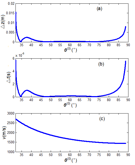
Figure 3. A sample of harmonic P-wave reflected from the interface between fluid water and a solid Perspex: (a) lateral displacement, (b) transition time, and (c) effective propagation speed.
4. Transition Time
The transition time of the acoustic signal reflected from the interface can be used as an alternative measurement for lateral displacement.
To determine a relative time-scale of the transition time along the VLDM and RLDM paths, let’s consider the time deviation from the traditional sliding refraction P-wave model in petroleum acoustic-logging, as shown in Figure 4. For propagation along the path from T to M1 (in water), then to M2 (at the interface), and finally to R (in water), we define the transmission-time as ts. The transmission-time in water along the path T-O, and then O-R is defined as tp. In Figure 2, the transmission-time along the VLDM path is tI and the transmission-time along the RLDM path is tR. Then, the time deviation of the VLDM path from the traditional sliding refraction P-wave model is ΔtIs = tI - ts and the transition time is ΔtI = tI - tp. On the RLDM path, the time deviation is ΔtRs = tR - ts and the transition time is ΔtR = tR - tp.
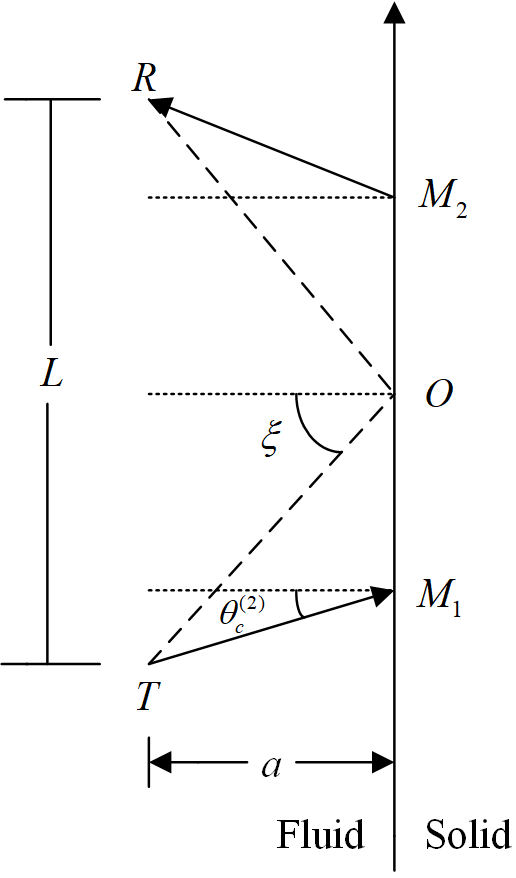
Figure 4. Traditional sliding refraction P-wave acoustic-logging model, where T is the acoustic source, R is the observation position, and ξ is the geometrical structure angle.
Figure 5 shows the calculated transition-time (ΔtI) along the VLMD path and the transmission-time deviation (ΔtIs). It shows that there is indeed a virtual lateral displacement at this interface, which is again a demonstration of the acoustic Goos–Hänchen effect. Along the RLDM path, the calculated results are similar to but slightly different from that of Figure 5, which provides the same conclusion as that of the VLDM path.
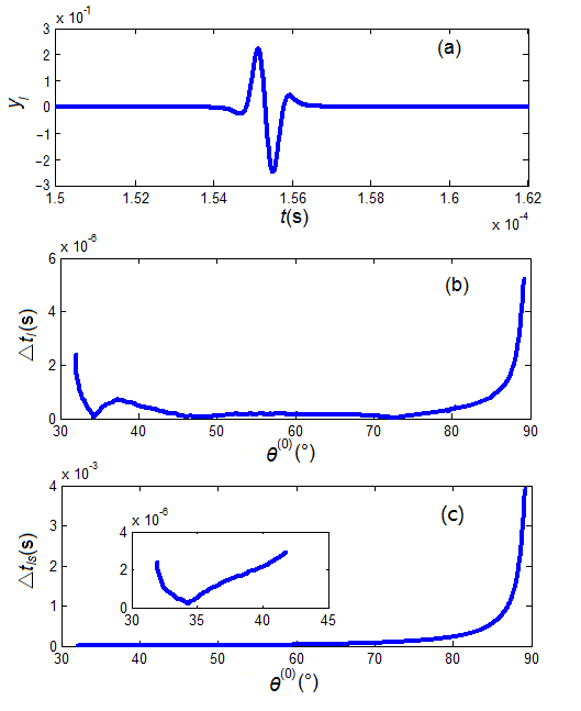
Figure 5 A sample calculation along the VLDM path at the interface between water and Perspex: (a) waveform (yI), (b) transition time (△tI ), and (c) transmission time-deviation (△tIs) from the traditional sliding refraction P-wave model.
5. Additional Questions
In the two lateral-displacement models at the water–Perspex interface, there is clearly an acoustic Goos–Hänchen effect. While this result is exciting, we are still puzzled by the insufficient physical interpretation and unanswered questions.
Foremost, the Goos–Hänchen displacement in optics is a coherent effect of the total reflection of a finite-sized optical beam. The transition of an acoustic signal, as discussed here, is incoherent and is a non-total reflection of different frequency components. It is somewhat unexpected to find the acoustic analog of the Goos–Hänchen effect, where the acoustic wave has such different physical properties from optics. Clearly, an insightful physical explanation is needed to enhance our understanding.
Secondly, the transition time calculated from the VLDM model is different from that of the RLDM model. Even though both models have provided the same conclusion, it is not clear which model is more physically meaningful. Are they both meaningful but in different physical domains?
Finally, the discussion is based on a specific interface system between fluid and solid, i.e., the interface between water medium and Perspex. We are still waiting to see if the discussed result is generic and can be applied universally to all systems.
Overall, the Goos–Hänchen effect is an intriguing topic from optics to acoustics that warrants further investigation. There remain many critical questions, that need to be answered. Until these questions are properly answered, we are unable to provide a tangible conclusion.
References
- O. Darrigol, Centaurus 2010: Vol.52: pp.117–155; pp.206–257.
- H. Esfahlani, S. Karkar, H. Lissek, and J. R. Mosig, Scientific Reports, v6, 18911 (2016).
- F. Zangeneh-Nejad, R. Fleury, Sci Rep 8, 10401 (2018).
- F. Goos, and H. Hänchen, Ann. Phys. 436, 333 (1947).
- C. Lu, X. Hu, L. Shi, Q. Hu, R. Zhu, H. Yang, Q. Gong, Light: Science & Applications. 4(6), e302 (2015).
- Y. Zhong, Y. Wang, S. Han, Y. Lv, W. Wang, D. Zhang, H. Ding, Y. Zhang, L. Wang, K. He, R. Zhong, J. A. Schneeloch, G. Gu, C. Song, Sci. Bull. 61(16), 1239-1247 (2016).
- Q. Wang, Z. Li, W. Zhang, Z.-C. Zhang, et al., Chin. Phys. Lett. 29(3), 037402 (2012).
- J. Jia, Sci. Bull. 60(15), 1368-1369 (2015).
- S. A. Kivelson, Sci. Bull. 61(12), 911-913 (2016).
- F. Zhang, Sci. Bull. 61(16), 1236-1238 (2016).
- Z. Zhang, Y. Wang, Q. Song, C. Liu, R. Peng, K. Moler, D. Feng, Y. Wang, Sci. Bull. 60(14), 1301-1304 (2015).
- Z. Li, F. Wang, H. Yao, D.H. Li, Sci. Bull. 61(12), 925-930 (2016).
- P. Sui, Z. Dai, Sci. China-Phys. Mech. Astron. 58(5), 052002 (2015).
- H. K. V. Lotsch, Optik. 32, 116-137, 189-204, 299-319, 553-569 (1970).
- P. Tournois, IEEE J. Quantum Electron. 33, 519-526 (1997).
- A. Ranfagni, P. Fabeni, G. P. Pazzi, D. Mugnai, Phys. Rev. E. 48, 1453-1460 (1993).
- A. Lakhtakia, Electromagnetics. 23, 71-75 (2003).
- K. J. Resch, J. S. Lundeen, A. M. Steinberg, IEEE J. Quantum Elect. 37, 794-799 (2001).
- L. Fa, M. Zhao, “Network Modeling of Piezoelectric Transducers for Energy Conversion,” Encyclopedia, 2019, v1, https://encyclopedia.pub/item/revision/1ad58669356a9c8d960b505d3fd612f4.
- L. Fa, N. Tu, H. Qu, Y. Wu, K. Sun, Y. Zhang, M. Liang, X. Fang, M. Zhao, Micromachines 10, 804 (2019).
- L. Fa, J. Tang, Q. Zhang, M. Zhang, Y. Zhang, M. Liang, M. Zhao, Front. Phys. 15, 22601 (2020).
- L. Fa, J. Mou, Y. Fa, X. Zhou, Y. Zhang, M. Liang, P. Ding, S. Tang, H. Yang, Q. Zhang, M. Wang, G. Li, and M. Zhao, Frontiers in Physics 6, Article 23 (2018).
- L. Fa, X. Zhou, Y. Fa, Y. Zhang, J. Mou, M. Liang, M. Wang, Q. Zhang, P. Ding, W. Feng, H. Yang, M. Zhao, Sci. China-Phys. Mech. Astron. 61(11), 114321 (2018).
- L. Fa, L. Xue, Y. Fa, Y. Han, Y. D. Zhang, H. Cheng, P. Ding, G. Li, S. Tang, C. Bai, B. Xi, X. Zhang, M. Zhao, Sci. China-Phys. Mech. Astron. 60(10), 104311 (2017).
- L. Fa, M. Zhao, J. Castagna, Y. Liu, L. Wang, Y. Wang, J. Sun, Sci. China-Phys. Mech. Astron. 57, 1-12 (2014).
- Y. Zhao, N. Zhao, L. Fa, M. Zhao, J. of Mod. Phys. 4, 11-18 (2013).
- L. Fa, Y. Tian, W. Xie, and M. Zhao, Chin. Sci. Bullet. 57, 1246-1260 (2012).
- L. Fa, J. P. Castagna, Z. Zeng, R. L. Brown, and M. Zhao, Chin. Sci. Bulle. 55, 2241 (2010).
- M. A. Breazeale, L. Adler, G. W. Scott, J. Appl. Phys. 48, 530-537 (1977).
- A. Atlar, C. F. Quate, H. K. Wickramasinghe, Appl. Phys. Lett. 31, 791-793 (1977).
- R. Briers, O. Leroy, G. Shkerdin, J. Acoust. Soc. Am. 108, 1622-1630 (2000).
- A. Wang, F. Liu, Applied Mechanics and Materials 488-489, 923-925 (2014).
- F. Liu, A. Wang, R. Li, et al. Chin. J. Geophy. 52, 2128-2134 (2009).
- F. Liu, X. Meng, J. Xiao, et al. Sci. China Earth Sci. 55, 852-857 (2012).
- L. Fa, L. Xue, Y. Fa, Y. Han, Y. Zhang, H. Cheng, P. Ding, G. Li, S. Tang, C. Bai, B. Xi, X. Zhang, M. Zhao, Sci. China Phys. Mech. Astron. 60, 104311 (2017).
- L. a and M. Zhao, “Recent development of an acoustic measurement system,” in Understanding Plane Waves; Nova Science Publishers: Hauppauge, NY, USA, 2019.
- L. Fa and M. Zhao, “Recent progress in acoustical theory and applications,” in Understanding Plane Waves; Nova Science Publishers: Hauppauge, NY, USA, 2019.
- L. Fa, Y. Fa, Y. Zhang, P. Ding, J. Gong, G. Li, L. Li, S. Tang, M. Zhao, Sci. Rep. 5, 12700 (2015).
- L. Fa, W. Li, J. Zhao, Y. Han, M. Zhao, J. Acoust. Soc. Am. 141, 1 (2017).
- L. Fa, J. Zhao, Y. Han, G. Li, P. Ding, M. Zhao, Sci. China-Phys. Mech. Astron. 59, 644301 (2016).
- L. Fa, R. L. Brown, J. P. Castagna, J. Acoust. Soc. 120(6), 3479-3492 (2006).
- L. Fa, J. P. Castagna, H. Dong, Sci. China-Phys. Mech. Astron. 51, 823-846 (2008).