ThRecent developments in renewable energy installations in buildings have highlighted the potential improvement in energy efficiency provided by direct current (DC) distribution over traditional alternating current (AC) distribution. Despite the progress and optimal efficiency ofThis is explained by the increase in DC load types and energy storage systems such as batteries, while renewable energy sources such as photovoltaics (PVs) produce electricity in DC form. In order to connect a DC distribution system implementation, there is still no consensus on standardization and regulato the alternating current grid (e.g., for backup, delivering energy storage to the grid) there is a need for a bidirectional inverter, which needs to operate over a wide range of source and load conditions and is therefore critical to the overall system performance. However, DC distribution in buildings is relatively new, with much of the research focused on the control of the DC bus connection between sources and loads, rather than on the grid connection. It has been shown that the DC system performance could vary in terms of efficiency depending onTherefore, this review aims to explore recent developments in bidirectional inverter technologies and the associated challenges imposed on grid-connected DC distribution systems. The focus is on small-scale building applications powered by photovoltaic (PV) installations, which may include energy storage in the form of batteries. An evaluation of existing inverter topologies is presented, focusing on semiconductor technologies, control techniques, and efficiency under variable source and load profile, utilized renewable energy sources, and utility grid integrationconditions. Challenges are identified, as are optimal solutions based on available technologies. The work provides a basis for future developments to address current shortcomings so that the full benefits of DC distribution can be achieved.
1. Introduction
1.1. Background and Motivation
Renewable energy sources, including solar photovoltaics (PVs) and wind turbines, are considered the most dominant solutions to guarantee energy security, with solar PVs outweighing the advantages of other sources in terms of cost and environmental friendliness
[1]. However, in order to maximize the supply of energy from renewable sources, the efficiency of the path from source to load needs to be optimized. For instance, the integration of a photovoltaic (PV) system with a conventional alternating current (AC) distribution system requires an inverter to convert the direct current (DC) electricity produced by PVs into a standard AC grid form. On the other hand, there is an ever-increasing range of domestic appliances and equipment that operate from a DC supply, e.g., computing and audiovisual equipment, cordless vacuum cleaners, etc., but they require an AC/DC rectifier stage to connect to the conventional AC distribution system (mains). In recognition of the improved efficiency provided by DC distribution between a DC source and DC loads (through the elimination of two complementary stages of power conversion), there has been significant growth in the range of appliances configured for supply from a DC distribution system, e.g., cooling, heating, lighting, refrigerator, washing machines, etc.
[2]. Indeed, standards are being developed for DC-configured products under the EMerge Alliance
[3], in which a high DC voltage level of 300–380 V is preferred in terms of distribution capability, lower equipment cost, and simplicity of integration with existing system infrastructure
[4]. It is worth mentioning that such DC appliances correspond to over 60% of the total electricity consumption of householders in the U.S.
[5].
In order to determine the benefit provided by DC distribution, recent studies have analyzed the relative efficiency of AC and DC systems
[6][7][6,7]. Increased efficiency of up to 16% has been predicted for DC vs. AC when a PV installation and energy storage are utilized. A similar level of improvement was reported in
[8] in which an additional energy source, such as a gas engine, was included with PVs, providing increased efficiency of 15%. Even in the absence of a PV source, in
[9], the application of a DC distribution system in an office building was predicted to have lower power losses by up to 14.9% compared to the AC systems when only powered by the grid energy. In the case where renewable energy and energy storage are integrated with the utility grid through DC, optimal efficiency of up to 50% has been predicted for small-scale buildings
[10][11][10,11]. This is encouraging for residential buildings which are likely to achieve self-sustainability compared to commercial buildings
[10], thereby achieving the advantages of net-zero energy, such as resilience and reliability, and sustainability in buildings can be optimized.
However, when a DC distribution system is implemented and integrated with the AC grid, an inverter with bidirectional power flow is usually needed to feed the grid in the case of excess power from the PVs and to supply power from the grid to maintain the DC bus at a nominal voltage when the load demand is higher than PV generation. This compares with standard unidirectional inverters, which are normally used to feed PV energy into an AC distribution system. Bidirectional inverters have been widely used in higher power applications such as energy storage batteries and plug-in hybrid or fully electric vehicles. In electric vehicle (EV) applications, the bidirectional capability may be required to facilitate vehicle-to-grid (V2G) between the grid and the DC bus, although normally, only a unidirectional rectification stage is used to charge the EV battery. However, since EV battery charging has its own specific requirements in terms of battery voltage and charging algorithms, it is not considered further. Instead, this work concentrates on the bidirectional inverters in DC distribution systems integrated into residential buildings.
1.2. Bidirectional Inverter Challenges
The interface between the DC bus and the AC grid is crucial because it can reduce the operation efficiency and stability of the overall system performance. Therefore, methods for increasing the efficiency of bidirectional inverters have received considerable attention because they relate to the return on investment of the DC system. High efficiency over a wide range of power levels has significant benefits for increasing DC system efficiency in buildings, especially small-scale domestic installations, where there is usually a mismatch between periods of PV production and energy consumption
[12][13][14][12,13,14]. This is less relevant for commercial buildings.
Transformerless topologies are widely used to reduce losses (and costs) associated with transformers in isolated topologies. However, it is important to highlight that due to dynamic coupling between the shared AC and DC ground in a transformerless solution, the parasitic capacitance of PV panels causes a leakage current. This has a negative impact on the inverter efficiency and needs to be minimized to avoid significant loss
[15]. The effect varies depending on the common mode voltage (CMV) across the parasitic capacitor, and therefore, modulation strategies can alleviate the issue
[16]. Other solutions are discussed in more detail below.
High leakage current may lead to the additional distortion of the output grid current caused by high-frequency operation, where the utility grid standardization needs to be in compliance with the safety regulations of electrical equipment. On account of this, an EMI filter is required to attenuate the grid current to an optimal level of quality on the AC side in the case of inverter mode. However, while the ground of the AC and DC sides are shared through the distribution plant in the building, the common-mode (CM) and electromagnetic interference (EMI) noise-related issues will cause an impact on the DC side. The DC-bus voltage, as well as differential-mode (DM) and (CM) noise, must be kept within a small-voltage ripple to provide improved power quality, ensure reliable load operation, and reduce significant loss in the system. Different filtering schemes to address this are described later. It is shown that the additional number of passive components, as well as the complexity of the associated control approach, would reduce the efficiency of the design. As a consequence, a trade-off must be made in the development of a suitable EMI filter in order to reduce the aforementioned concerns.
Given the strong correlation between the leakage current and the EMI filter, it should be noted that the range of current that the filter inductor needs to support is another challenge due to the potential nonlinear characteristic of its core material. As a result, the tracking accuracy of the employed current controller to set the required grid current may be influenced by the inductor current ripple. Moreover, errors in zero-crossing detection for grid synchronization could be introduced due to insufficient magnetization of the inductor core material which has an impact on the grid current. This effect is important for both inversion and rectification modes in a grid-connected inverter. Indeed, in rectification mode, power factor correction (PFC) is required to reduce the consumers’ load demand for reactive power. In addition, the harmonic regulation has to be fulfilled according to the required grid code. It is worth noting that the response to different weather conditions of renewable energy sources such as PVs can cause a wide voltage variation on the DC side of the bidirectional inverter. Under this circumstance, the authors of
[17] offer buck/boost maximum power point tracking (MPPT) to mitigate the sudden change of voltage and associated stress applied to the DC bus interfaced with a grid-connected inverter. This is important to ensure that the bidirectional inverter supplies local load conditions as well as to the grid, efficiently and reliably. The power flow of the bidirectional inverter needs to be maintained based on the DC-bus voltage when subjected to variable source and load conditions
[18]. The control capability also has to assure the stability of the entire system when subjected to a certain level of load demand due to shared power supply either from renewable energy or the grid. Moreover, the DC bus needs to be regulated at a nominal voltage to enable the operation of the battery charge controller and a reliable supply of DC system. On the other hand, the power delivered by the DC-bus in case of excess power from PVs has to meet the standard power regulations of the grid
[19][20][19,20].
2. DC Distribution System Configurations
With the development of efficient DC distribution systems in buildings in recent years, it has commonly been assumed that the combination of different energy sources could enhance performance. However, it has been shown that the DC system performance could vary in terms of efficiency depending on load profile, utilized renewable energy sources, and utility grid integration
[10].
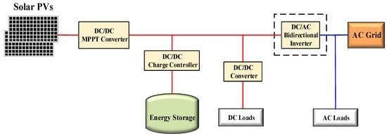
Figure 1 illustrates a general schematic configuration of DC distribution systems in buildings, including renewable energy sources (PV in this case), energy storage, and a mix of AC and DC loads
[21][22][23][24][24,25,26,27]. The system contains a power optimizer known as a maximum power point tracking (MPPT) to maximize the PV output power under different weather conditions
[25][28]. In addition, a step-up/down DC/DC power converter is implemented for charging/discharging the energy storage and to control the power flow to regulate the voltage level of the DC bus.
Figure 1.
Schematic configuration of DC distribution systems integrated with a grid and a backup system.
The integration of grid power is required to assure the continuous operation of the system in supplying the DC loads in the case of insufficient power, either from renewable energy sources or energy storage. However, there are some configurations of DC systems that do not employ renewable energy sources, in which energy storage and/or a fossil fuel-based generator and grid power are utilized instead. Under these circumstances, energy storage could be beneficial to address the peak saving and ensure the security of supply, or for applying demand-side management when there are no alternative energy sources. On the other hand, regardless of the importance of energy storage, it is not always included in DC system configurations.
Despite the progress and optimal efficiency of DC distribution system implementation, there is still no consensus on standardization and regulation. The EMerge Alliance has developed a standard for 24 Vdc distribution for low power loads within inhabited areas, and several certified infrastructure solutions have successfully shown compliance with this standard
[2]. However, 24 V is not compatible with typical battery and inverter voltages. In addition, the alliance has recommended the implementation of a 380 Vdc standard for use in higher power applications such as data centers and central telecom offices
[2]. This standard might pave the way for DC distribution in residential and commercial applications at voltages greater than 24 V, which would be advantageous for both sectors. As a result, the academic literature on such systems integrated into buildings has revealed the emergence of several contrasting themes in terms of DC bus configuration and voltage level
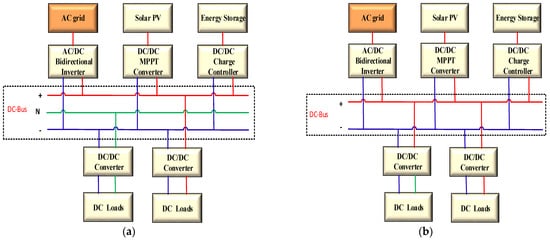
[26][27][28][29,30,31]. The purpose of a DC-distribution system is to eliminate some of the integrated conversion stages to increase the overall distribution system efficiency. However, depending on the range of loads to be supplied, there are two dominating DC bus structures, bipolar and unipolar, as presented in
Figure 2. The principle of a bipolar type is that the DC bus has three lines, positive and negative lines, +Vdc, −Vdc, and the middle line is a neutral line
[29][30][31][32,33,34], to allow the supply of loads with two available voltage ranges, as depicted in
Figure 2a. In addition, the system has robust reliability to guarantee that loads are fed when an electrical fault occurs in either line
[32][35]. Moreover, with a bipolar structure, the neutral point is grounded, which considerably reduces the line-to-ground safety risk by significantly reducing the highest allowable DC-line voltage relative to the ground.
Figure 2.
The structure of (
a
) bipolar DC bus, (
b
) unipolar DC bus.
Figure 2b shows the unipolar DC distribution system with one consistent voltage level, represented by the use of two lines, one labeled “+Vdc” and the other “−Vdc”. The unipolar structure is more suitable for systems with low power loads due to the cost saving associated with reduced wiring compared to the bipolar type
[33][36]. However, the lower voltage level of unipolar systems may limit the efficiency that can be achieved regardless of its cost benefits
[34][37]. In terms of these DC bus structures integrating with the grid through a bidirectional inverter, there is one study implemented with a bipolar type (
Figure 2a)
[35][38]. This approach usually experiences additional costs in terms of control structure and computation, and ultimately the overall benefit is slightly higher when unipolar is used.
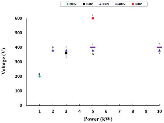
A comparison of the existing empirical literature on DC-bus voltage versus power integrated with a single-phase bidirectional inverter is illustrated in
Figure 3. Based on the results, it may be observed that once the power level is high, the voltage typically corresponds to that of the peak mains, i.e., √2 times the root mean square (rms) voltage. It can be seen that the majority of the DC bus voltage levels fall somewhere in the region of 380 to 400 V. High-voltage operation (i.e., 600 V) is applied in cases where two voltage levels (600 V/300 V) may be required, allowing for the adaptability of DC load connection. Nevertheless, it is possible to conclude that the high power and voltage level (i.e., 10 kW and 600 V) is not appropriate for residential buildings from a safety perspective, despite the fact that it provides a high level of efficiency.
Figure 3. DC-bus voltage level integrated with a bidirectional inverter. a—
[36][37][39,40]; b—
[38][41]; c—
[39][42]; d—
[40][43]; e—
[41][44]; f—
[42][43][44][45][46][47][45,46,47,48,49,50]; g—
[48][49][50][51][52][51,52,53,54,55]; h—
[35][53][54][38,56,57]; i—
[55][58].