1. Overview
In general, voids are nucleated in the vicinity of stress concentrators on a microscopic scale
[1]. In the literature, the most frequently mentioned mechanisms include the formation of voids at the intersection of the slip bands
[2], at the grain boundaries
[3], at twin boundaries and at vacancy clusters
[4], but most importantly around inclusions and precipitates
[5][6][7].
2. Nucleation with No Particles Involved
In the absence of material discontinuities, the formation of voids is observed as planar slip band decohesion or grain boundary decohesion (homogeneous nucleation). One of the first widely known studies in which the participation of dislocations in the formation of voids was experimentally confirmed was developed by Gardner et al.
[3], who noticed that the dislocation structures in iron and beryllium crystals evolved into cells at high strains. The boundaries between individual cells were characterised by sufficient surface energy to create a void, even in the absence of other internal stress concentrators.
The observations of the development of voids in the Nb-Cr-Ti alloy
[2] showed that the voids formed in this way are characterised by a flattened shape.
The concept of void nucleation as a result of vacancy condensation and the presence of dislocation boundaries has been known for a long time
[8][9], but only modern research techniques allowed for a better understanding and documentation of this phenomenon
[10]. For example, in
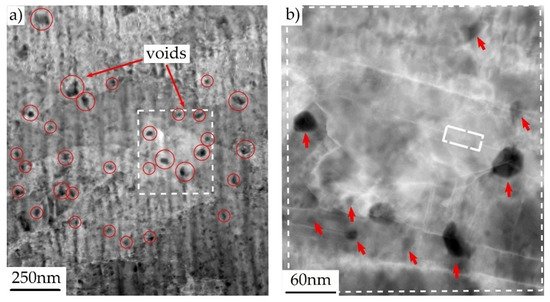
[11], by investigating the fracture mechanism of copper containing copper oxide particles, it was found that the voids are first nucleated at the nanoscale, most often without any relation to the presence of the second-phase particles. An example of a photograph of nanovoids, made with the use of the high-angle annular dark-field scanning transmission electron microscopy (HAADF-STEM), is shown in
Figure 1.
Figure 1. (
a) HAADF-STEM image presenting nanoscale voids (black areas) in copper subjected to tension (plastic strain); (
b) Enlargement of the boxed area in (
a), from
[11]. White rectangle in (
b) indicates the twin boundary.
In the next stage, only a small quantity of the nanovoids grew to the microscale, contributing to the initiation of cracking. It was noted that all microscale voids were associated with a dislocation boundary. By carefully analysing the microstructure of the material in the neck area, the authors distinguished three basic groups of microvoids, depending on their location and the mechanism of formation, namely: (i) voids related to intragranular, inclusion-free dislocation boundaries; (ii) voids associated with the inclusion-free intersection between one or more dislocation boundaries and one or more grain boundaries; (iii) voids associated with an inclusion intersected by a dislocation boundary.
As mentioned before, voids can be initiated by grain separation. This mechanism is favoured by the following conditions: high share of the hydrostatic stress; small value of the void spacing to void diameter ratio; and high value of the precipitate-free zone (PFZ) thickness to void spacing ratio
[12].
3. The Role of Second-Phase Particles
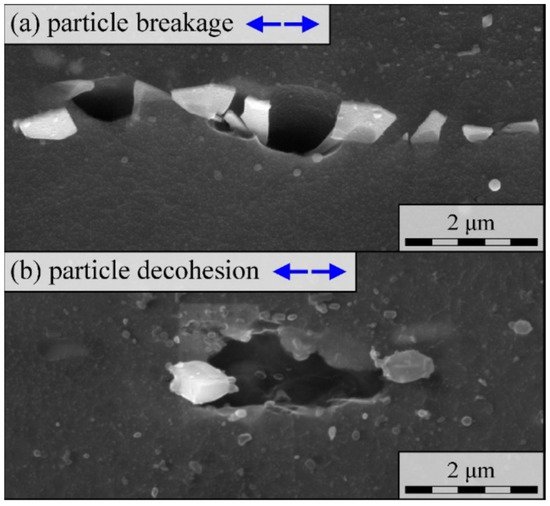
In technical alloys, voids are often initiated by the failure of second-phase particles, randomly distributed over the material matrix (heterogeneous nucleation). The presence of a hard particle locally limits elastic and plastic deformation of the matrix, which in turn causes local stress concentration. With the increase in plastic strain, the stress value also increases, which ultimately leads to the particle cracking or its separation from the matrix
[13]. As the result, a void is formed (
Figure 2).
Figure 2. Two mechanisms of void nucleation in AZ31 magnesium alloy: (
a) Particle fragmentation/fracture; (
b) Matrix–particle separation
[14].
The occurrence of one of the two mentioned mechanisms depends largely on the mechanical properties of the matrix and the particle (strength, ductility) and the strength of the matrix–particle interface. In general, the phenomenon of particle separation is primarily observed in relatively soft, ductile matrices. However, high yield stress and hardening exponent of the matrix as well as the high particle stiffness promote particle cracking.
Moreover, the nucleation mechanism depends on the particle geometry (size, shape) and its orientation with respect to the direction of the principle tensile stresses. Larger particles usually break, as do elongated particles parallel to the principal stress direction. In practice, engineering materials have different void populations; therefore, both mechanisms occur simultaneously. The local stress state is also of great importance, namely the predominance of normal stress over shear stress, which most often forces the particle fracture
[15][16].
Due to the heterogeneous stress state changing with time, the nucleation of voids is continuous across the entire range of plastic strain. In other words, the development of microdamage includes the simultaneous growth and coalescence of existing voids as well as the nucleation of new ones
[17].
Among the experimental studies, the process of nucleation of voids and microcrack formation by fracture of silicon particles in Al-Si alloys is relatively well-documented. The most important results described in the literature are summarised in
[18]. As shown in
[19][20], cracking of silicon particles and their separation from the matrix were observed already at strain values of 1–2%, while the quantity of damaged particles increased linearly with the increasing strain
[21]. According to the results of observations described in
[22], a maximum of 10% of the particles were damaged in the samples subjected to tension or compression. In general, larger particles crack first
[23], which is often explained by a greater probability of internal defects in this type of particles. Smaller-sized particles tend to detach from the matrix, initiating voids.
As noted in
[21], the phenomenon of fracture of silicon particles in the Al-7Si-0.4Mg alloy subjected to tension and bending occurs mainly in the case of elongated particles. The authors also analysed the structure of the alloy deformed to failure. In the areas with a homogeneous deformation (a few mm from the fracture surface) between 3 and 10% of the Si particles cracked. However, in the immediate vicinity of the fracture surface, the proportion of fractured particles locally increased to about 15–20%. In the coarser structures, the fracture of the particles was sudden and occurred at low strains. The development of microdamage in the finer structures was gradual.
4. Estimating Particle Strength
To understand the phenomenon of void nucleation by fracture of the second-phase particles, it is important to estimate their mechanical properties, especially strength. The first and best-known attempts were described in
[24][25]. In
[25], the microscopic maps of the locations of cracked and separated MnS inclusions were compared with the numerically determined stress and strain distributions, which gave rise to assessment of the critical fracture stress of MnS particles of about 1120 MPa. Additionally, in a similar manner, the critical stress of separation of the MnS particle and the matrix was determined, where the stress value was about 810 MPa.
A similar approach was used in
[26], but this time the X-ray technique was used to assess the particle deformation. The tests were carried out on a sample made of an aluminium alloy, subjected to pure bending. Using the X-ray method, the strain values of silicon particles were determined, and then the stresses in the particles were determined as a function of the measured strains.
The typical research methods used so far did not take into account the internal defects of the particles; therefore, the obtained results are not precise.
The significant progress made in recent years in the field of methods of microstructural materials testing allowed for a more in-depth analysis of this issue. An interesting attempt to determine the strength of silicon particles in the A356 aluminium alloy is described in
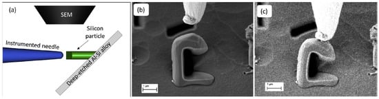
[27]. In order to expose the silicon particles, the ground surface of the sample was subjected to deep etching with a mixture of phosphoric, acetic and nitric acids. As a result, the particles to be tested were exposed to a height of several dozen micrometres. In the next step, using the focused ion beam (FIB) method, the geometric notch of the selected particles was cut. The prepared particles were subjected to an eccentric compression test in which the load was transferred to the particle by a tungsten needle. The test scheme is shown in
Figure 3. The entire course of the process, up to the particle fracture, was recorded using a scanning electron microscope (SEM) with the video recording. In the next stage, based on the values of the measured force, the evaluation of the stress values in the particle was performed, using the simplified analytical method and with the use of the finite element method (FEM). For the defect-free particles, the particle strength was determined to be around 16 GPa. Detailed visual inspection of particles using SEM, combined with FEM modelling, made it possible to evaluate the effect of different types of particle defects on their strength. It was found that the presence of defects can reduce the strength of the silicon particles to 2–3 GPa.
Figure 3. Strength test of silicon microparticles in A356 aluminium alloy: (
a) Scheme of the micromechanical test; (
b) C-shaped particle and the tungsten tip before test; (
c) Last frame before particle fracture, from
[27].
The article
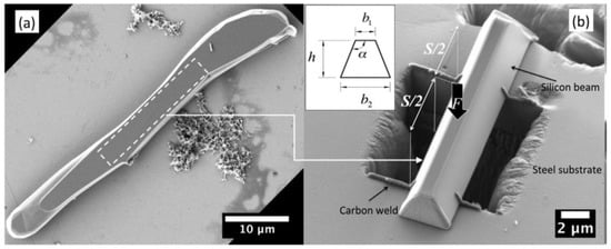
[28] also provides an example of particle strength assessment by means of a microscopic three-point bending test. First, the silicon particles were extracted from the Al-Si alloy by dissolving the aluminium matrix. Then, after cleaning and selecting the particles, microscopic beams were cut from them using the above-mentioned FIB technique. The beam prepared in this way was placed on a steel base with a cut-out hole and subjected to load.
Figure 4 illustrates the tested sample. The results obtained during the experiment were compared with the results of analytical and numerical calculations, which resulted in determining the strength of silicon at the level of about 9 GPa, assuming no particle defects.
Figure 4. (
a) Eutectic silicon particle extracted from the Al-Si alloy; (
b) Microscopic three-point bending specimen prepared from the particle in (
a), from
[28].
A significant technical problem during the microscale strength tests is the measurement of deformations and stresses. Recently, the Raman spectroscopy technique offers a wide range of analysis of stress values on a microscopic scale, and thus also the evaluation of particle strength. The Raman effect is related to inelastic light scattering. After filtering, the light scattered on the sample goes to the spectrometer, which records its spectrum. The spectrum is presented as a function of the Raman shift, defined as the difference between the frequency of the scattered light and the input light
[29]. In materials science, spectrum analysis enables the recording of the stress values, especially in the case of uniaxial stress states. However, the authors of
[30] present the methodology of plane stress analysis in Si wafers on a microscopic scale.
A more complex analysis is discussed in
[31], where the stress state in eutectic silicon particles in the Al-Si alloy was analysed. The alloy was tested in as-received condition under uniaxial loading. Cracking of silicon particles was observed already at the stress value of 600 MPa. Importantly, the use of Raman spectroscopy enables the assessment of the effect of particle size and its neighbourhood on the strength.
As already mentioned above, the second mechanism of void formation involves the decohesion of the matrix and the second-phase particles. Due to technical difficulties in a detailed, experimental study of this phenomenon, there are relatively few works of this type. Thus, numerical analyses are of particular importance. The solutions described in the literature are most often theoretical in nature. For example, in
[32][33][34] a hypothetical aluminium matrix–silicon particle interface strength was determined in the range of about 4–7 GPa in tension, while the shear strength was only about 300 MPa. As this research deals primarily with experimental research, these issues will not be described in detail here. More information on the simulation of this phenomenon, and the use of cohesive models, can be found in
[35][36][37][38].
5. Effect of Martensite Cracking in DP Steels
As it has been shown in many studies, for example
[39], the mechanism of void formation in dual-phase (DP) steels is only slightly based on the fracture and separation of the second-phase particles, because the fracture of martensite plays the most important role. The development of microdamage of DP1000 steel subjected to tension was analysed in detail in
[39]. Strength tests were carried out inside the scanning electron microscope (SEM) chamber and stopped at regular intervals, each time photographing the microstructure of the material in the selected area. Cracking of the particles was observed at overall small strain, of the order of 2%. With the increase in plastic deformation, the voids created in this way grew, but no crack development in its vicinity was observed. As the strain value was increased further, the martensite phase cracked. Due to increasing deformation, the crack turned into a void, which, being a stress concentrator, became the cause of crack propagation in the ferrite. The high intensity of this phenomenon accounted for its dominant role in the failure of DP1000 steel.
Using advanced research methods, the authors of
[39] attempted to estimate the local values of strains and stresses accompanying martensite cracking and void initiation. The obtained photographs of the microstructure were processed using the digital image correlation (DIC) technique. The photograph of the undeformed structure was divided into subset windows, then an algorithm was applied to track these areas in the photographs of the deformed structure. The results obtained in this way made it possible to determine the vectors of displacements and local deformations. Further, the experimentally determined values of displacements were used as boundary conditions in the finite element method (FEM) model of the tested sample, which allowed for the estimation of martensite cracking stress at the level of about 1700 MPa.
The dominant role of martensite cracking in the formation of voids in DP steels, mainly of the coarse structure, was also emphasised in
[40]. This is the leading mechanism at low strains. At a later stage, voids were formed mainly by the decohesion of ferrite and martensite. The latter mechanism dominated in steels with the finer structure in the entire range of deformation. The occurrence of the decohesion is mainly attributed to the lower deformability of martensite.
Observations of martensite cracking in DP600 steel under uniaxial tension at low strain values were also described in
[41], although as the authors point out, the importance of this mechanism in the entire process of void nucleation is not great. The process of fracture and separation of second-phase particles led to the formation of a few voids, which, however, were characterised by large dimensions, and therefore their area fraction was significant.
The dominant mechanism for the formation of voids was, as in
[42], decohesion at the interface between ferrite and martensite, observed in the entire range of deformation of the tensile sample. The voids were initiated mainly at the interfaces perpendicular to tensile stresses and enlarged along the ferrite grains. The authors of
[41] also noticed that with the increase in strain, the mean size of the voids decreased, which indicates a high intensity of nucleation of new voids also immediately before failure.
The authors of
[43] drew similar conclusions. While examining the development of microdamage in DP600 and DP800 steels under uniaxial tension, it was noticed that at low strain, the void initiators were the globular aluminium oxide inclusions, but with higher deformations the voids were formed near to the ferrite–martensite interfaces as well as in the ferrite matrix and close to martensite islands.
6. Quantitative Description of Void Nucleation
Regardless of the single void nucleation analysis, it is important to evaluate the void nucleation globally, determining the number of nucleated voids as a function of remote strain and the location of the analysed area. In this case, it is particularly important to continuously track changes in the microstructure of the material throughout the deformation range up to the failure.
In recent years, the widespread use of the X-ray microtomography method gave great opportunities in this regard, and has contributed to a much better understanding of the phenomenon of failure and void development
[44][45].
For example, in
[46], the tomography method was used to assess changes in the microstructure of JIS SUM24L free-cutting steel under uniaxial tension. The tests were carried out on tensile specimens subjected to uniaxial stress state. The tests were interrupted at various stages, each time taking tomographic photographs of the microstructure in one selected area. In order to precisely determine the value of strain, especially after necking, changes in the width of the specimen were recorded using tomographic images. As part of the microtomographic research, in the first step, the region of interest (ROI) was distinguished, along with the voids present in the unstrained material. The photographs were then binarised, indicating base material and voids. In the next stage, a 3D labelling algorithm was applied to the binarised images, and then the volume and position of each of the detected voids was determined. In this way, over four thousand voids and the second-phase particles were marked in the ROI, which allowed for their tracking in the entire range of given deformation.
A separate issue was the development of an algorithm that allows for tracking each of the voids in subsequent stages, with increasing values of strain. The adopted procedure included the determination of a transformation matrix that was calculated by minimising the sum of distance difference between corresponding pairs of objects detected in subsequent stages of loading. Due to the heterogeneity of deformation and the different quality of individual photos, the obtained results were not fully accurate, hence the matching probability parameter
Mp was introduced into the analysis. The algorithm developed in this way took into account the translation and rotation of the voids related to the occurrence of plastic deformation. A detailed description of the voids tracking algorithm is presented in
[47][48].
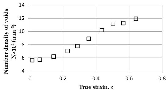
The results of the observation of microstructure changes indicate that the nucleation of voids was continuous throughout the analysed range of deformations, up to failure. This phenomenon is well illustrated by the graph in
Figure 5, where the number of voids in the unit volume [mm
3] of ROI was determined as a function of true strain. From the very beginning, a constant increase in the number of voids is visible. Just before failure, one can see a flattening of the curve, which seemingly means a reduction in the intensity of void nucleation at this stage. In fact, as noted by the authors of
[46], nucleation of voids is still present; however, at this stage, the ductile fracture process is controlled primarily by the void coalescence phenomenon, which explains the flattening of the curve in
Figure 5.
Figure 5. Experimentally determined relation between density of voids and plastic strain in JIS SUM24L free-cutting steel, from
[46].
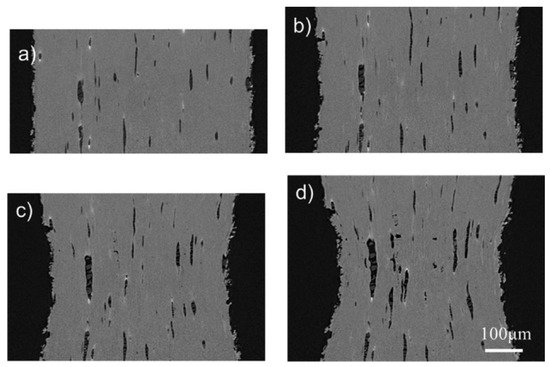
Figure 6 presents tomographic cross sections of ROI, made at different strains. The vertical axis in the individual figures is equated with the direction of loading. Dark areas represent voids, while lighter areas represent the matrix. In Figure 6b (with the strain 0.23), the neck is clearly visible.
Figure 6. Free-cutting steel (JIS SUM24L grade) microstructure at different strains: (
a) 0; (
b) 0.23; (
c) 0.50; (
d) 0.64, from
[46].
Detailed analysis of the individual pictures shows that the nucleation of voids occurs primarily at the interface between the matrix and the particles. The voids are also initiated at the places where the particles of the second phase break. As can be seen from the comparison of the subsequent photographs, some voids seem to disappear as the strain increases. This is due to their rotation and displacement, because the strains are not uniform throughout the tested sample. The void-tracking algorithm described above allowed for the inclusion of this phenomenon in the void development analysis.
Additionally, on the basis of the obtained results of tomographic examinations, changes in the volume and diameter of voids as a function of plastic strain were determined. While, as predicted, the total volume of the voids in the sample increased with increasing strain, the mean diameter of the voids was almost constant, regardless of the strain level. The authors of
[46] indicate the nucleation of new small voids at higher strain levels as a possible reason.
The authors of
[49] also emphasised the key role of small voids in the initiation of fracture. Using the 4D X-ray microtomography technique (3D + time), changes in the microstructure of SA508 steel were analysed in the entire range of tensile strains up to failure. It was observed that large Al
2O
3 and MnS
2 particles (with sizes ranging from several to tens of micrometres) cracked or separated from the matrix at zero values of plastic strain (elastic range). Considering the fact that such particles were scattered and spaced far apart, the voids they initiated did not coalesce, and therefore their contribution to the fracture initiation was insignificant. On the other hand, the elongation of voids along the tensile axis was observed, but the their contraction in the perpendicular direction was not significant. Moreover, the rotation of the elongated voids took place as a result of the increase in the value of shear stresses after the formation of the neck.
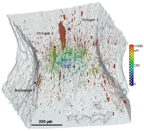
On the contrary, small particles of cementite (with a size of the order of 100–500 nm) detached from the matrix when the remote strain of the order of two was achieved. The initiation of small voids was, however, sudden. A large accumulation of small voids favoured their coalescence, which led to formation of a crack. The microtomographic image of the microstructure of the sample before failure is shown in Figure 7. In the central part of the region of interest, a cluster of small voids initiating a crack is clearly visible.
Figure 7. Microtomographic 3D image of the distribution of voids in SA508 steel, at the onset of failure, in the central part a cluster of small voids initiating a macroscopic defect is present, from
[49]. The colour scale indicates the distance between void and sample centre.
Larger elongated voids predominate at a greater distance from the centre of the sample. The two largest voids (marked in the figure as stringer 1 and 2) were formed from an agglomerate of particles. Additionally, the researchers carefully analysed the void nucleation around the inclusion marked as “inclusion 1” in Figure 7, indicating the mechanism of matrix–particle decohesion.
7. Effect of Stress State on Void Nucleation Intensity
In the previously mentioned work
[1], the influence of the type of load on the intensity of void nucleation was determined.
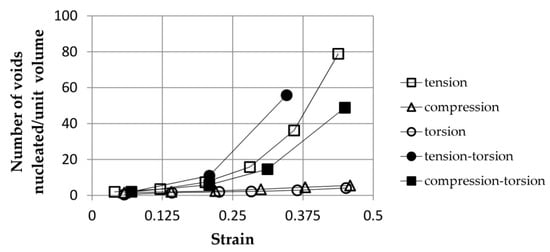
Figure 8 illustrates an exemplary dependence of the number of nucleated voids per unit volume of the cast Al-Si-Mg sample as a function of strain for various loading conditions. The results were obtained using the proprietary analytical void nucleation model. The lowest intensity of void nucleation was obtained for compression and torsion. As expected, among the simple load cases, the voids in the sample subjected to tension showed the highest nucleation intensity. The simultaneous action of tension and torsion resulted in the most intense nucleation of the voids.
Figure 8. Effect of the loading type on the intensity of void nucleation in cast Al-Si-Mg alloy as a function of strain, based on
[1].
Regardless of the above, the authors of
[1] defined the material constants of void nucleation for simple loading conditions (tension/compression, torsion).
Recently, the authors of
[50] conducted a thorough experimental analysis of the impact of the stress state on void nucleation in DP780 and CP800 steels. In order to obtain different components of the stress state, various strength tests were carried out: simple shear, hole tension, v-bending and biaxial tension. In each case, the tests were stopped, recording the material microstructure in the region of interest, using microtomography. Nucleation intensity was measured as the average number of nucleated voids in 1 mm
3 of material in the process zone. At failure, the highest number of voids (about 30,000/mm
3) was observed in the biaxial tension specimens. In the case of hole tension, this value was much lower and ranged from about 9500 to 18,000, depending on the material tested. The specimens subjected to shearing were characterised by the lowest nucleation intensity, i.e., at failure, values between 3000 and 4000 voids in 1 mm
3 of material were recorded.
One of the most frequently analysed issues related to the dependence of void nucleation on stress state is the influence of stress triaxiality T on the value of the strain needed to initiate the void. Stress triaxiality T describes the effect of the spherical component of the stress tensor (hydrostatic tension or compression) and is defined as the quotient of the mean stress (arithmetic mean of the principal stresses) and the Huber von Mises stress. The works published so far, for example,
[51][52], unanimously indicate that the increase in triaxiality (increase in the hydrostatic pressure share) is accompanied by an exponential decrease in the value of nucleation strain.
The author of
[53] drew similar conclusions, at the same time indicating the large influence of the Lode parameter on nucleation and the growth of voids. The Lode parameter takes into account the influence of the third stress tensor invariant. According to Yu
[53], the value of the Lode parameter does not significantly affect the value of the void nucleation strain; however, it plays an important role, as interfacial cracks nucleate from different positions for different Lode parameters and propagate in different patterns. This is due to the fact that the Lode parameter changes the principal stress distribution, even at constant triaxiality.
Han et al.
[54], studying the development of voids in QP980 steel under shear load, noticed that a large number of small voids (less than 5 μm in size) was formed at phase interfaces. In turn, a few microvoids generated from inclusions had more than 5 μm.
The phenomenon of the development of voids under shear was also analysed in detail by the authors of
[55], also indicating the low intensity of nucleation in these conditions. The combination of microtomographic tests with FEM simulation allowed for the determination of the mechanism of ductile fracture of FB600 steel, initiated by separation of the matrix from CaO particles. The voids created in this way grew towards the largest local deformations, forming microcrack-like defects. As noted, a shear-band type of failure was formed on the microscopic scale even with a small volume fraction of voids, of the order of 0.015%. The void volume fraction measured before failure did not exceed 0.1%.
In recent decades, computer simulations have made a huge contribution to understanding the phenomena of void development
[56]. As this research focuses primarily on experimental observations, the review of FEM results will not be discussed in detail here. However, it is worth paying attention to molecular dynamics simulation
[57][58], which offers new possibilities compared to traditional continuum solutions, as it enables material modelling at the atomic level. For example, in
[59], the mechanism of decohesion of the AlCu
2 particle and the aluminium matrix was analysed. In the first stage, the breaking of the bonds between single-inclusion and matrix atoms was observed, which initiated the particle separation. In the next stage, the crack grew steadily, with no dislocation involved. The fracture development in this case was driven by the lattice trapping phenomenon. After the fracture reached a critical size, nucleation of Shockley partial dislocations at the crack tip was observed. Then, the dislocations moved from the particle towards the matrix, whereby the rate of crack propagation increased suddenly, leading to the complete separation of the particle and the matrix. The authors called this stage of separation
dislocation-mediated delamination.