Your browser does not fully support modern features. Please upgrade for a smoother experience.
Please note this is a comparison between Version 2 by Jessie Wu and Version 1 by Ajit Behera.
Additive manufacturing is a technology of transforming a 3D prototype to a physical one directly by successive addition of the required material in a layer-by-layer manner. This technique helps to manufacture the turbine blade which is the revolution of green technology for high temperature engine parts.
- additive manufacturing (AM)
- turbine blade
1. Introduction
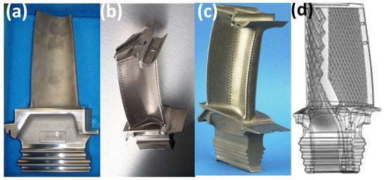
Initially, the technology was aimed at making prototypes of the design as quick as possible and was known as rapid prototyping (RP). Eventually, the scope of RP extended to tooling as well as the manufacturing of parts and products. Today, AM has become an integral part and an important contributor to Industrial Revolution 4.0. The fabrication of functional prototype can sometimes take up to several months as engineers have to design and produce tooling such as molds. This can be reduced by considering AM, where the processing time can be reduced to more than 50%. The best example would be the development of turbine blades at Siemens in 2017 [3][1]. By incorporating 3D printing to develop and test functional prototypes of gas turbine blades, the development and validation time for the component was significantly reduced from two years to just two months. The other key benefits of AM that make it a choice of manufacturing in the case of critical applications are the design freedom of AM, reduced wastage of material compared to subtractive manufacturing, and significant weight reduction in the parts by the application of principles of ‘Design For Additive Manufacturing’ (DFAM). Such contributions are essential for aerospace applications. Through the application of DFAM principles, part consolidation can be achieved. Such parts are made in solitary constructions by the consolidation of structural and functional parts. Incorporating parts in this way reduces the number of hurdles in assembling these complicated designs. Some of the literature [4][2] has shown this result in a report in which 855 single parts were combined into 12 parts. As a result, it significantly reduced the weight by 45 kg, a 20% improvement in fuel consumption, resulting in a 10% increase in power output, greatly simplifying engine maintenance. The reduction in material waste was ensured by the application of DFAM and this exact material waste reduction promoted the decrease in cost production [5][3]. As a consequence, there has been a shift toward additive manufacturing for the production of complex engine parts and components including turbine blades. The overall ease in assembly simplifies the maintenance of these engines, leading to benefits associated with the higher availability of spare parts. AM allows for the design of different types of inbuilt cooling ducts or parts inside the turbine blade. Figure 1 shows various types of AM processed turbine blades as the design approach is incompatible with many conventional manufacturing techniques due to the constraints for producing the optimized design.
2. Selective Laser Sintering (SLS) as an Initial Powder Bed Fusion Process
During the 1980s, with the support of DARPA, Dr Deckard and Dr Beaman of the University of Texas at Austin developed and patented the additive manufacturing technique of selective laser sintering (SLS). As the SLS patent expired in 2014, the technology has been open to research. Sintering in SLS fabricates the 3D structure from the fused state layer with micro-sintering. Necking is a phenomenon observed during sintering that occurs due to the reduction in viscosity. The surface coating that acts as a binder is melted with the help of a laser. Here, the materials attempt to reach the minimum free energy state, which results in a diffusion that takes into account the movement of molecules between particles, becoming a major driving force in this process. SLS uses a laser (for example, a carbon dioxide laser) to join small particles of various material powders into one piece with a designed three-dimensional shape. However, the SLS process uses lower laser power, typically used for polymers and nylons in recent days. An advanced version of this process with high laser powers is used in the case of metals, which is discussed in the next section.
The laser selectively sinters the powder material while scanning the cross-sections onto the powder spread by the CAD file. Since the density of the final part is subject to process parameters such as the maximum laser power, instead of the laser duration, pulsed lasers are typically used in the SLS process. A Gaussian distribution is observed in the size distribution of the powder particles, although the process can be adapted to suit the thicknesses of the layers in the process. Figure 2 shows the SLS manufactured fixture and an unassembled single turbine engine. However, these parts have porous surfaces; these can be treated using various post-processing techniques such as metallization, oven enameling, vibrating grinding, tank coloring, gluing, powdering, coating, and flocking [82][6].
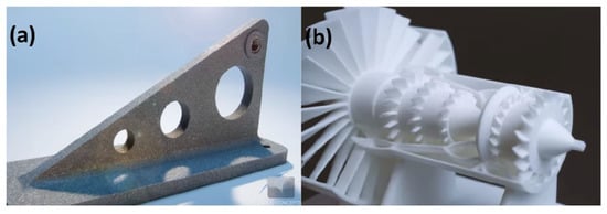
Figure 2.
SLS manufactured (
a
) fixture and (
b
) single part turbine.
3. Selective Laser Melting (SLM)/Direct Metal Laser Sintering (DMLS) as Currently Used for Metals
Selective laser melting (SLM) is a powder bed process that uses a high-intensity laser to melt the powder in a layer. The structure is generated from a CAD file that is sliced into thin cross-sections or layers. These data are converted to an STL file readable by the printing machine that supports any complex design. The build process begins with a thin layer of metal powder spread on the substrate plate in a build chamber. The high-energy laser scans the cross-section to fuse the powder into the regions described in the STL file. When the scanning is complete, the build platform lowers and another layer of powder is spread over the substrate and the process is repeated until all the layers are scanned and built one on another to create the 3D physical model. During the process, high temperature is required for melting, the production chambers maintain an inert or vacuum atmosphere to control the oxygen content to avoid oxidation and other problems affecting the properties of the produced turbine blade. Laser power, hatch distance, layer thickness, scan strategy, and scan speed are the parameters primarily used to optimize the process. When heating and fusing occur, the heating capacity depends on the mass and materials. When the energy is insufficient due to the mixing of low laser power, large layer thickness, and high scanning speed, it generates a balling phenomenon due to insufficient surface wetting. This deteriorates the quality of the product. Additionally, increasing the hatching distances results in regular porosity because the powder does not fuse well together. To achieve complete densification of the part, optimized minimum energy is required. A certain degree of overlap also ensures sufficient densification. SLM operating parameters are modified to improve surface quality. Figure 3 shows the steps involved in the SLM process to build the products. The final parts require post-processing techniques such as sand blasting, machining, and electro-machining. The tensile properties of SLM parts can be superior compared to traditionally manufactured parts. Compared to casting, SLM reduces building time, which is of high value in aero-structures [83][7]. Not only printing the products, SLM also offers the ability to assist in the repair and maintenance of the worn and burn-out parts faster and easier than the traditional repair methods. An example of this is the repair of the worn-out burner tip exposed to hot gas in the combustion chamber developed by Siemens in 2013. Siemens has developed a customized SLM machine that can repair the parts quickly and also economically. Such a method of SLM-based repair leads to a much smaller area of the burner tip being removed and replaced. As a result, the repair time is reduced to 90% of the usual time.
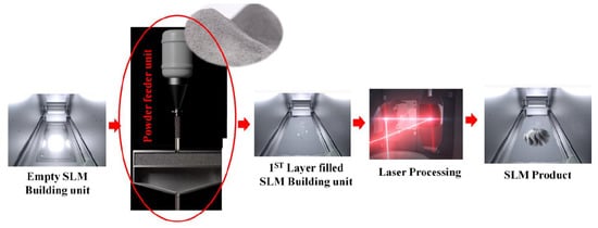
Figure 3.
SLM process sequence in the building unit.
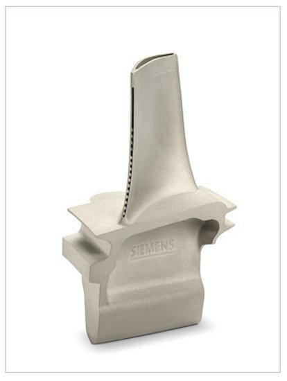
Recently, Siemens designed newer turbine blades to be manufactured using DMLS technology [3,84][1][8]. In collaboration with Material Solutions, the turbine blades were successfully 3D printed on an Eosint DMLS machine using a nickel super-alloy powder. The 3D printed blades were tested on a 13-megawatt SGT-400-type industrial gas turbine under full-load conditions. The blades were found to withstand extreme pressures and temperatures of about 1250 °C at 13,000 rpm. With the adoption of AM, the design and development of the blade went from component design to testing in just 18 months, which otherwise would have consumed six months. These blades had improved internal cooling geometry, which was possible because of the design flexibility of AM. The 3D printed turbine blade made up of a Ni-based super alloy developed by Siemens is shown in Figure 4.
4. Electron Beam Melting
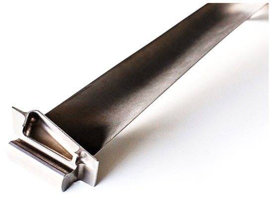
Electron beam melting (EBM) is an additive manufacturing process that uses an electron beam to melt and fuse the metal powders spread on the platform in a controlled atmosphere. The energy density in the electron beams is controlled by electromagnetic coils to increase the melting capacity, thus leading to an increase in productivity compared to SLM machines. Absorption of the electron into the material generates a negative charge, which can generate a repulsive force around the powder particles that can throw the finer particles from the powder bed, creating a powder cloud. In addition, the increased negative charge can also reflect the incoming electrons, creating more beams for diffusion. Consequently, the powder bed must be conductive to be processed with this method. Adjacent scanning strategies must also reduce the formation of these negatively charged particles in a particular location. As a result, the size of the melt pool increases, which decreases the resolution of the parts produced. In the aerospace industries, EBM is used to produce the quasi-shaped component and electric discharge machining (EDM) is applied to obtain the final shape [86][10]. EBM is associated with a greater thickness for each layer of powder; while increasing production rate creates an inferior surface finish, the powder remains in the 45 µm to 150 µm ranges. However, using smaller particles can produce a higher surface finish while productivity suffers. Therefore, the EBM process results in lower resolution and higher surface roughness than SLM. The remaining loose powder can be recycled in EBM, which contributes to effective use of the material. One of the advantages of EBM over SLM is that EBM parts are always produced in a vacuum chamber, resulting in less absorption of impurities throughout the entire process. Fewer impurity uptake facilitates the production of highly reactive materials. Residual thermal stresses are a major concern due to the increase in the cooling rate and the temperature gradient. This involves heating the powder bed to reduce the temperature gradient. In the case of EBM, minimal residual stress is observed compared to the SLM manufactured parts. However, preheating the powder bed can increase powder size by sintering. In this case, the size of the powder is reduced by prior grinding, which is a part of EBM processing, to maintain the optimum particle size [87][11]. Figure 5 shows a turbine blade fabricated using the EBM technique.
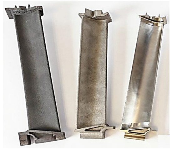
Recently, Avio Aero, a General Electric (GE) Aviation company, has installed 35 ARCAM EBM machines in the USA and Europe, which will be primarily focused on printing TiAl turbine blades on the LPT of the latest massive GE9X engine [9][13]. The GE9X engine was developed for Boeing’s 777X Jet engine, the world’s largest jet engine. These Arcam EBM machines use a powerful 3-kilowatt electron beam to melt the final grains of TiAl powders to build 40 cm long blades. The TiAl is a high melting point alloy and is also a strong material. GE has observed that the additively manufactured TiAl blades weighed 50% less compared to the traditional Ni-based alloy blades. Such weight reductions are expected to reduce the fuel consumption by 10% as well as the emissions compared to its GE90 engine. Such contributions are significant achievements in the aerospace industry. At their facility, GE can print six TiAl blades per batch using Arcam EBM machines. The additively manufactured TiAl blades spin at 2500 rpm inside the engine and withstand searing heat with a huge amount of force. The 3D printed GE that made TiAl LPT blades is shown in Figure 6.
5. Binder Jetting Process
The binder jetting process is another family of additive manufacturing processes in which the selected binder is deposited onto the powder bed selectively. The binder creates bonds between the particles to form a solid part in a layer. Using this process, granules of metals, sand, and ceramics are processed to form solid parts [90,91,92][15][16][17]. Since the raw materials are not processed directly to form the solid product, but rather the binder only binds the powder particles, leading to low sinterability of the particles. Hence, the density of the products is not up to the mark, especially in the case of ceramic powder based products, and thus the properties of the products are not adequate. Several attempts have been made to improve the density of the product, which depends on the powder particle size that relates to the flowability, choice of binder, building parameters, equipment specifications and parameters, and design of the product to be built, etc. [93][18]. Recently, Air Force Research Laboratory (AFRL) in the USA has collaborated with Exone, a binder jetting 3D printer manufacturer. The contract was given to qualify AF-9628, a high-strength steel produced by the U.S. Air Force, for binder jetting. Although AF-9628 parts were produced by other additive manufacturing techniques such as PBF, the binder jet process was found to print the parts more economically. Interestingly, these binder jet printed parts were 20% stronger than those processed by other AM techniques [94][19].
6. Laser Cladding
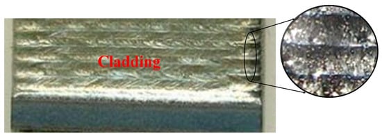
The principle of laser cladding is to use a metal filler in a very thin layer to fuse different layers and ensure a metallurgical bond between the different substrate surfaces. The laser beam can distribute a precise and localized heat input to the fillers. In industrial applications, laser cladding is used for rapid manufacturing, part repair, surface coating, and the development of innovative alloys. In particular, laser cladding is a flexible process that can fabricate functionally graded materials and heterogeneous components due to its ability to mix more than one type of powder by controlling the feed rate of each process. In addition, the technology enables the design at a microstructural level by varying the gradient of the material with localized fusion and the strong mixing motion present in the melt pool. Thus, the materials can be structured for flexible functional performance in their respective applications. The complex thermal history associated with the rapid heating and cooling rates of the technique allows for prolonged solid solubility in metastable phases or the production of non-equilibrium phases. CLAD requires accuracy as the part is produced by finer deposits, an optimized setting, and exact geometric control over the features of the deposits. The CLAD nozzle ensures that the input of metal powder melts them to generate the maximum yield of multidirectional deposits while ensuring optimal gas coverage [95][20]. Figure 7 shows the morphology of the laser coating of Stellite Grade 6 on carbon steel [96][21].
7. Laser Engineering Net Shape
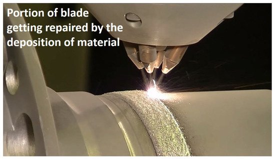
Laser powder forming, also known as proprietary (Laser Engineering Net Shaping, LENS), is a sub-category of direct energy deposition (DED) process, focused on manufacturing metal components directly from the CAD file using a metal powder injector directed to the molten pool. The molten pool is made using the laser heat source. The process can produce structures with near-net-shape parts with complex geometries where, conventionally, it is difficult to manufacture parts with exact specifications. The greatest advantage of LENS over SLS, SLM, and EBM is the size of the product that can be printed. The build volume in LENS can go up to several feet, while it is a maximum of 40 cm in the latter cases. A laser melts the injected metal powder at the focal point of its heating source with a deposition head. The laser beam usually travels through the center of the head. The laser is further focused using lenses [98][23]. The X–Y table moves with patterns defined to produce the different layers of the part. A new layer of powder is sprinkled on the last layer and the platform is lowered. Gravity or pressurized carrier gas are suitable means for dispensing and distributing metal powders around the circumference. Layer-to-layer adhesion improves from a higher wetting surface. Shielding gases protect the weld pool from oxidation and other atmospheric impurities during production. Selective laser sintering is similar to LENS in many ways and contrasts metallic powder as a powder applied directly to the deposition location at that moment. A wide range of alloys including titanium, stainless steel, aluminum, and other special materials can be made from composite materials and functionally graded materials [99][24]. In addition, Optomec’s laser cladding technology and LENS metal AM systems that are based on a directed energy deposition (DED) process are also used in turbine blade applications to repair turbine blade tips. Figure 8 shows the repair of a turbine blade using an Optomec made AM machine system [100][25].
8. Electron Beam Free-Form Fabrication
Electron beam free-form fabrication (EBF3) is another process of the DED family, a method that fabricates parts, which are close to near-net-shape (Figure 9). This saves raw materials, which offers a great advantage over traditional practices. On a metal substrate, a focused electron beam creates a molten pool in a vacuum environment that helps to generate a cross-section. The practice of electron beam welding for additive manufacturing was first founded by Vivek Davé in 1995 in his doctoral thesis at MIT. However, EBF3 was a name given by the NASA team that developed the process. Karen Taminger, materials research engineer for NASA’s LaRC, was primarily responsible for developing the use of electron beams in additive manufacturing to further improve the manufacturing process. Therefore, EBF3 is a NASA patented additive manufacturing technique used to fabricate near-net-shape parts with less material and workmanship. EBF3 is a method that can build metal parts in zero gravity environments. This additive process uses a solid feed stock that is melted using an electron beam to produce metal structures [102][27]. The advantages and capability of the process make it interesting to fabricate parts in space. Currently, the titanium spars for the vertical tails of the F-35 Joint Strike Fighter are manufactured using this manufacturing technique. Reduced titanium waste and shorter processing times have led to an increase in production rate and resource savings for the company, Lockheed Martin, and Ferra Engineering, based in Brisbane, Australia, intend to open the first factory in the world for the production of the F-35 components. EBF3’s ability to control the performance of its aircraft components by controlling material properties has drawn a lot of attention to this process. The EBF3 method is scalable for various applications as it can accommodate sizes ranging from inches to a few feet depending on the size of the chamber [103][28].
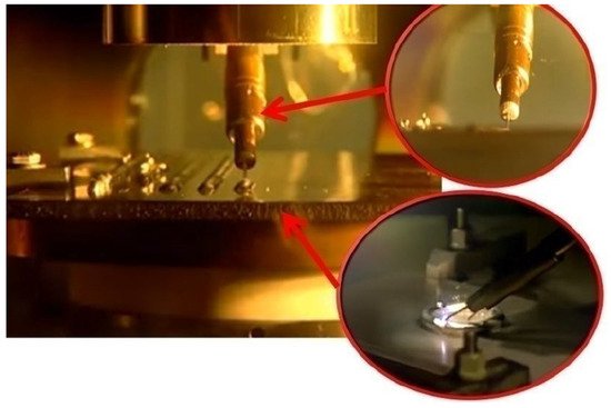
Figure 9. Electron beam freeform fabrication technique showing the first layer building in the layer-by-layer process [104].
Electron beam freeform fabrication technique showing the first layer building in the layer-by-layer process [29].
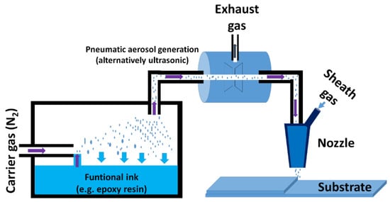
9. Aerosol Jet Process
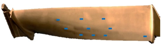
The aerosol jet process is a patented technique of electronic and metal 3D printer manufacturer, Optomec, which is based in New Mexico. It is a trademark of Optomec, which is a company that has been developing AM solutions since 1997. The company offers an exciting area of 3D printing that includes the printing of sensors. Such sensors that are part of advanced control and monitoring systems can be printed on the turbine blades. This increases the efficiency of monitoring the turbine blades during operation. Figure 10 shows the 3D printed turbine blade that is integrated with creep sensors to monitor the structural health of turbine blades [105][30]. Such advanced design features can be brought into reality only by additive manufacturing.
Optomec Company offers an exciting area of 3D printing that includes the printing of sensors. Such sensors that are part of advanced control and monitoring systems can be printed on the turbine blades. This increases the efficiency of monitoring the turbine blades during operation. Figure 11 shows the 3D printed turbine blade that is integrated with creep sensors for monitoring the structural health of turbine blades [105][30]. Such advanced design features can be brought into reality only by additive manufacturing.
References
- EOS Turbine Blade. Available online: https://www.eos.info/en/3d-printing-examples-applications/production-and-industry/turbomachinery-turbines (accessed on 15 November 2021).
- Jiang, R.; Kleer, R.; Piller, F.T. Predicting the Future of Additive Manufacturing: A Delphi Study on Economic and Societal Implications of 3D Printing for 2030. Technol. Forecast. Soc. Chang. 2017, 117, 84–97.
- Richardson, J.J.; Cui, J.; Björnmalm, M.; Braunger, J.A.; Ejima, H.; Caruso, F. Innovation in Layer-by-Layer Assembly. Chem. Rev. 2016, 116, 14828–14867.
- Turbine Blade 1c. Available online: https://www.wikiwand.com/en/Turbine_blade (accessed on 15 November 2021).
- Magerramova, L.; Vasilyev, B.; Kinzburskiy, V. Novel Designs of Turbine Blades for Additive Manufacturing. In Proceedings of the ASME Turbo Expo 2016: Turbomachinery Technical Conference and Exposition, Seoul, Korea, 13–17 June 2016.
- Kruth, J.P.; Wang, X.; Laoui, T.; Froyen, L. Lasers and Materials in Selective Laser Sintering. Assem. Autom. 2003, 23, 357–371.
- Yap, C.Y.; Chua, C.K.; Dong, Z.L.; Liu, Z.H.; Zhang, D.Q.; Loh, L.E.; Sing, S.L. Review of Selective Laser Melting: Materials and Applications. Appl. Phys. Rev. 2015, 2, 041101.
- Additive Manufacturing: Siemens Uses Innovative Technology to Produce Gas Turbines. Available online: https://press.siemens.com/global/en/feature/additive-manufacturing-siemens-uses-innovative-technology-produce-gas-turbines (accessed on 15 November 2021).
- Simens Ni Alloy Based Turbine Blade. Available online: https://blogs.sw.siemens.com/nx-design/3d-printing-in-nx/ (accessed on 15 November 2021).
- Galati, M.; Iuliano, L. A Literature Review of Powder-Based Electron Beam Melting Focusing on Numerical Simulations. Addit. Manuf. 2018, 19, 1–20.
- Rafi, H.K.; Karthik, N.V.; Gong, H.; Starr, T.L.; Stucker, B.E. Microstructures and Mechanical Properties of Ti6Al4V Parts Fabricated by Selective Laser Melting and Electron Beam Melting. J. Mater. Eng. Perform. 2013, 22, 3872–3883.
- EBM Made Turbine Blade by GE. Available online: https://www.ge.com/additive/stories/additive-at-scale-avio-aero (accessed on 15 November 2021).
- GE Aviation Invests in Widespread Rollout of GE Additive Arcam EBM Technology to Support GE9X Blade Production. Available online: https://www.ge.com/additive/press-releases/ge-aviation-invests-widespread-rollout-ge-additive-arcam-ebm-technology-support-ge9x (accessed on 15 November 2021).
- Kellner, T. Avio Aero, a General Electric (GE) Aviation EBM Turbine Blade. Available online: https://www.ge.com/news/reports/future-manufacturing-take-look-inside-factory-3d-printing-jet-engine-parts (accessed on 15 November 2021).
- Yadav, P.; Fu, Z.; Knorr, M.; Travitzky, N. Binder Jetting 3D Printing of Titanium Aluminides Based Materials: A Feasibility Study. Adv. Eng. Mater. 2020, 22, 2000408.
- Mostafaei, A.; Stevens, E.L.; Hughes, E.T.; Biery, S.D.; Hilla, C.; Chmielus, M. Powder Bed Binder Jet Printed Alloy 625: Densification, Microstructure and Mechanical Properties. Mater. Des. 2016, 108, 126–135.
- Popov, V.V.; Grilli, M.L.; Koptyug, A.; Jaworska, L.; Katz-Demyanetz, A.; Klobčar, D.; Balos, S.; Postolnyi, B.O.; Goel, S. Powder Bed Fusion Additive Manufacturing Using Critical Raw Materials: A Review. Materials 2021, 14, 909.
- Varotsis, A.B. Introduction to Binder Jetting 3D Printing- 3D HUBS. Available online: https://www.hubs.com/knowledge-base/introduction-binder-jetting-3d-printing/ (accessed on 15 November 2021).
- Everett, H. Exone to Develop High-Strength Steel Alloy for U.S. Air Force—3d Printing Industry. Available online: https://3dprintingindustry.com/news/exone-to-develop-high-strength-steel-alloy-for-u-s-air-force-177992/ (accessed on 15 November 2021).
- Fang, X.; Du, J.; Wei, Z.; He, P.; Bai, H.; Wang, X.; Lu, B. An Investigation on Effects of Process Parameters in Fused-Coating Based Metal Additive Manufacturing. J. Manuf. Process. 2017, 28, 383–389.
- Eboo, G.M.; Blake, A.G. Laser Cladding of Gas Turbine Components. In Proceedings of the ASME 1986 International Gas Turbine Conference and Exhibit, Dusseldorf, Germany, 8–12 June 1986.
- Alimardani, M.; Fallah, V.; Khajepour, A.; Toyserkani, E. The Effect of Localized Dynamic Surface Preheating in Laser Cladding of Stellite 1. Surf. Coatings Technol. 2010, 204, 3911–3919.
- Izadi, M.; Farzaneh, A.; Mohammed, M.; Gibson, I.; Rolfe, B. A Review of Laser Engineered Net Shaping (LENS) Build and Process Parameters of Metallic Parts. Rapid Prototyp. J. 2020, 26, 1059–1078.
- Vaezi, M.; Chianrabutra, S.; Mellor, B.; Yang, S. Multiple Material Additive Manufacturing—Part 1: A Review. Virtual Phys. Prototyp. 2013, 8, 19–50.
- Albuquerque Optomec Customers Surpass 10 Million Turbine Blade Repairs. Available online: https://optomec.com/optomec-customers-surpass-10-million-turbine-blade-repairs/ (accessed on 15 November 2021).
- Carlota, V. Optomec Customers Have Repaired More than 10 Million Turbine Blades- Optomec. Available online: https://www.3dnatives.com/en/optomec-customer-surpass-10-million-turbine-blade-repairs-260820204/#! (accessed on 15 November 2021).
- Majumdar, T.; Eisenstein, N.; Frith, J.E.; Cox, S.C.; Birbilis, N. Additive Manufacturing of Titanium Alloys for Orthopedic Applications: A Materials Science Viewpoint. Adv. Eng. Mater. 2018, 20, 1800172.
- William, J.; Seufzer Robert, A. Hafley Height Control and Deposition Measurement for the Electron Beam Free Form Fabrication (EBF3) Process. Patent 9764415, 19 September 2017.
- Electron-Beam Freeform Fabrication (EBF3): Technology and Application. Available online: https://3d-expo.ru/en/article/proizvodstvo-elektronno-luchevoy-plavkoy-ebf-tehnologiya-i-primenenie-80098 (accessed on 15 November 2021).
- AMFG Application Spotlight: 3D Printing for Turbine Parts. Available online: https://amfg.ai/2020/02/06/application-spotlight-3d-printing-for-turbine-parts/ (accessed on 15 November 2021).
- Reitberger, T.; Hoerber, J.; Schramm, R.; Sennefelder, S.; Franke, J. Aerosol Jet® Printing of Optical Waveguides. In Proceedings of the 2015 38th International Spring Seminar on Electronics Technology (ISSE), Eger, Hungary, 6–10 May 2015.
More