Computer-vision-based target tracking can be applied to structural vibration monitoring, but current target tracking methods suffer from noise in digital image processing. AIn this paper, a new target-tracking method based on the sparse optical flow technique is introduced to improve the accuracy in tracking the target, especially when the target has a large displacement. The proposed method utilizes the ORB technique to maintain a variety of keypoints and combines the multi-level strategy with a sparse optical flow algorithm to search the keypoints with a large motion vector for tracking. Then, an outlier removal method based on Hamming distance and interquartile range (IQR) score is introduced to minimize the error. The proposed target tracking method is verified through a lab experiment---a three-story shear building structure subjected to various harmonic excitations. It is compared with existing sparse optical flow-based target tracking methods and target tracking methods based on three other types of techniques, i.e., feature matching, dense optical flow, and template matching. The results show that the performance of target tracking is greatly improved through the use of a multi-level strategy and the proposed outlier removal method. The proposed sparse optical flow-based target tracking method achieves the best accuracy compared to other existing target tracking methods.
1. Proposed Target Tracking Method
Computer vision techniques have led to great advancements in detecting and tracking objects and are being increasingly researched for applications in vibration monitoring of structural systems to replace conventional contact-based discrete sensors. In computer-vision-based vibration monitoring methods, the displacement time history of a specific target on the structure is measured by the tracking changes in the video frames, and then the displacement response is converted to acceleration response using numerical differentiation methods. Compared with conventional measurement, visual-sensing-based methods do not require the installation and maintenance of expensive sensor setups.
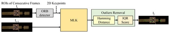
In ththis study, a novel sparse-optis entry, a novel sparse-optical-flow-based target tracking approach for structural vibration monitoring is proposed. As shown in Figure 1, the conventional sparse optical flow algorithm (i.e., LK) is enhanced to track a set of sparse keypoints accurately. A multi-level strategy is applied to the LK algorithm to enhance the large motion vector calculation. Moreover, Oriented Fast and Rotated Brief (ORB), a corner extraction algorithm, is used to detect the keypoints, and an outlier removal method based on Hamming distance and interquartile range (IQR) score is introduced to minimize the error between the experimental response versus the vision-based response.
Figure 1. Flowchart of the proposed sparse-optical-flow-based target tracking method. ORB: Oriented Fast and Rotated Brief, MLK: multi-level Lucas–Kanade algorithm, IQR: interquartile range.
2. Vision-Based Sensing System
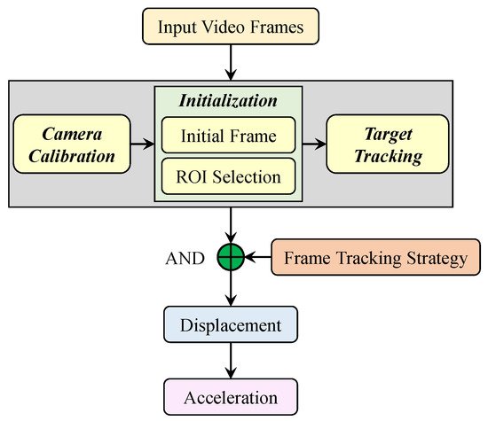
The visual sensing system used for structural vibration monitoring is based on target tracking techniques. As shown in
Figure 2, this system takes the video frames that record the vibration of a structure as an input and outputs the acceleration time histories of the structural vibration. It consists of two components: (i) camera calibration and scale conversion; and (ii) frame tracking strategies and displacement calculation.
Target tracking is used to calculate the motion of the vibrating structure between two continuous frames, i.e., the previous frame and the current frame. Then, the calculated motion is combined with the frame tracking strategy to obtain the displacement time history of the structural vibration. T
heo displacement time history is often calculated by either employing a fixed-frame strategy or an updated-frame strategy. The main difference between these two strategies is whether the reference frame is kept save on computational resources, an ROI is defi
xned
or is updated when calculating the displacement for each tracked target. In this study, we employ the updated frame tracking strategy to get the displacementin the first frame.
To save on computational resources, an ROI is defined in the first frame.
Figure 2.
Flowchart of the visual sensing system.
3. Experiments Setup
The accuracy of the proposed method is evaluated by measuring the acceleration response from a three-story shear building in the laboratory subjected to three different harmonic transient excitations. The oververview of the experimental setup is shown in Figure 3. A three-story shear building structure (see Figure 4) is fixed on the shake table and subjected to harmonic loads excitation using an excitation system. A reference system measures the acceleration time series response for the vibration of each floor under different excitation frequencies. A vision sensor system records the structural vibration for acceleration calculation,.
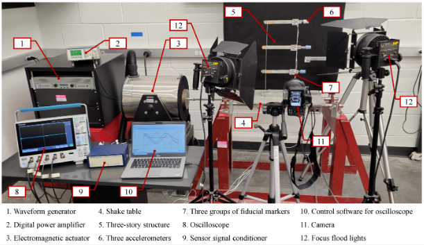
Figure 3. whOvere a Nikon Z 7 Mirrorless Digital Camera equipped with a Nikon NIKKOR Z 24–70 mm f/4 S Lens is positioned at a distance of 900 mm away from the frame to record the structural vibration in the videoview of the experimental setup.
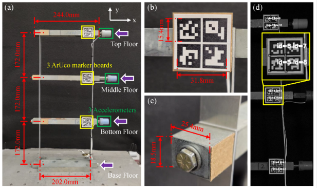
Figure 3. Overview of the experimental setup.
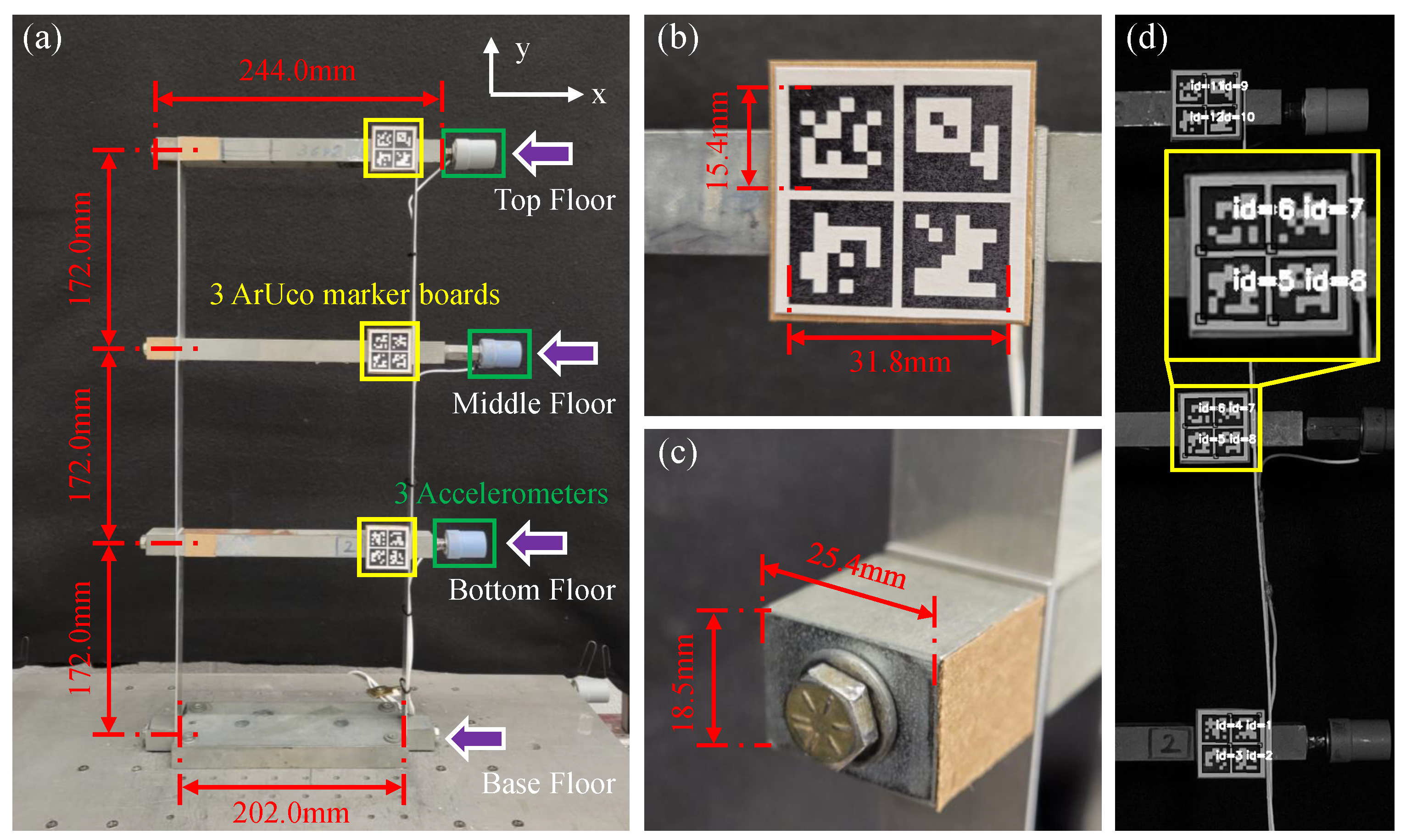
Figure 4. Experimental three-story shear building structure. (
a) Overview of the structure; (
b) close-up shot of the ArUco marker board fixed on the top floor; (
c) left end of the lumped mass steel stick of the middle floor; (
d) detected ids of the fiducial markers.
4. Qualitative and Quantitative Assessment of the Proposed Method
The proposed vision-based target tracking method for structural vibration monitoring is evaluated qualitatively and quantitatively through the laboratory-scale experiment. It is implemented by carrying out three key steps: (i) sparse optical flow calculation, (ii) Hamming distance-based outlier removal method, and (iii) IQR score-based outlier removal method. The proposed vision-based target tracking method for structural vibration monitoring is evaluated qualitatively and quantitatively through the laboratory-scale experiment.
The proposed target tracking method is implemented by carrying out three key steps: (i) sparse optical flow calculation, (ii) Hamming distance-based outlier removal method, and (iii) IQR score-based outlier removal method. Figure 5 shows two instances of the frame (It, It+1) to compare the effects of three steps qualitatively. The colored circles in Figure 5 represent the keypoints 2D position: (xi, yi) detected by the ORB detector in frame It and the optical flow algorithm in frame It+1, and each of them is a local extremum whose pixel intensity is greater or smaller than all its neighbors. Images in Figure 5a show the pairs of matched keypoints in the ROIs of the previous frame, It, and the current frame, It+1, after implementing all three steps. The colored lines connect the matched keypoints in the ROI of It and their corresponding keypoints in It+1. Images in Figure 5b show the motion trajectories (green lines) for the matched keypoints (green dots) in the ROI of b show the motion trajectories (green lines) for the matched keypoints (greens dots) in the ROI of It from time t to t+1. The matched keypoints shown in Figure 5(a-iii) are much more distinct and have greater clarity compared to the keypoints observed in Figure 5(a-i). As seen in Figure 6, the response obtained from the proposed method matches closely with the measured response., the response obtained from the proposed method matches closely with the measured response.
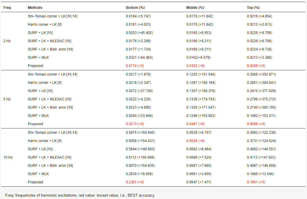
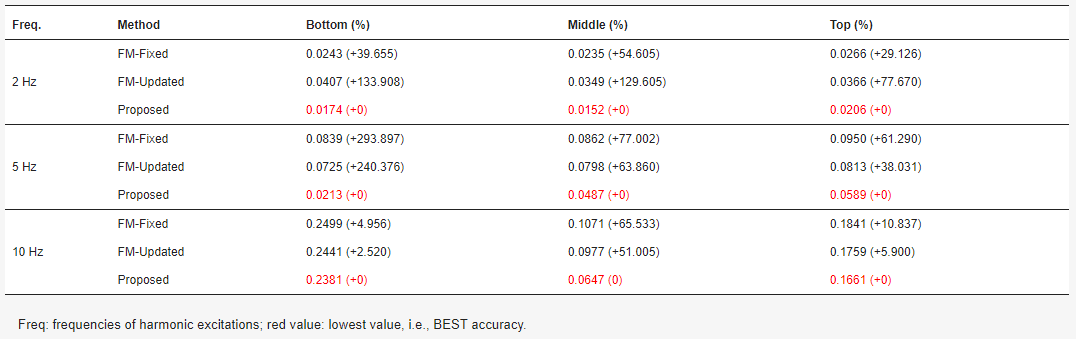
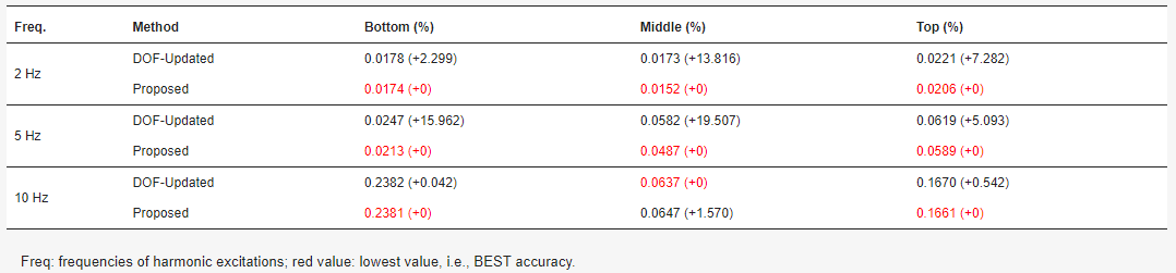
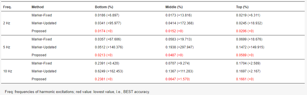
The proposed method is also compared with existing sparse-optical-flow-based target tracking methods (see Table 1) and target tracking methods based on three other types of techniques, i.e., feature matching (see Table 2), dense optical flow (see Table 3), and template matching (see Table 4). The results show that the performance of target tracking is greatly improved through the use of a multi-level strategy and the proposed outlier removal method. The proposed sparse-optical-flow-based target tracking method achieves the best accuracy compared to other existing target tracking methods.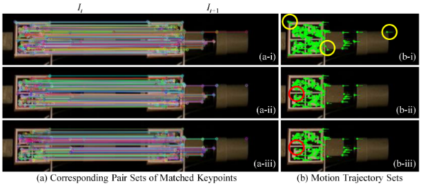
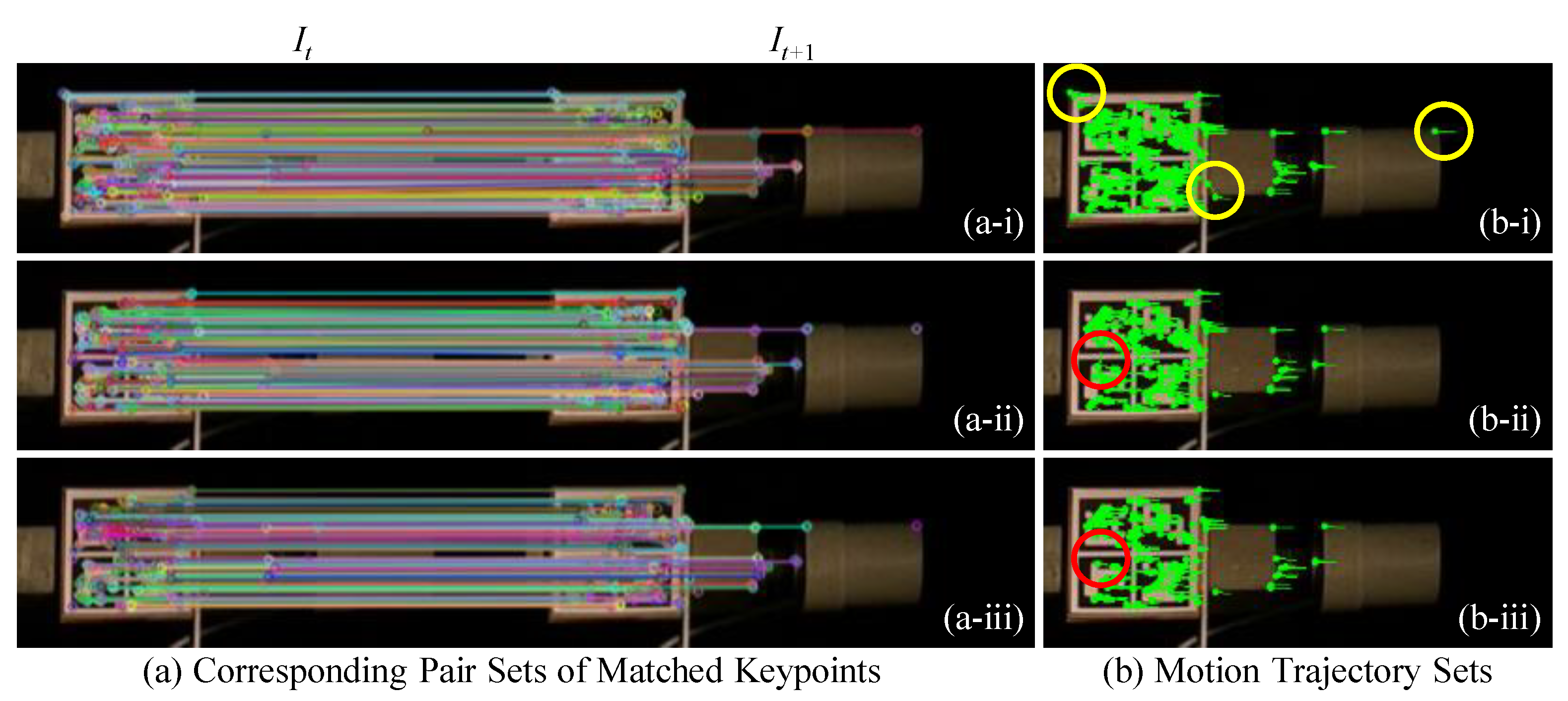
Figure 5. Qualitative example of the sparse-optical-flow-based target tracking. Pairs of matched keypoints in the ROIs of the previous frame, It, and the current frame, It+1, after implementing (a-i) sparse optical flow calculation, (a-ii) Hamming distance-based outlier removal method, and (a-iii) IQR score-based outlier removal method. Motion trajectories for the matched keypoints in the ROI of It from time t to t+1, after implementing (b-i) sparse optical flow calculation, (b-ii) Hamming distance-based outlier removal method, and (b-iii) IQR score-based outlier removal method.
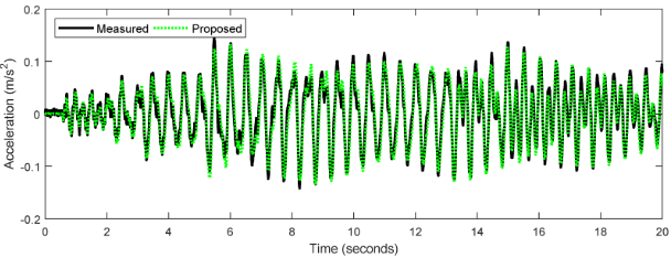
Figure 6.
Comparison of middle floor acceleration response from the accelerometer and the proposed method at 2 Hz.
Table 1. RMSE (mm) and its error percentages (%) for sparse optical flow tracking methods.
Table 2. RMSE (mm) and its error percentages (%) for feature-matching-based tracking methods.
Table 3. RMSE (mm) and error percentages (%) for dense optical flow tracking methods.
Table 4. RMSE (mm) and error percentages (%) of existing template-matching-based target tracking methods.
The proposed method is compared with existing sparse-optical-flow-based target tracking methods and target tracking methods based on three other types of techniques, i.e., feature matching, dense optical flow, and template matching. The results show that the performance of target tracking is greatly improved through the use of a multi-level strategy and the proposed outlier removal method. The proposed sparse-optical-flow-based target tracking method achieves the best accuracy compared to other existing target tracking methods.