1. Introduction
This
sent
udry’s main objective is to reduce carbon dioxide emissions from the atmosphere and meet the population’s energy demand without harming the climate. A gas turbine can operate at a higher temperature and achieve maximum work output, with minimum energy loss. The advanced gas turbine engine will work in modern times using renewable or non-renewable energy resources for industrial applications, such as producing electricity and operating for the aerospace engine. With the aid of thermal barrier coating in this field, the market area is expected to reach USD 30.7 billion by 2025. Various researchers have found that gas turbine engine modification improves the superior turbine blade efficiency
[1]. Technological improvement in gas turbines plays a vital role in filling rising energy requirements and reducing the carbon dioxide emission rate. The challenge facing gas turbines is to prevent their working parts from degradation, as the turbine works at a higher temperature and a corrosive environment
[2]. The steam turbine engine’s work quality depends on a higher gas inlet temperature and reduced energy loss during turbine blade operation. The combustion chamber’s temperature is maintained inside by using the turbine component’s insulation with the surface coating process’s help, preventing the turbine component from degradation. Sometimes, the working temperature of steam turbine blades is above the range of melting temperature of the base metal, and overcoming this problem is to use a suitable coating method. By efficiently supplying internal air cooling, the substrate material’s surface temperature can be reduced up to 300 °C
[3]. TBCs have been developed to insulate the substrate material’s surface layer and prevent thermal shocks and corrosive environmental conditions during work. The thermal spray process is widely used for coating the gas turbine component because it can coat intricate shapes. TBC can also affect several factors, such as heat flux, heat transfer coefficients, coating thickness, and thermal conductivity, to define the substrate’s magnitude of temperature decrease. These constant efforts to increase a gas turbine engine’s efficiency have resulted in working temperatures to over 1300 °C, which requires thicker TBCs with their chemistry development, including the newly cooling system
[4]. If the topcoat thickness increases, the substrate coating components’ surface temperature decreases from 4–9 °C per 25 μm and avoids surface coat failure under higher-temperature oxidation conditions
[5]. The thermal stability of the turbine components at higher temperature thermal shock resistance and wear resistance using conventional or nanostructured coating methods is also helpful for coating the complex shape components for gas turbines or diesel engines. Increased steam turbine engines’ efficiency eventually provides practical assistance in aircraft performance and fuel efficiency and supports them in carrying increased payloads. The gas turbine engine produces the maximum amount of mechanical work output for low wastage of thermal energy in land-based applications. It helps generate electricity in thermal power stations.
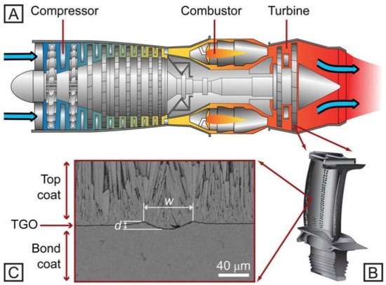
Figure 1 shows that the compressor sucked the air from the environment, then compressed that at a higher pressure; after this, it delivers this air into the combustion chamber, where it helps for burning the all-fuel particles that help for generating the higher amount of heat energy inside the combustion chamber and reduce the wastage of unburned fuel particles. The turbine inlet temperature is similar to the combustor outlet temperature and turbine blades are used to convert the heat into mechanical energy by revolving them into high speed
[6].
Figure 1.
(
A
) Schematic diagram of a gas turbine, (
B
) Blade of the turbine and (
C
) cross-section TBC system [6].
The thermal efficiency (η) of a gas turbine following an ideal Carnot cycle
[7]:
where, T
exit = represent the exit temperature of the gas, T
inlet = represent the inlet temperature of the gas.
Equation (1) shows that increasing the gas turbine’s inlet temperature can improve its thermal efficiency
[7]. Raising the turbine’s inlet temperature sets an immediate requirement on the materials working in the gas turbine’s hot regions, where the temperatures approximate the range of 1500 °C
[8]. Here, the temperature is higher than the melting point of the most reliable working materials in gas turbines now, such as nickel-based superalloys. When rising the temperature of hot gas inside the turbine inlet, it is more important to control the temperature and protect the turbine component from degradation. Hence, it is feasible to use outside insulation of the surface material and an internal cooling system for turbine components. This internal cooling system is used to restrict the volume of air and control the heating temperature without decreasing the gas turbine’s thermal efficiency. When a quantity of air higher than 8% is utilized for cooling purposes for the turbine, the main benefit of this cooling system is to regulate the working temperature and increase the mechanical and thermal efficiency of turbine blades
[8]. Coating quality advancements can improve work performance and reliability
[9]. The researchers’ foremost challenge issues in surface coating are how to improve the thermal stability of the ceramic powder material at a higher working temperature to provide a better insulation property for the substrate metal
[10]. The various approaches and synthesis mechanisms can be used for materials processing in other applications
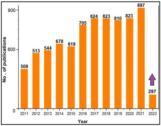
[11]. The details of papers published on thermal barrier coatings have been fetched from scopus.com (accessed on 23 August 2022) and presented in
Figure 2. Researchers are focusing on the challenges associated with thermal barrier coatings, and advancements are still going on in this field.
Figure 2.
Year-wise data published on thermal barrier coatings.
2. Thermal Barrier Coating System
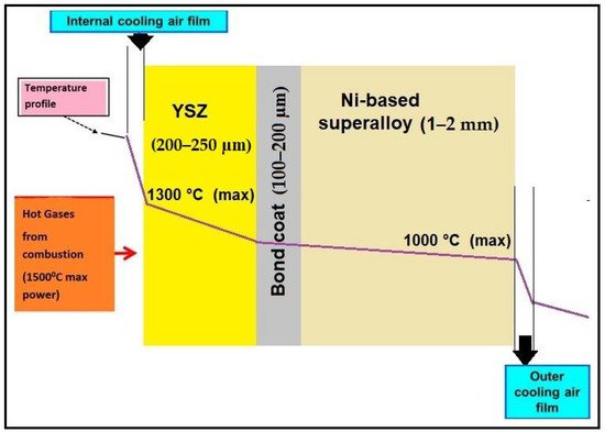
TBCs are coated processes used for intricate surface material systems that are useful for gas turbine engines implemented in hot regions. This multi-layered coated surface has a formation where the top coating layer comprises a lower thermal conductivity ceramic and thermal insulation from hot burning gases
[12]. The schematic is shown in
Figure 3. At maximum engine power, the modern turbine inlet temperature (TIT) of state-of-the-art jet plane turbines reaches a value of approximately 1500 °C. The component temperature level is higher than the maximum operating temperature of YSZ TBCs, which is around 1300 °C. Underneath the topcoat is a bond coat that contributes a vital role for bonding effect between the ceramic material and base metal for protecting turbine components against oxidation and corrosion effect at high temperatures and crossover working environment.
Figure 3.
Schematic of the Thermal Barrier coating (TBC) part in thermal gradient and air–cooling.
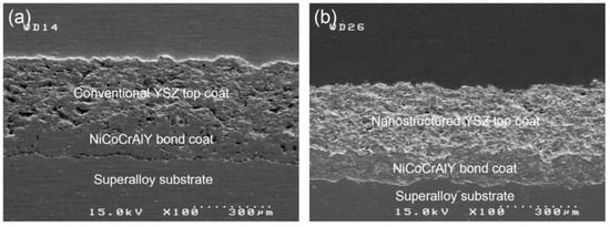
Figure 4 shows the SEM images of a polished cross-section of traditional as-sprayed and nanostructured TBCs, which constituted the YSZ topcoat and the NiCoCrAlY bond coat collected by the APS process on the superalloy substrate metal. After the solidification process was completed for the partially molten and completely molten powder grains, the conventional and nanostructured YSZ covered layered form. Micropores can be seen in the cross-section of the YSZ coating in both layers, as well as on the coating’s outer surface. Nevertheless, in the nanostructured coating produced from very fine grains, the inhomogeneities and micropores are frequently decreased, most likely due to the compactness of the nanostructure
[13].
Figure 4.
(
a
) FESEM polished cross-section micrographs of As-sprayed TBC with traditional or Conventional YSZ coating and (
b
) Nanostructure YSZ coating [13].
2.1. Material in a TBC System
2.1.1. TopCoat
The thermal spray coatings’ upper zone contributes heat resistance against the burning gases into a gas turbine engine’s combustion chamber. The durability and topcoat performance are increased by providing an internal cooling system that keeps the base metal’s heating temperature lower, which is why it does not decrease its load-bearing ability. This heating temperature can decrease from 150–250 °C in the upper layer topcoat, depending upon the coated layer’s thickness and the type of ceramic grain size
[13]. The ceramic powder materials have been investigated for insulation purposes for gas turbine blades by a thermal spray coating process used to improve the thermal stability of the topcoat materials. Yttria-stabilized zirconia (YSZ) powder was mainly used for industrial application because it provided better thermal stability. YSZ ceramic powder particles need to have many required characteristics for the working heat limit, such as increased melting point temperature, reduced thermal conductivity, and improved phase stability
[14].
The lower coefficient of thermal expansion is a significant factor in the improved life of coated surface material controlled by proper coating methods. A single ceramic material can be challenging to fulfil all of the coated ceramic materials’ conditions, using a mixture of two or more ceramic materials to overcome these situations. In addition to yttria-stabilized zirconia in the range of 6–8 wt.%, this gives the topcoat powder grains better performance because of its comparatively lower density, lower thermal conductivity and higher concentration for point defects
[15]. Many researchers want to develop the YSZ coating structure’s excellent quality, which improves the components’ durability and reliability at a higher working temperature
[16]. In the opposite direction, YSZ already has a few drawbacks for coating utilization, such as reduced working temperature less than 1200 °C, susceptibility to thermal corrosion, impressive atmospheric sediments, and stimulated thermally grown oxide generation large diffusivity of ionic oxygen in ceramics based on ZrO
2 [17].
Hence, it is essential to improve the coating material’s work performance and provide a more stable coating microstructure. To prevent the substrate metal from deteriorating at higher temperatures and corrosive environmental conditions. The 8YSZ/graphite powder material is used for high-temperature applications. It has good insulation properties that protect substrate metals by reducing the heat transfer rate between the coating and substrate surfaces
[18]. At present, various researchers have worked to produce agglomerated nanostructurednanostructured8 wt.% YSZ powder grains that can be used for the thermal spray coating process. The size range of conventional powder grains varies from 10 to 100 μm, but on the other hand, the size range of nanostructured powder grains varies from 40 to 50 nm. In the thermal spraying process YSZ, nano-clusters use feedstock to control the supply of powder grains during the working process. The nano-clusters agglomerate powder grains during spray drying, which can help obtain micro-sized particles for TBC coating
[19]. The coating quality relates to the complete molten for the powder grains before being deposited on the base material in the thermal spray process. The chemical reaction technique plays a significant role in manufacturing nanostructured powder grains and makes them capable of surface coating. The spray-drying method is an essential and valuable technique for agglomerating nanostructured powder grains. This technique helps protect them from overheating before depositing onto the substrate material
[20]. The various kinds of powder grains material utilized in combining multi-layered topcoat structured ceramics could be a successful option.
2.1.2. Bond Coat
Many scientists have improved the bond strength obtained from nanostructured powder grains. As a bond coat below a ceramic topcoat in TBC systems, MCrAlY has been commonly employed. By practising standard C633-01, the shift from the bond coat hardness is proposed to occur guided by this adhesive force when that breakdown occurs from the bond-coated base metal in this interface. That cohesive force fracture is entirely within this coated layer
[21]. Consequently, this bonding of the power inside the associated splitting is stronger than that without splitting. It is well understood that combining governs the adhesive strength of the situation within sprinkling materials, including the base material. The YSZ-based coating material manages residual tension from the base material’s coated form
[22]. This kind of residual stress is made from a couple of parts in that sprayed method, such as quenched stress that produces reduction for the various splats and cooled pressure generated by the unmatched heat extension between that deposited on the base material while all collectively cooled later deposited
[23]. One of the promising ultra-high-temperature applicant metals for a material bond coat is the intermetallic composite NiAl, which has a higher molten point (1638 °C), lower density (5.9 g/cm
3), relatively greater elastic modulus (240 GPa), and excellent oxidation protection at 1200 °C
[24]. On the other hand, the functional utilization of NiAl under a higher-temperature environment is restricted by its brittleness, low adhesion strength within this oxidation film, and base metal. This diffusion process occurs between the Ni and Al atoms because a higher temperature operation toward the model also limits the powder grain characterization of NiAl
[25,26][25][26]. After performing the experiments, it was observed that the more outstanding durability of bonding from the nanostructured coating was determined by the greater internal toughness achieved
[27,28][27][28]. As this conventional coated approach watched some inner face inside this powder material, some kept fully melted into the spray blast, and this base metal showed minor cracks. As this nanostructured coated, some interfaces inside this powder grain were partially melted during this spraying process. Adherents in the coating occurred in this base metal. Thus, interface cracks within the nanostructured-coated structure are prevented. The firm-adherent compact nanostructure increases the bond strength.
2.2. TBC Processing Methods
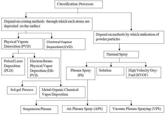
As shown in Figure 5, it offers a specific classification of processing techniques and the necessary process employed to deposition TBCs on the substrate metal, which has been mentioned in the following paragraphs. In the field of thermal spray, thermal plasmas are employed in atmospheric plasma spray (APS), suspension plasma spraying (SPS), solution precursor plasma spray (SPPS), Plasma Spraying –Physical Vapour Deposition (PS-PVD) vacuum plasma spray (VPS), low-pressure plasma spray (LPPS), and controlled atmospheric plasma spray (CAPS) methods.
Figure 5.
Wide classification of the coating process and methods used for material deposition.
The following sections extensively discuss atmospheric plasma spray (APS) because it is a standard coating method that can model typical thermal spray processes. Because of the relative amount of momentum supplied to the in-flight particles, plasma jet flow alters the trajectories of feedstock
[29,30,31][29][30][31].
2.2.1. Air Plasma Spray (APS)
This TBC material-deposited method typically defines this type of part coating to the spray jet, such as atmospheric plasma spraying (APS). In common, APS coated appear to have a horizontal splatted micro-structure with inter-splatted borders approximately equal for this top-coated and bond-coated interfacial
[32]. In this method, powdered material grains are injected in a thermal spray jet of higher heating range and melted within this jet of spray, which works for stimulation into the base metal where melted droplets spread that create splits efficiently quenched. The coated surface thickness can be increased by raising the number of successful splats deposited on the substrate metal. This coated structure quality mainly depends on the process parameters used for thermal sprays, such as the current, voltage, the flow rate of that gas, and the stand-off distance between the touch gun and substrate material during surface coating. The feedstock plays a vital role in supplying a sufficient amount of powder through the spray gun to obtain a successful coating structure. The feeder input parameters used to control this supply of powder grains include the temperature and size of the powder grains. The coated microstructure splats’ morphology depends on the angle of contact used to spray the powder grains to the substrate material
[33]. Some usually cracked cross-sections for this powder spraying coated surface by APS show films for the splatted simultaneously with inter-laminar holes and round holes
[34]. The coating’s porosity is structured depending upon the substrate’s surface temperature being reduced by increasing heat temperature and improving internal splat attachment, resulting in improved coating characteristics
[35].
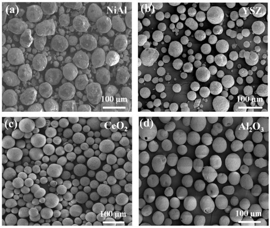
Figure 6 shows the powder’s morphology used for deposition in the substrate metal by the APS method in the existing work explained. The mean size was 40–70 μm for all globular agglomerated powder grains.
Figure 6.
FE-SEM images show the morphology of the (
a
) NiAl, (
b
) YSZ, (
c
) CeO
2
and (
d
) Al
2
O
3
feedstock powder.
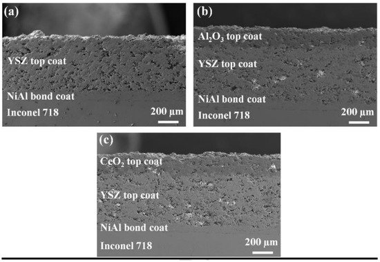
Figure 7 displays the FE-SEM images of the APS method-based individual-layered YSZ cross-sectional view, YSZ overlay of Al2O3, and YSZ coating overlay of CeO2. Besides, Al2O3 and CeO2 coatings are also considered crack-free and well adhered to the coating of the YSZ.
Figure 7.
Low magnification FE-SEM images show the plasma-sprayed cross-sectional surface (
a
) NiAl/YSZ, (
b
) NiAl/YSZ/Al
2
O
3
and (
c
) NiAl/YSZ/Al
2
O
3
/CeO
2
As shown in
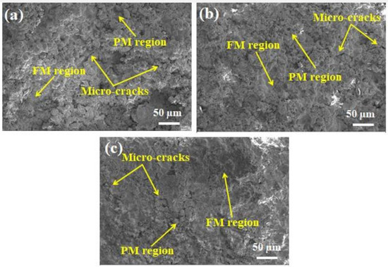
Figure 8, all three layers contained a bimodal microstructure consisting of an entirely melted section joined collectively to create a solid structure. The sponge-shaped microstructure portion is formed near the molten zone. APS coatings’ common characteristics, intermittently partially melted powder grains, micro-level cracks, and porosity play a significant role in the coated structure’s thermal oxidation and corrosion resistance behavior. As diffusion paths for molten salts, these partially melted power grains and micro-cracks work by enhancing the corrosion reaction between the dissolved salts and the ceramic powder
[36].
Figure 8. FE-SEM micrograph images of (
a) NiAl/YSZ, (
b) NiAl/YSZ/Al
2O
3 and (
c) NiAl/YSZ/Al
2O
3/CeO
2, based coating structure exhibiting the micro-cracks, partially melted (PM), fully melted (FM) region
[36].
Thermally grown oxide (TGO) mainly occurs between the top and bond coating structures because oxidation occurs during work at higher temperatures. The oxide layer growth mainly produced the maximum amount of stress inside the coating structure interface, which reduced the components’ service life. Experimental findings revealed that YSZ coating with Al
2O
3 as an overlay improved traditional YSZ’s hot corrosion protection by partly alleviating melted salt infiltration. However, by completely clearing the molten salt’s penetration in the YSZ, the YSZ layer with CeO
2as the overlay film showed more effective corrosion protection than traditional TBCs
[36]. Young’s modulus is the most significant factor in TBCs that influences the thermal stress distribution in the coating structure’s upper surface and improves the components’ work performance. Because of the porous microstructure, the upper surface’s macro-elastic properties are usually significantly less than this value for dense YSZ
[37] (see
Table 1). The relationship between the various parameters is shown in
Figure 9. The failure of the bonded structure in cracks appears near the splats region because of expanding numbers of thermal cycles during the experiment work and increasing the strain value, which affects the reduced macro-elastic strength
[38]. To determine the modulus of elasticity for the coated structure with depth-sensitive indentation, the methods were used, and stability depended upon the load applied for nanoindentation. With the heat treatment method’s help, the modulus of elasticity can be improved by heating the coated surface at 1100 °C
[39].
Figure 9.
The plasma spraying parametersfor the top coat’s second stage.
Table 1.
The plasma spraying parametersfor the top coat’s first stage.
| Substrate Material |
Powder Feed Rate (g/min) |
Current (A) |
Voltage (V) |
Power (kW) |
Stand-Off Distance (mm) |
| stainless steel [34] |
20–40 |
600 |
66–68 |
- |
100 |
| IN-738LC [35] |
25 |
600 |
60 |
36 |
150 |
| IN-738LC [40] |
38 |
600 |
- |
64 |
100 |
| Amdry 995C [37] |
60 |
600 |
65 |
- |
120 |
| 204B-NS [37] |
40 |
600 |
65 |
- |
130 |
| stainless steel [38] |
30 |
600 |
63 |
50 |
100 |
| stainless steel [38] |
35 |
600 |
67 |
42 |
120 |
| Inconel 718 [39] |
35–40 |
600 |
60 |
35 |
130 |
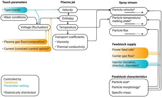
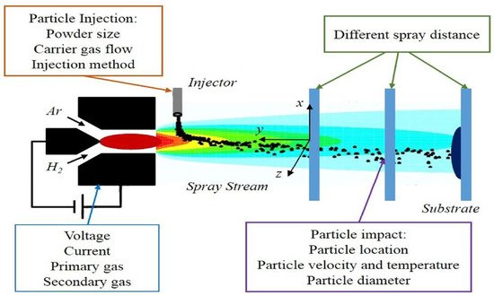
As shown in Figure 10, the H2 or Ar can be used as carrier gases in APS coating. These gases entered from the electrode hole that heated up and disintegrated them through the arc to form plasma. The nozzle can control the jet of plasma in this process by regulating the speed and flow rate of the burning gases. These burning gases are mainly used as carrier gases in this method. They mix into agglomerated nano- or micro-sized diameter powder grains that help melt them before being deposited on the substrate material. Many process parameters have been used in the APS method. However, some of the most significant parameters must be affected by the surface’s standardized coated properties and improve the microstructure quality.
Figure 10.
Themost important controller parameters used in APS [41].
Some necessary input parameters that must be controlled for better microstructure from the coated surface, such as the pressure of gas arc feed rate of powder grains, diameters of powder particles, the flow rate of carrier gas, angle of injection, the distance of spray, smoothness of the coated surface and base metal or metal substrate surface temperature before coating start
[41] (see
Table 1). Several research types have confirmed that the optimum parameters in this process play a significant role in APS. It controls phase structure and thermal durability, improves microstructure, enhances corrosion protection, and improves physical properties, such as the coating’s hardness and toughness.
2.2.2. Functionally Graded Coatings
Traditional coated methods have faced significant problems under working conditions. This coated structure usually fails earlier when presented under the thermal shock and erosion test due to this causing the spallation effect produced in a material that can start deteriorated coated structured from the interface between top and bond coat. In functionally graded (FG)coatings, multiple phases are produced and given a regular face structure. The ceramic topcoat faces a higher operating temperature under this coating system and sustains this heat under the combustion chamber, while this also functions as heat insulation
[42]. The coating must be done by depositing gradient material at a controlled amount to substrate metal during the process. The gradient material allows for the proper distribution of the stress generated around the coated surface and causes a decrease in strength. The bond coat strength has improved by reducing the thermal expansion gap between the top coated film and base metal after coating. When the higher amount of coated material is deposited through the spray drawing process and the diameter of traditional powder in microns used for coating, then the maximum chances for the spallation at the coating layer’s outer surface are then given. Some authors have produced nanostructured powder grains that troubleshoot this material spallation difficulty using nanostructured powder structured in YSZ TBCs material with a higher thermal expansion coefficient and lesser thermal conductivity overall
[43]. Different studies have focused on the effectiveness of various kinds of functionally graded coatings in decreasing heat stress and improving the coated structure’s mechanical properties, such as thermal shock resistance and excellent hardness value
[44]. Some researchers deposit the Al
2O
3/YSZ ceramic powder onto substrate materials and analyze its mechanical and thermal properties. The oxygen entrance is restricted by applying a thin surface coating of Al
2O
3 ceramic material and providing substrate metal thermal insulation. Spallation has formed inside the Al
2O
3 ceramic thick-coated structure while working at a higher temperature than can change the ceramic material phase from γ-Al
2O
3 to α-Al
2O
3. The coating material’s premature failure occurs when extra residual stress is generated inside the coating structure due to thermal oxidation
[45]. This
sent
udry will design a zirconium base coating material and examine fracture toughness using a theoretical modeling technique. This coating was done through the functionally graded process. A unique parameter is similar to the stress-intensity factor introduced to determine the toughening effect transform toughness equal to stress. The design methodology helps select optimal coating parameters that prevent the coated structure’s premature failure and improve the fracture toughness material
[46].
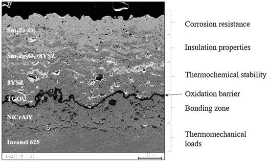
Figure 11 represents every layer’s purpose inside the functional zones of this functionally graded coating (FGC) technique. In hot corrosion conditions, the stimulation decomposed for the Sm
2Zr
2O
7 + 8YSZ way into the form of APS for the double ceramic layer (DCL) and functionally graded system (FGS) modes was examined. This investigation was to distinguish surface methods in a liquid sodium sulfate Na
2SO
4 environment that occur throughout the corrosion of FGC based on samarium zirconate and zirconium oxide with ratios 25/75, 50/50, and 75/25. After experimentation, the selective breakdown of samarium zirconate in the 50 8YSZ + 50 Sm
2Zr
2O
7 composition that system gave better corrosion resistance compared to others
[47].
Figure 11.
FE-SEM images show the functional zones of the FGC technique [47].
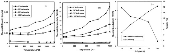
The functionally graded coating material with thermal diffusivity/conductivity progressively improved over the functionally graded zones compared to the variation in composition accompanying this coating mechanism; the testing specimens were compared. The thermal oxidation test was conducted at a temperature of 1300 °C for 1 h, and the cooling process was done at 25 °C for 20 min for holding time to completion of one cycle. The composite layers’ thermal conductivity and diffusivity improved by increasing the NiCoCrAlY content and temperature, varying from 500 to 1200 °C. This investigation outcome explained that the functionally graded coating material’s thermal oxidation stability was five times higher than that of the conventional coating process for equivalent thicknesses. As shown in
Figure 12a,b, it represents the thermal diffusivity and conductivity done at a variable temperature (from 25 to 1200 °C) and densities (0, 50, 75 and 100%).
Figure 12c illustrates that FGC has improved thermal conductivity five times higher than a conventional coating, and the surface’s quality is dependent on each coating layer’s porosity level
[48].
Figure 12. The purposes of the FGC mechanism: (
a) thermal diffusivity, (
b) thermal conductivity, and (
c) the correlation between porosity and thermal conductivity in atmospheric temperature
[48].
2.2.3. Multi-Layered Coatings
Multi-layer topcoat fabrication is an effective method to overcome the common problem and transform it into YSZ-based TBCs. The essential requirement for this multi-layered coated structure is to improve the stability and durability that results are required to increase the work performance. The multi-layer coated microstructure contains different coated films deposited in this coated structure and products, decreasing its thermal radiation effect
[49]. A multi-layered idea has been used for the too-reflective coated system, including several stacks that can lower material outside temperatures and increase thermal efficiency
[50].