Your browser does not fully support modern features. Please upgrade for a smoother experience.
Please note this is a comparison between Version 1 by Lin Liu and Version 4 by Jessie Wu.
The fourth industrial revolution (Industry 4.0), first introduced by German scholars, has brought increasing opportunities and challenges to manufacturing, energy, construction and other industries, which refers to the use of the cyber-physical system (CPS) to digitize and make intelligent the manufacturing and business information in supply chains, and finally achieve rapid, effective and personalized industrial system architectures. The design fundamentals and technologies of HSPMM drive systems are reviewed.
- HSPMM
- power
- CFD
1. Power Losses
HSPMMs feature high-speed high-frequency operation, high power density and a low thermal dissipation area. The power loss density is relatively large, which may cause a temperature rise and lower motor operation safety and stability. In order to acquire a good design, e.g., the motor temperature rise being within the limit, substantive research works have been carried out for more accurate calculation of HSPMM power losses, such as the SIL, SCL, AFL and PM REL.
The SCL is the power dissipated in stator and rotor windings caused by the copper wire resistance. Normally, the DC resistance is used in the calculation [1][2][19,20]. However, this method is not accurate for the HSPMM as the high speed causes high current frequency and the AC effect on the resistance becomes non-negligible. The high frequency stimulates the increase of skin and proximity effects and the decrease of effective area of current flowing, which then enhances the SCL. For calculating the copper losses, analytical models such as Dowell and Ferreira’s have been applied and the effectiveness has been verified. However, the accuracy does not meet the requirement as some structural assumptions are made and nonlinear factors are ignored [3][21]. To address these problems, a finite element model (FEM) may be applied, which can not only accurately determine the copper loss, but also calculate the current density and magnetic flux density distributions in the motor. Some approaches have been applied for reducing the skin and proximity effects such as: (a) the copper wire is made with a few thin strands in parallel, (b) the wire radius is chosen to be smaller than the skin depth at the highest operation frequency, (c) the number of parallel strands for a certain frequency is optimized, (d) the current waveform harmonics are reduced, and (e) proper slot-openings are designed [2][3][20,21].
The SIL refers to the power loss in a magnetic core caused by the varying magnetic flux. Because an HSPMM works with a high-frequency magnetic field, high temperature rise and large mechanical stress, its iron loss can be much higher than that in a conventional motor. The generating mechanism of SIL, however, is quite complex. It can be seen that several millstones about the SIL calculation models include the simplified magnetic circuit model, Bertotti’s classical three-term model [4][22], Zhu’s model considering the effect of rotating magnetization [5][23], and orthogonal decomposition model [6][24]. These models are developed to consider the effects of both the alternating and rotating magnetizations, but the skin effect has not been included, which may cause large SIL calculation errors in the HSPMMs. In [7][25], Tumberger et al. studied the mechanism of how the skin effect may influence the SIL in HSPMM, but the effect of various magnetizations was neglected. In [8][26], the authors’ team presented an improved model for predicting the core loss in an interior PMSM, in which the effects of pulse-width modulation (PWM) carrier harmonics, slotting harmonics, temperature rise and mechanical stress were all considered
The RECL is basically due to the time harmonics and space harmonics of stator winding magnetic flux and slot openings. Compared to conventional motors, the RECL in HSPMMs would have a significant increase because it is proportional to the square of the magnetic flux frequency. On the other hand, non-contact bearings are extensively used in high operating speeds, which may reduce the rotor heat dissipation capability and increase the motor temperature rise, resulting in deteriorated PM characteristics. The RECL can increase significantly [9][10][27,28].
To predict the RECL, analytical models and FEMs are usually applied. The advantages of analytical models include a very short calculation processing time with reasonable accuracy, as well as acting as a bridge to illustrate the relations between the motor dimensions and electromagnetic parameters. The properties of the rotor materials such as conductivity and permeability, however, may vary with the operating conditions and deviate far from the model assumption. The analytical models often neglect the effects of core saturation, flux leakage and hysteresis, so the calculation accuracy may not meet the requirement. Therefore, FEMs are often applied for improving the RECL modelling accuracy. In [9][27], 2D FEM was applied for calculating the RECL of a surface-mounted PMSM with concentrated winding. The 2D FEM modelling has very short computation time, but the end effect and axial segmentation effect cannot be considered. To handle these, 3D FEM has been applied for the RECL analysis. Zhao [10][28] et al. calculated the RECL in sleeves and magnets of a surface-mounted PMSM by building a 3D FEM. The accuracy of the proposed methods is verified by the experimental results.
To reduce the RECL, the PM sleeve material and motor structure can be optimized, e.g., reducing the stator slot width, increasing the air gap length and using appropriate protective sleeve material. Recently, inserting a thin non-magnetic shielding ring between the sheath of the rotor and PM was studied. Taking advantage of the shielding effect of eddy current, the RECL in shielding rings and sheath can be effectively reduced [10][11][28,29].
Because a violent friction may happen between the rotor surface and air in HSPMMs, the AFL can be significantly higher than that of a conventional motor. Usually, the AFL on the rotor radial surface and axial end surface can be computed by (1) and (2) [12][30].
PAf_rad=kfCfπρairω3r4l
PAf_end=12Cfρairω3(r52−r51)
However, the air in the HSPMM gap may be in the turbulent state and it is difficult to accurately calculate the friction coefficient. Hence, the empirical formulae need modification, e.g., with the help of computational fluid dynamic (CFD) simulations. Research shows that the AFL is mainly related to the rotor size, surface roughness and rotating speed. It is effective to reduce AFL in HSPMMs by inserting non-magnetic conductive filler material into the stator slot, smoothing the initial air flow and reducing the fluid resistance [12][30].
2. Thermal Design
The following factors determine the highest operating temperature in an HSPMM: (1) if the insulation temperature exceeds the rated value, the motor life expectancy would decrease significantly, (2) irreversible PM demagnetization may happen due to the high temperature, and (3) the thermal stress in relevant components may increase and the rotor sleeve strength, especially composite sleeve, may decrease due to high winding temperatures [13][14][31,32]. All the above-mentioned issues reveal that thermal field analysis is necessary in HSPMM and the corresponding heat dissipation should be well designed to limit the temperature rise. Commonly, three types of models are applied for the thermal analysis in HSPMMs, which are the lumped-parameter thermal-network (LPTN) model, FEM and CFD models [13][14][15][16][31,32,33,34].
The LPTN method features merits like high calculation speed and hence it is effective for predicting the motor temperature rise at the design stage. However, the LPTN needs huge effort to determine the heat dissipation coefficient and equivalent thermal resistance. Furthermore, a lot of assumptions and estimations may be required in the LPTN and these would increase the calculation error [13][31]. In practice, the FEM, combined with the LPTN, is often conducted for the 2D and 3D thermal analysis. With the FEM, the machine can be divided into finite elements loaded with different power losses and thermal conditions, which are capable of solving detailed temperature rise distribution inside the motor. However, the FEM may suffer from the same problems as the LPTN, i.e., the thermal conditions at each boundary still need to be determined with the help of empirical formulas and CFD simulations. Furthermore, the FEM is much slower than the LPTN in terms of parametric analysis [13][14][31,32]. To handle this problem, the FEM may be used to enhance the accuracy of equivalent thermal resistance, which is then used in the LPTN or to study the temperature distribution details at the local parts of the motor such as the windings. On the other hand, FEM can be considered as a convenient tool for complex geometries, which cannot be solved by using the LPTN.
In addition, according to the finite-volume technique, modern CFD algorithms can solve the Navier–Stokes equations complemented by a selection of validated and proven physical models, and then accurately solve the 3D laminar and turbulent flows and the heat transfer. The CFD can jointly model and solve the heat transfer in the whole motor, the external and internal cooling fluids, as well as the internal temperature rise distribution. In this case, the LPTN or FEM temperature rise modelling methods can be completely replaced. Furthermore, there is no need to determine the convective heat transfer coefficient of each part with the help of the empirical method, so more accurate and detailed results can be obtained. Despite the advantages, the CFD also has advantages such as long modelling and calculation time [15][33]. Recently, it has become an application trend to combine all the methods and use their respective advantages for motor thermal analysis. In [16][34], the temperature rise of a 30 kW, 60,000 r/min HSPMM was computed by combining the FEM and CFD. The heat transfer coefficient of air gap and the heat dissipation coefficient of the motor surface were calculated by the CFD and then the coefficients were assigned to the FEM. This can avoid large amount of calculation while the motor temperature rise distribution can be accurately obtained.
In summary, with the continuous advancement of computer hardware and software technologies as well as the continuing pursuit of higher HSPMM power density and efficiency, the employment of CFD technology in thermal analysis has become very popular. The temperature directly affects the PM working state and power losses. To accurately predict the temperature rise and working state, the coupling of power losses and thermal field analysis should be taken into account [15][16][33,34].
It is noted that, in order to keep the motor to operate within the allowed temperature rise, a proper design of the cooling system for the HSPMM is requested, particularly for high-power HSPMMs. The machines may employ the air cooling, oil cooling, water cooling and hybrid cooling approaches. In [17][35], different cooling approaches for the high-speed motor were investigated. It is found that compared with the air-cooling approach, oil cooling can reduce the loss of rotor surface ventilation, so as to reduce the temperature rise of the rotor effectively. However, the oil cooling equipment occupies a large space, and its design is quite complicated. Considering the disadvantages of oil cooling, the air- and water-cooling approaches are usually applied in rotating electrical machines. The air-cooling system has the merits of a simple structure, low cost and easy management and maintenance, but it needs large amounts of power, and its cooling effect and efficiency are poorer than the water cooling. Compared with air cooling, the water-cooling approach has higher effectiveness, higher efficiency and lower power consumption thanks to the large specific heat capacity of the water. However, the water-cooling system is featured with high cost caused by the complex structure. Therefore, a specific cooling approach is designed according to the actual temperature distribution of the motor, and the hybrid cooling approach may be the best for high power density motors.
3. Mechanical Characteristics
As for HSPMMs, the mechanical characteristics, especially the rotor material strength, bearing support and dynamic performance, are also important issues to consider in the design and optimization process. Generally, the requirements for rotor strength and bearing support can be easily satisfied based on the empirical design, while the dynamic performance requires special attention for most motors with high working speeds. In the dynamic analysis, the natural frequencies and dynamic responses are the most important issues to be addressed and are critical for the operating safety and stability of HSPMMs.
The permanent magnet materials employed in HSPMM have a low tensile strength, which indicates that the rotor may be broken without difficulty through the centrifugal pressure or thermal stress induced by the excessive velocity and temperature rise. Therefore, it is essential to be certain that the permanent magnet and matching shielding sleeve can stand up to the allowable stress by means of inspecting the rotor strength in static and excessive velocity dynamic working conditions. So far, the internal stresses of permanent magnets and sleeves can be calculated through different methods with analytical models or FEM [18][36]. Taking advantage of these achievements in the rotor strength prediction, the motor rotors can be designed and optimized to obey the listed prerequisites in terms of (i) the stresses inside all rotor components are limited in the safe range, (ii) positive pressures are always maintained between the parts in fit, (iii) compressive stresses always exist in the permanent magnets for various operating conditions, and (iv) no considerable changes should happen for the internal stress of protective sleeves even under changing speed and temperature conditions [18][36].
The dynamic behaviors and operating stability of HSPMM rotors rely significantly on the bearing support quality. In the machinery industry, the ball, oil-filled, air and magnetic bearings are usually selected for supporting the rotor in HSPMMs [19][37]. Meanwhile, based on the collected data [19][37], it is convincing that ball bearings are more suitable for HSPMMs with low-rated power, while air bearings and magnetic bearings have better functions used in electrical machines with high rated power and speed. In recent years, the concepts of bearing-less electrical motors were presented, in which the rotors can be suspended by the electromagnetic force. Academic institutions such as the Swiss Federal Institute of Technology in Zurich [20][38], Darmstadt University of Technology [21][39], Jiangsu University [22][40] and Nanjing University of Aeronautics and Astronautics [23][41] have received preliminary achievements concerning bearing-less electrical machines.
Dynamic behavior is an important characteristic for rotating machinery, and the dynamic analysis is helpful to solve the stability features, key frequency calculation and unbalance response for an HSPMM. The stability mandates the motor to return to stable working status after experiencing external disturbances. The key frequency calculation can be finalized to extenuate the noise/vibration aroused by the rotor unbalance and to avoid resonance. The unbalance analysis requires studies on the sensitivity of noise/vibration to the imbalance extent, thus to provide solutions for rotor unbalance [19][24][37,42]. The transfer matrix methods and FEM are usually employed for rotor dynamics and FEM has relatively higher accuracy. Through extensive studies, it can be concluded that factors including shaft length/diameter, bearing stiffness/position have a great influence on the natural frequency of the rotor. Despite the achievements in rotor dynamics, the nonlinear factors, bearing stiffness matching, parameter sensitivity and dynamic physical experiments are still difficult and more efforts are required for the design and optimization of HSPMMs.
4. Control Methods/Strategies
Control strategies play an essential function in the determination of dynamic- and static-state performances of electrical drive systems. Substantial efforts have been put forward for the development and application of various control algorithms in commercial drive systems, including traditional methods as the field-oriented controller (FOC), direct torque controller (DTC) and constant voltage–frequency (V-F) ratio controller [25][26][27][28][29][30][43,44,45,46,47,48], as well as modern control strategies as sensor-less controller (SLC), sliding mode controller (SMC), adaptive robust controller (ARC) and model predictive controller (MPC) [31][32][33][34][35][36][37][38][39][40][49,50,51,52,53,54,55,56,57,58].
Among the traditional control methods, the FOC decouples the stator current into excitation component and torque component in the d-q coordinate system, so that the control of the AC motor can be equivalent to that of separately excited DC motor [25][26][27][43,44,45]. FOC, proven to have superiorities concerning good control precision, wide speed regulating range and fast response speed, has been commonly applied in sorts of electrical drive systems [25][26][27][43,44,45]. Figure 1a shows the schematic diagram of a FOC control scheme used in a PMSM drive system. The DTC abandons the decoupling idea of FOC, which calculates and directly controls the flux and torque of the motor in the stator coordinate system, as shown in Figure 1b. It is distinguished by the merits of fast dynamic response, simple structure (thus low cost) and strong robustness against motor parameter variation. However, the torque and flux ripples reduce the performance in low-speed conditions, and the excessive acoustic noises restrict DTC application [28][29][46,47]. The V-F control is a kind of open-loop control, such that it can hardly complete the real-time control of machines [30][48].
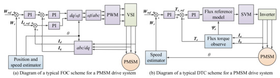
Figure 1. Control diagrams of typical FOC and DTC for PMSM drive systems. Note: Id and Iq stand for the d- and q-axis currents, respectively. Ye is the flux, Te the torque. For FOC, the d-axis current is set to zero for achieving the maximum torque per ampere. The current/torque loop and speed loop are set as feedback loops to keep the reference speed Wref as well as to make a smaller d-axis reference current Id_ref.
The ever-developing modern industry has contributed to the widespread investigations of modern control strategies, among which the SLC, SMC, ARC and MPC are the most studied and widely used methods. To save costs and reduce the impacts of external disturbances on sensors, SLC was proposed to obtain the rotor position through calculation instead of sensors. So far, estimation methods using an open loop, fuzzy adaptive algorithm and observer can be used for rotor position when the machines work at relatively high speeds, while high frequency signals are often employed to predict the rotor position in low-speed conditions [31][32][49,50]. SMC, originally proposed by Utkin [33][51], possesses excellent features including simple algorithm derivation, a fast response speed and strong robustness for handling parameter uncertainties and external disturbances, which has been widely used in many plants. To guarantee and convergence properties and to relieve the chattering phenomenon, fractional calculus can be integrated into SMC for PMSM control [34][35][52,53]. Results in [34][35][52,53] showed the improved control performance of SMC, especially for dealing with the uncertain and nonlinear system, i.e., electrical drive systems. In combination with the functions of adaptive control in handling unstructured uncertainties and robust control in attenuating disturbances, Yao and Tomizuka presented ARC [36][37][54,55] and proved that it could handle both structured and unstructured uncertainties. In [38][56], Yin et al. presented an adaptive robust backstepping controller with an extended state observer, as shown in Figure 2, for the speed regulating drive system of a new-type hybrid drive wind turbine. Experimental results illustrated the excellent control performances under disturbances from both wind wheel and power grid ends. Taking advantage of the development of artificial intelligence, MPC with an advanced predictive algorithm was investigated and applied to electrical machines. This kind of control strategy does not need the fixed control model but has three basic parts. These are model prediction, iterative optimization and feedback correction. MPC has the merits of good robustness and dynamic performance used in complex industrial processes, but requires improvements in terms of stability, anti-interference ability and model adaptability [39][40][57,58].
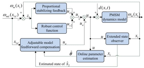
Figure 2. Control diagrams of ABC with ESO for PMSM drive systems [38][56]. Note: x1 = ωm, x1d = ωmd, θ = [θ1 θ2]T = [kt/J B/J]T. d(x, t) = TL/J and represents the lumped disturbances. ωm is the PMSM rotor angular velocity, TL the load torque or lumped disturbances, B the viscous friction coefficient, J the rotational inertia. kt = 1.5 pψf, and p is the number of poles, ψf the flux linkage of permanent magnet.
In industrial application, engineers should choose the control strategy and the matching processors according to the machine characteristics and operating scenarios to guarantee the best control performance and price/performance ratio. Meanwhile, more and more innovative control methods for PMSM drive systems will be presented based on the development of modern control theory, which will break through the limitations of traditional controllers and achieve parameter identification & control more easily by using artificial intelligence algorithms.