Your browser does not fully support modern features. Please upgrade for a smoother experience.
Please note this is a comparison between Version 1 by Zhan Xu and Version 3 by Beatrix Zheng.
According to the specific requirements of railway engineering, a techno-economic comparison for onboard hydrogen storage technologies is conducted to discuss their feasibility and potentials for hydrogen-powered hybrid trains. Physical storage methods, including compressed hydrogen (CH2), liquid hydrogen (LH2), and cryo-compressed hydrogen (CcH2), and material-based (chemical) storage methods, such as ammonia, liquid organic hydrogen carriages (LOHCs), and metal hydrides, are carefully discussed in terms of their operational conditions, energy capacity, and economic costs.
- hydrogen
- storage technology
- techno-economic analysis
1. Compressed Hydrogen Storage
Currently, compressed gas hydrogen technology is the most well-established among all the hydrogen storage technologies. It involves the physical storage of compressed hydrogen in high-pressure vessels and operates at high pressures, as high as 70 MPa. Its mature upstream and middle supply chain, including the production plants and refuelling stations, enable high-pressure hydrogen refuelling with relatively fast speeds and strong compatibility for vehicles. There are four standard types of CH2 vessels, as shown in Table 1:
| Type | Materials | Features | Typical Pressure (MPa) | Cost (USD/kg) | Gravimetric Density (wt%) |
|---|
| Cost Metric | Units | 35 MPa | 70 MPa | 2020 Targets |
2025 Targets |
Ultimate |
|---|---|---|---|---|---|---|
| I | All-metal construction | Heavy, internal corrosion | 17.5–20 | 83 | 1.7 | |
| II | All-metal hoop-wrapped composite cylinders | Heavy, short life due to internal corrosion | 20–30 | 86 | 2.1 | |
| III | Fully wrapped composite cylinders with metallic liners | Lightness, high burst pressure, no permeation, galvanic corrosion between liner and fibre (CF) | 35–70 | 567 | 5–5.5 | |
| IV | All-composite construction | Lightness, lower burst pressure. High durability against repeated charging. Simple manufacturability | 35–70 | 633 | 5–5.7 (Toyota data) |
Because of the low H2 gravimetric capacity of Type I and Type II, they are not suited for vehicular use. Type III and type IV vessels are widely employed for H2-powered vehicles now. Type III vessels are composed of a metal liner with full composite overwrap, generally aluminium, with a carbon fibre composite. Type IV vessels have an all-composite construction featuring a polymer (typically high-density polyethylene) liner with carbon fibre or hybrid carbon/glass fibre composite. Type III cylinders with 35 MPa storage pressure are usually equipped on heavy-loaded vehicles, from commercial buses, trucks, to locomotives. Type IV cylinders with 70 MPa storage pressure are employed for light-duty vehicles, mostly cars, such as the Toyota Mirai. A comparison between the two storage pressure types is shown in Table 2:
Table 2.
Summary results of assessment for CH
2 storage system compared to DOE targets
| System gravimetric capacity | Wt % | 5.5 | 5.2 | 4.5 | 5.5 | 6.5 |
| System volumetric capacity | g-H2/L | 17.6 | 26.3 | 30 | 40 | 50 |
| Storage system cost | USD/kWh | 15.4 | 18.7 | 10 | 9 | 8 |
| WTT efficiency (LHV) | % | 56.5 | 54.2 | 60 | 60 | 60 |
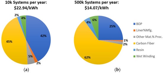
It can be found from Table 2 that the system gravimetric capacity of CH2 technology can mostly meet requirements of DOE (2025), but its system volumetric capacity is still far from the final target. Another unexpected result is that the gravimetric capacity of a 70 MPa storage vessel is less than that of a 35 MPa system. To withstand higher pressure, more CF must be wrapped around tanks, which increases its self-weight and raises its cost. Reducing the storage system cost is another focus point on the aspect of the industrial mass production. As shown in Figure 1, cost of CF and balance of plant (BOP) accounts for a large proportion of the total cost. Hopefully, it is predicted by DOE that the system cost will drop from 22.94 USD/kWh (10 k systems per year) to 14.07 USD/kWh (500 k systems per year).
Recently revealed hydrogen-powered trains all adopt CH2 hydrogen storage technology, including HydroFLEX (2019) [6][7][8][9][6,16,45,46], CRRC (2021), and Coradia ilint, Alstom (2018) [10][11][47,48], as shown in Table 3.
Table 3.
Recently revealed hydrogen-powered trains.
| Hydrogen-Powered Trains | HydroFLEX 1.0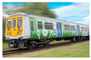 |
CRRC Datong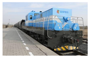 |
Coradia iLint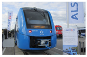 |
|---|---|---|---|
| Manufacturer | Porterbrook and University of Birmingham, UK, 2019 | CRRC, China, 2021 | Alstom, Germany, 2018 |
| Type | Passenger locomotive | Freight locomotive | Passenger train |
| Hydrogen storage method | 35 MPa CH2 vessel | 35 MPa CH2 vessel | 35 MPa CH2 vessel |
| Fuel cell | PEMFC (400 kW) | PEMFC (400 kW) | PEMFC |
| Auxiliary power | Battery (400 kW) | Battery (1000 kW) | Battery |
A key issue for CH2-powered train designs is the arrangement for mounting its new power system, including the hydrogen storage system, fuel cell system, auxiliary power, electric motors, etc. A large space is required to place high-power proton exchange membrane fuel cell (PEMFC) stacks, as well as the hydrogen storage system. Because of requirements for long range use, quantities of hydrogen must be taken to ensure enough power is provided. The drawback of the hydrogen storage capacity of CH2 results in multi-groups hydrogen tanks needing to to be installed. To tackle the problem of space arrangement, the Coradia ilint train places PEMFC stacks and hydrogen tanks above its carriages, as shown in Figure 2. HydroFLEX 1.0 changes its original PMOS carriage to a power system carriage, as shown in Figure 3, installing fuel cell systems, four Luxfer W205N Type III hydrogen tanks, batteries, control system, and electric motors, etc. The arrangement reduces passenger accommodation, but it is deemed to be within tolerance for passenger crush loading. Noticeably, the next-generation HydroFLEX will use more hydrogen storage tanks to enlarge its range, which has a considerable influence on the space assignment. Miniaturisation and lightweight design for the power system is necessary for current locomotives, but it is still a problem remaining to be solved with current CH2 storage technology.
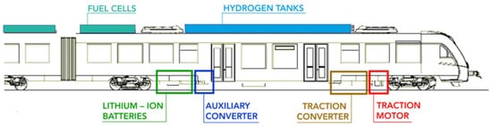
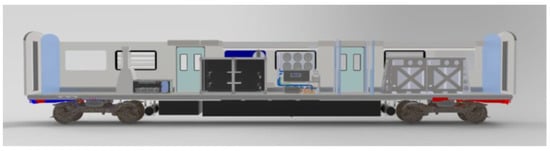
Figure 3.
Design of HydroFLEX’s pantograph motor open second (PMOS) carrier.
To summarise, compressed gas hydrogen storage technology is unmatched in the aspect of maturity, which makes it the most popular for onboard applications now. Nevertheless, low hydrogen capacity will restrict its further application on heavy-load locomotives. The requirements of long-range and high-power heavy haul railways result in the locomotive needing to be equipped with multiple groups of hydrogen tanks. This brings a larger space occupation and complex gas supply line, which affect its safety, stability, and economics. Enlarging its storage density and reducing its cost will continuously be important research points in the future.
2. Liquid Hydrogen Storage
Historically, liquid hydrogen storage technology has been the preferred method to increase hydrogen density for bulk transport and storage [13][50]. The density of liquid hydrogen is 70.78 kg/m3. Current technology can refrigerate hydrogen to a temperature of 20 K to be stored in vacuum-insulated vessels at 0.6 MPa [14][51]. It has great superiority over CH2 storage on the system volumetric storage capacity, which can reach up to 36.6 kg/m3. Another typical advantage of LH2 is its relatively low cost in most aspects. DOE presented a report in 2020, which compares the cost of the whole industry chain between CH2 and LH2 based on some specific scenarios as shown in Table 4. Indeed, the liquefication process consumes large quantities of energy. Moreover, LH2 costs less than CH2 in other processes. Fortunately, according to R.K Ahluwalia [15][52], large scale production with large plants will reduce its production cost, the liquefication capital cost will drop to 2500 USD/kg per day when its yield finally rises to 100 k tons per day.
Table 4.
Cost comparison between CH
2
and LH
| Pathway | H2 Production | Storage (Plant) | Liquefaction | Terminal | Transmission | Distribution | Dispensing (LDV) | Total Cost |
|---|---|---|---|---|---|---|---|---|
| CA(CH2) | 1.64 | 0.23 | - | 1.14 | - | 0.89 | 2.27 | 6.17 |
| CA (LH2) | 1.64 | - | 2.86 | 0.31 | - | 0.30 | 1.94 | 7.05 |
| TX to CA (LH2) | 0.89 | 0.31 | 2.15 | 0.33 | 1.10 | 0.30 | 1.94 | 7.02 |
Considering its energy storage density, cryogenic liquid hydrogen storage is an ideal method for heavy-duty vehicles. However, its gravimetric capacity is not completely satisfactory, owing to the high demand for insulation. Thick thermal insulation materials need to be wrapped in an LH2 vessel, causing a large cost, space, and gravity occupation. Moreover, the liquefaction process requires 4–10 kW/h per kilogram, accounting for over 30% of the energy stored, theoretically, more than twice than H2 compression. This percentage is even higher while in practical production. Another challenge for LH2 application is that it is difficult for long term storage, with 0.2–0.3% d-1 loss in well-insulated tankers and up to 3% d-1 in vehicle-mounted vessels [17][54]. Under cryogenic conditions, spontaneous ortho-to-para conversion would release non-negligible heat, e.g., 702 kJ/kg at 20 K [18][55], which would promote hydrogen evaporation. Although well insulated, absorbing heat from the atmosphere is unavoidable because of the huge temperature difference between the inner tank and the atmosphere. Inner pressure rises quickly as LH2 vaporises. Venting measures must be taken to prevent danger. Furthermore, more attention should be paid to its refuelling technology. The gas–liquid two-phase flow exists while filling, which slows its filling speed. It is a non-negligible problem when LH2-powered systems are mounted on locomotives [19][56].
LH2 is always mentioned in hydrogen transport because of its high H2 capacity and low transport cost, especially in marine environments. In 2019, Kawasaki Heavy Industries, Japan, launched the world’s first liquid hydrogen transport ship, Suiso Frontier [20][57]. It has a mounted 1250-cubic-meter, vacuum-insulated double-shell-structure stainless steel LH2 cargo tank, specially developed by Harima Works.
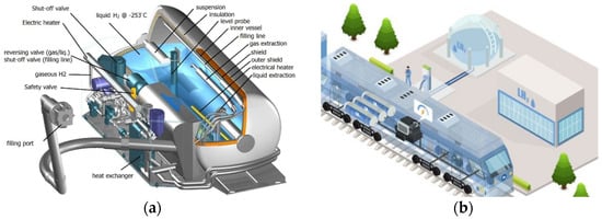
There are no existing LH2-powered locomotives yet, though LH2 has been used in the military and aerospace fields for a long time. The onboard LH2-based system is well established by Linde as shown in Figure 4. Therefore, LH2-powered trains can be considered as a great challenge, as well as a commercial opportunity. This is noticed by some institutions and corporations, such as the Korean Railroad Research Institute (KRRI) and Wabtec from the US [21][58]. KRRI announced details of a project to develop the world’s first liquefied hydrogen-based traction system in 2021. The project aims to develop a liquefied hydrogen hybrid propulsion system, high-insulation cryogenic storage technology, and a fast-refuelling technology. The LH2-fuel cell system will support operation at up to 150 km/h and offer a range of 1000 km as well as reduce refuelling times by 20% compared with 70 MPa compressed hydrogen trains. Similarly, in heavy-duty fields, a prototype long-haul truck named Mercedes-Benz Trucks-GenH2 [22][59] received approval from German authorities for road use, with a range of up to 1000 km.
From a technical point of view, LH2 storage technology is favourable for its high storage capacity, especially for heavy-loaded vehicles. Because of the large liquefication consumption and short dormancy time, much effort is needed to conquer these challenges for onboard applications. Additionally, transporting hydrogen over a long range by LH2 technology is a good choice and is feasible because of its high purity and hydrogen capacity. Comprehensively speaking, rail transit equipment based on LH2 is basically consistent with heavy-duty vehicles in the equipment route of hydrogen filling and supply. Due to the higher requirements of power, longer endurance, and lower refuelling flexibility of railway transit equipment, higher demand on hydrogen storage efficiency is raised to reduce the filling frequency. Under the premise of the complete LH2 infrastructure, setting up special LH2 refuelling equipment along the track to provide special filling services is an important prerequisite for the development of LH2 railway transit.
3. Cryo-Compressed Hydrogen Storage
Cryo-compressed hydrogen storage (CcH2) refers to the storage of H2 at cryogenic temperature in a vessel that can be pressurised (nominally 25–30 MPa) [24][25][26][61,62,63].
Lawrence Livermore National Laboratory (LLNL), California, developed a novel CcH2 vessel and the onboard storage and supply system for fuel cell stacks [27][28][29][24,64,65]. Temperature and pressure management of this system is carefully treated because of the high-pressure and cryogenic characteristics of CcH2. Compared to the Type III 35 MPa H2 system, the 50 MPa CcH2 storage system can achieve 91%, 175%, and 21% improvement in gravimetric capacity, volumetric capacity, and system cost reduction, respectively. Meanwhile, it enables the loss-free dormancy exceeding over 7 days with an initial 85% load. According to these attractive performances, many researchers participate in promoting the development of CcH2 technology [30][31][32][66,67,68]. Optimisation designs for onboard CcH2 storage systems are made to enlarge its energy utilisation efficiency. LLNL and Argonne National Laboratory (ANL) have made simulations for CcH2 storage systems for freight and regional locomotives to validate their feasibility in railway engineering. With the annual production of CcH2 systems rising to 500 k, its system cost will reduce to 14.93 USD/kWh [33][69]. BMW AG (Munich, Germany) released its prototype cryo-compressed cars for testing, as shown in Figure 57. The vessel was tested by LLNL from 2017 to 2018. No degradation of the vessel was observed after 1000+ cycles to 30 MPa [34][35][70,71].
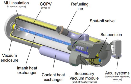
Figure 57.
Schematic of CcH
2
storage vessel from BMW.
Detailed cost comparison among CcH2, CH2, and cold-cH2 has been conducted by DOE, 2018 [36][72]. The results are shown in Table 5. It can be seen that 350 bar and 500 bar CcH2 storage vessels have a price advantage compared with 350 bar CH2 storage vessels because of its lower requirement for composites (mainly CF).
Table 5.
Storage system cost comparison between CH
2
, Cold-cH
2
, and CcH
2
(USD/kWh).
| 350 Bar CcH2 | 500 Bar CcH2 | 700 Bar CcH2 | 350 Bar CH2 | Cold-CH2 | |
|---|---|---|---|---|---|
| Liner | 1.03 | 1.01 | 0.99 | 0.21 | 1.58 |
| Composite | 3.25 | 4.70 | 7.12 | 9.79 | 8.86 |
| Insulation and containment vessel | 3.48 | 3.21 | 2.92 | 0.00 | 3.05 |
| BOP | 3.84 | 3.85 | 3.85 | 3.25 | 3.45 |
| Assembly and other | 0.04 | 0.04 | 0.04 | 0.12 | 0.04 |
| System cost (USD/kWh) |
11.65 [−2.32, +2.90] |
12.82 [−2.32, +2.90] |
14.92 [−2.78, +3.61] |
13.38 [−3.44, +5.73] |
16.97 [−0.81, +1.59] |
To conclude, CcH2 storage combines the advantages of CH2 storage and LH2 storage, which results in a high hydrogen storage capacity and long loss-free dormancy time. Core components of the CcH2 storage system have experimentally validated the requirements of high-density storage, rapid refuelling (without H2 loss), safety, and structural durability. However, this technology is still in its prototype stage. Relevant international standards need to be formulated. Infrastructure and supporting facilities will reduce its cost in the future. It can be forecasted that CcH2 is a prospective option for hydrogen-powered hybrid trains in the future.