Your browser does not fully support modern features. Please upgrade for a smoother experience.
Please note this is a comparison between Version 1 by Ioan Sarbu and Version 3 by Catherine Yang.
Renewable energy is derived from non-exhaustible and naturally renewable natural resources. Solar, geothermal, wind, biomass, and hydropower are examples of RES. Romania offerenewable s an excellent mix of solar, geothermal, hydroelectric, and biomass energy sources (RES)potential. Solar, geothermal, and biomass resources are the most appropriate renewable energies for heating/cooling.
- district heating
- distribution network
- low-temperature
- solar energy
1. Solar Energy
In recent years, scientists’ interest in solar energy has increased. For solar energy to be utilised, it must convert into other types of energy. Principal uses for solar technologies require low-temperature heat, such as space heating, domestic water heating, pool heating, and some industrial processes.
1.1. Solar Thermal Systems
The solar collector is the essential component of a solar system. ST collectors are a subset of HXs that use a heat transfer fluid (HTF) to convert solar light into thermal energy. There are several ST collectors available on the market [1][26].
Generally, a system for transforming solar energy to thermal energy consists of the following components (Figure 14): solar collectors (panels); heat storage schemes; circulating pumps; a heat transmission and distribution network; and automation, control, and safety equipment [2][50]. This system can provide heat for space heating and DHW production. If solar energy is insufficient, a secondary energy source is utilised.
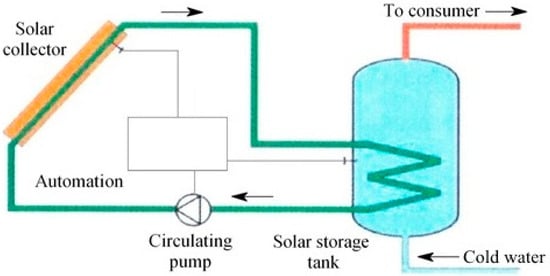
Figure 14. Conversion of solar energy to thermal energy.
The solar fraction (f) is the proportion of the total thermal load fulfilled by solar energy and is calculated as follows:
where Qsol is the solar energy provided to the system, in kJ, and Qaux is the auxiliary energy, in kJ.
f=QsolQsol+Qaux
A solar combisystem (SCS) offers both solar space heating/cooling and hot water from a single array of ST collectors, often supplemented by a non-solar heat source [3][51]. Europe has the most developed solar thermal applications market [4][52]. The yearly space heating contribution in ultra-low energy buildings may range between 10 and 60%, depending on the size of the SCS used. Table 14 provides a summary of the primary SCS studies in the literature.
Table 14.
Some literature studies on SCS.
| Authors | Year | Research Subject | Outcomes |
|---|---|---|---|
| Weiss [5][53] | 2003 | Academic publication | Fundamentals of the system |
| Andersen et al. [6][54] | 2004 | SCS thermal performance in various climates | The thermal performance of an SCS is mainly determined by the energy balance |
| Kacan and Ulgen [7][55] | 2012 | Monthly energy savings are between 59 and 89%. The annual solar fraction (f) value is approx. 83% | |
| Asaee et al. [8][56] | 2014 | Different areas in Canada have f values ranging between 32% and 93% | |
| Ellehauge and Shah [9][57] | 2000 | Different system designs in the market | 33 to 50% is used for DHW, and the most typical system layout is two closed flow cycles for space heating and DHW |
| Kacan [10][58] | 2011 | Doctoral Thesis | f fraction values range from 10 to 100% |
| Hin and Zmeureanu [11][59] | 2014 | System optimisation | The payback periods (5.8 to 6.6 years) for various system configurations are unacceptable. |
Solar DH is the supply of central heating and hot water utilising solar energy through a system in which water is heated by the ST collector field and distributed via DH pipe networks. DH is best appropriated to locations with a large population, construction density, and colder weather. Solar collectors can be put on the ground for DHSs.
Solar DHSs can provide heat to buildings supplied from the secondary circuit via DH substations or can be connected to the return pipe of the DH primary circuit in HS. DH has advanced substantially over the past few decades, considered the most effective technology for heating a building’s interior. Some studies concentrated on the coupling of DH and CHPs, renewable energy (solar and geothermal heat, or HPs), and industrial heat recovery [12][13][14][15][9,60,61,62].
1.2. Solar Photovoltaic Systems
Solar PV systems provide a safe and ecologically sustainable energy source, among other advantages. In tandem with conventional power plants, PV-based electricity generation has increased fast worldwide during the past two decades [16][63] in response to the rising demand for electrical energy. Solar PV production in most nations is contingent on the kind of policies implemented by that country.
Solar PV systems absorb light radiation (in the ultraviolet and visible spectrum) using PV cells integrated into solar panels to generate energy. PV systems can be network-disconnected (stand-alone) or grid-connected (on-grid).
While the typical output of a PV panel is direct current (DC) electricity, the vast majority of household and commercial electrical equipment utilise alternating current (AC). Consequently, a typical solar PV system has four fundamental components (Figure 25): PV panels, a battery, an inverter, and a vapour-compression AC unit [17][64].
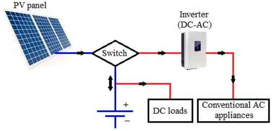
Figure 25.
Diagram of a stand-alone photovoltaic (PV) system.
The PV panel is composed of cells that allow photons to “knock” electrons out of a molecular lattice, releasing an electron and “hole” pair that diffuses across an electric field to separate contacts, so producing DC energy.
The battery stores DC voltages in a charging mode when sunlight is present and provides DC electricity in a discharging mode when sunlight is absent. A battery charge regulator may prevent the battery from being overcharged. The inverter is an electrical circuit that transforms DC electricity to AC and subsequently supplies the AC consumers with electrical energy. In reality, the vapour-compression AC unit is a regular heating or cooling system powered by an inverter.
The PV system can function as an independent, hybrid system (operating with an oil/hydro/gas power facility), grid or utility intertie system.
A photovoltaic/thermal (PV/T) hybrid collector transforms solar energy into electricity and heat. The energy performance of commercially available PV/T systems for electricity and DHW generation was examined in three European nations [18][65].
Demand for solar PV is growing and has become the most competitive option for power generation in multiple markets (for residential and commercial applications) [19][66].
2. Geothermal Energy
Geothermal energy is stored in the Earth’s crust. With increasing depth within the Earth’s crust, temperature, and pressure rise, geothermal energy may be more effective. Low-enthalpy geothermal resources (temperatures below 200 °C) are primarily employed for direct heating applications, whereas high-enthalpy geothermal resources (temperatures over 200 °C) are appropriate for power production. Even at the deepest depths, the temperature of the Earth remains largely stable throughout the year. Geothermal energy technology can play a crucial part in future sustainable DHC systems. Romanov and Leiss [20][31] classified geothermal systems based on geothermal fluid temperatures and their compatibility for different DHC generations, as shown in Table 25, where: EC—electric chiller; AC—absorption chiller.
Table 25.
Classification of geothermal systems.
| Geothermal Technology | Temperature of Wellhead Fluids | DHC Generation | Equipment to Feed Buildings | ||
|---|---|---|---|---|---|
| Space Heating | DHW | Cooling | |||
| Shallow | <25 °C | 5GDHC (ambient temperature) | HP | HP | EC/direct |
| Medium deep | 25–90 °C | 4GDHC (low temperature | HP/HX/direct | HP/HX/direct | AC |
| Deep | >90 °C | 2GDH and 3GDH (high and medium temperature) | HX/direct | HX/direct | AC |
Shallow geothermal systems can utilise either the heat of the ground (closed-loop systems) or the heat of the groundwater (open-loop systems). An HP is a fundamental component of a shallow geothermal system, and they currently dominate the direct use of geothermal energy.
Suppose a shallow geothermal energy system with insufficient heat output for specific uses. In this case, either additional boreholes must be dug to increase the necessary surface area, or the boreholes must be drilled deeper using medium-depth geothermal systems, which are ideal in an urban setting [21][67]. Deep geothermal energy generates electricity (by direct steam or Rankine organic cycle), heat, or electricity and heat [22][68].
2.1. Direct Use of Geothermal Energy to Provide Heat to Consumers
Romania possesses significant low-enthalpy geothermal resources ideal for direct heating utilisations [23][69]. Local systems are utilised to provide heat to small consumers close to the producing borehole and with a thermal load of 1–4 MW. For the heat supply for a group of consumers (a locality, a district) with a heat demand exceeding 5 MW, centralised systems are indicated. Figure 36 shows a scheme of the geothermal water circuit in a DHS.
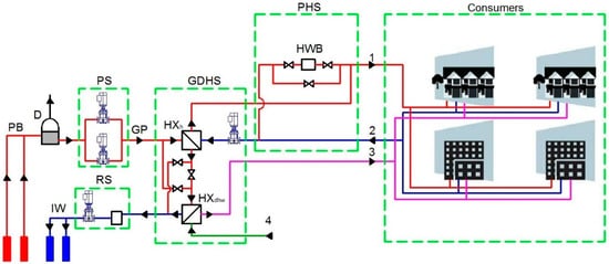
Figure 36. Schematic of a district heating system (DHS) utilising geothermal energy: PB—production borehole; D—degasser; PS—pumping station; GP—geothermal water pipe; GDHS—geothermal DH substation; HXh—heat exchanger for heating; HXdhw—heat exchanger for DHW; PHS—peak heating station; HWB—hot water boiler; IW—injection well; RS—reinjection station; 1, 2—pipes to and from heating installations; 3—DHW pipeline; 4—cold water pipes.
The source consists of one or more geothermal water production boreholes that supply the geothermal DH substation via a shared network. Here, the geothermal water transfers heat to the secondary heat carrier via HXs, before being re-injected into the deposit by injection wells.
The geothermal DH substation is coupled with a peak HS to maintain the required temperature of the heat carrier for consumers. The distribution network includes supply–return heating, DHW, and recirculation pipes.
As geothermal water is often highly mineralised, it is advised to isolate the primary circuit (geothermal water) from the secondary circuit (hot water from the heating system and the DHW production installation) through the HX for heating (HXh) and HX for DHW (HXdhw).
Through the HXs at the geothermal DH substation, the geothermal water provides the secondary heat carrier for the heating and DHW installations of the consumers. Convective heaters (cast iron radiators, sheet metal radiators, fan coils) require a high-temperature heat carrier (70–90 °C), while radiant heaters require a low-temperature heat carrier (40–50 °C).
There are 40 projects with direct use of geothermal energy reported in Romania, of which 12 are for the DHSs [24][70].
2.2. Heat Pump Systems
The HP is one of the most favourable HVAC systems to consider when integrating RES. The quantity of energy Eres absorbed by an HP that qualifies as RES must be determined using the following equation [25][71]:
where EU is the useful thermal energy supplied by HP, and SPF is its seasonal performance factor.
Eres=EU(1−1SPF)
Only HP with SPF > 1.15/η will be considered, where η is the total gross electricity output ratio to primary energy consumption for power generation. The average η for EU nations is 0.4, indicating that the minimum SPF should be 2.875.
An HP is based on a reverse Carnot cycle, which uses driving energy and generates a thermal effect. Any HP transfers energy ES from a low-temperature source ts to a high-temperature source tu while using driving energy ED.
A heat source may be
-
Air or a gas (exterior air, warm air, or hot gases);
-
Surface water, groundwater, geothermal, or hot waste water;
-
The ground, which has the advantage of being easily accessible.
The most popular HP systems are powered by electricity and have an electro-compressor. The working concept of an HP based on vapour compression is presented in Figure 47 [26][72].
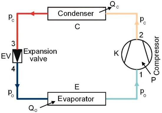
Figure 47.
Scheme of a heat pump (HP) using vapour compression.
A cycle of evaporation, compression, condensation, and expansion is required to raise low-temperature heat to above 38 °C and transport it indoors. A non-chlorofluoro- carbon refrigerant flows within the HP [27][73].
-
Energy efficiency. The implementation of an HP in a heating/cooling system depends on energy indices and economic analyses. In heating mode, the operating an HP is characterised by the coefficient of performance (COP), which is defined as the ratio of useable thermal energy Et to electricity consumption Eel:
COP=ES+EDED=EtEel
Seasonal coefficient of performance (COPseasonal), sometimes referred to as the SPF or yearly efficiency, is determined if, in Equation (3), both useable energy and spent energy over a season (year) are included.
The cooling performance is expressed by the energy efficiency ratio (EER), in Btu/h:
where 3.412 is the conversion factor between Watt and Btu/h. GSHP systems have heating COP values between 3 and 5.5 and cooling EER values between 10.5 and 20 [26][72].
EER=3.412×COP
-
Calculation of CO2 emissions. HPs powered by electrical energy derived from hydropower or renewable energy decrease GHG emissions, such as CO2, much more than HPs powered by electricity derived from coal, oil, or natural gas power plants.
If Et is defined as the yearly thermal energy delivered by HPs, then the yearly consumption of primary energy from HP electrical usage is given by:
Eel=EtSPF
The HP’s CO2 emissions during operation may be calculated as follows.
where gel is the electricity-specific CO2 emission factor. The average gel in Europe is 0.48 kg CO2/kWh, whereas, in Romania, it is 0.54 kg CO2/kWh [28][74].
CCO2=gelEel
-
Heat pump types. The most prevalent method of HP categorisation is based on the heat source. There are two primary kinds of HPs: air-source HP (ASHP) and ground-source HP (GSHP), which includes water-source HP (WSHP) and ground-coupled HP (GCHP) systems.
ASHP operates with ambient heat and is used in bivalent heating systems for cooling, heat recovery, and DHW generation. ASHP is less efficient than GSHP if the outside temperature falls below −10 °C.
The WSHP system employs water as a heat source and either air or water to transfer heat to the air conditioner. Surface water HP (SWHP) and groundwater HP (GWHP) are two classifications for these systems. In an SWHP system, heat rejection/extraction is accomplished by moving working fluid via high-density polyethylene (HDPE) pipes placed at the proper depth in a lake, pond, or reservoir. This kind is confined to warmer areas for HP operation in the heating mode. A GWHP is an open-loop system that collects groundwater from a well and transports it to an HP (or an intermediary HX) for an energy source [29][75]. Except for minor installations, direct systems (where groundwater is pumped directly to the HP) are not advised.
A GCHP system is a closed-loop system [30][31][32][33][76,77,78,79] comprised of a reversible vapour-compression HP connected to a ground heat exchanger (GHE) (Figure 58) and a heat distribution subsystem.
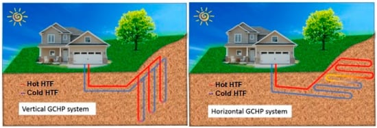
Figure 58.
Horizontal and vertical ground heat exchanger (GHE) system configuration.
A pump circulates a brine (antifreeze solution), as HTF, via the GHE (collector or borehole) and the HP. The GHEs frequently utilised in GCHP systems are composed of HDPE pipes. GHEs may be divided into two significant kinds based on their spatial arrangement: horizontal (0.8–1.8 m deep) and vertical (often 20–200 m deep) GHEs. Horizontal single-pipe GHEs consist of parallel pipes laid in trenches. Special GHEs, such as multiple pipes inserted in a single trench and spiral loops, were created to save the ground surface [34][80]. U-tubes and coaxial tubes are the two most prevalent configurations for vertical GHEs or borehole heat exchangers (BHEs) [35][81]. The annulus of a borehole is often backfilled with a specific substance (grout) that may prevent groundwater pollution.
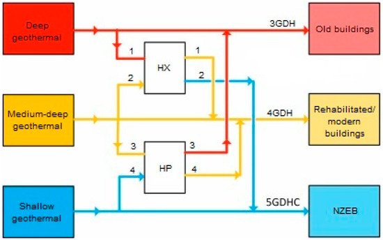
It was shown [36][82] that GCHPs are the dominant form of direct geothermal energy use. Multi-depth geothermal systems use geothermal energy from various depths to produce energy for heating; heating and cooling; or heating, cooling, and power [37][83]. Figure 69 depicts a simple geothermal system with several depths [20][31]. Deep geothermal systems feed old buildings by a 3GDH network, medium-deep geothermal systems supply rehabilitated or new buildings via a 4GDH network, and shallow geothermal systems serve NZEB through a 5GDHC network. Multi-depth geothermal systems are appropriate for districts with varying heating and cooling needs, such as residential and administrative buildings.
2.3. A Brief Overview of Previous Works
An economic and environmental study [38][84] revealed that DH based on a vertical GCHP system for a university campus in Spain is preferable to the current fossil fuel-based system. Another research [39][85] demonstrated that horizontal and vertical GCHP systems are less economical than UK gas boilers.
According to [40][86], the thermal performance of the double U-tube arrangement is 30–90% greater than that of the single U-tube configuration. Horizontal GHEs were extensively studied and simulated using analytical and numerical models [41][87] and computational fluid dynamics (CFD) [42][88] to compare linear and spiral systems. The findings revealed that horizontal helical systems are the most energy-efficient.
Pratiwi and Trutnevyte [43][89] investigated the environmental impact of shallow and medium-deep systems for heating/cooling on a large scale, revealing that geothermal systems with depths of 350–1600 m coupled to disperse HPs have the most negligible environmental impact. The energy and economic performance of various deep coaxial closed-loop systems configurations were analysed [44][90].
In the last two decades, more researchers examined the performance and applications of solar-assisted HP (SAHP) and GSHP systems. These technologies may be used to generate the solar-assisted GSHP (SAGSHP) hybrid system [45][91]. Yuehong et al. [46][92] performed experiments on a SAGSHP system in which the heating mode alternates between an HP powered by solar energy and a vertical GCHP. Ozgener and Hepbasli [47][93] experimentally evaluated the efficiency of a SAGSHP greenhouse heating system with a vertical GHE. Zongwei et al. [48][94] also examined a SAGSHP heating system with latent heat TES. They asserted that the latent heat TES might enhance the solar fraction of the system, increasing the COPsys.
Recent research [49][50][95,96] addresses integrating TES technology into the distribution network to decrease the required peak capacity, enhance renewable penetration, or improve efficiency.
3. Hydraulic Energy
As the oldest kind of RES utilised by humans, hydraulic energy can be found in potential energy (water-free fall) and kinetic energy (water flow). During this century, the global need for electricity will increase dramatically due to population growth and improving living standards in developing nations.
Currently, when fossil fuel prices and environmental protection costs continue to rise, micro-hydropower plants are now winning the competition to provide electricity to isolated localities and objectives.
In recent years, the recovery of excessive hydraulic energy from DH networks, especially urban water networks using micro-hydropower technology, has been considered [51][52][53][54][55][56][57][97,98,99,100,101,102,103].
The network hydraulic regime is determined by water discharge, pressure, and the components’ hydraulic characteristics. Expanding a DHS involves increased water pressure at the heat source node, often necessitating pressure reductions at network nodes or main pipes. Traditionally, the only way to reduce pressure is to use pressure-reducing valves (PRVs), which release excess energy. This situation creates a possibility to recover energy, identified by analysing piezometric graphs, using micro-hydropower technology with pumps operating as a turbine (PATs). The electricity thus produced supplies the electricity grid. Piezometric graphs show the distribution of water pressure in the network for heat sources, pipes, and nodes, considering the geodetic profile and the network route.
PATs are micro-hydro turbines mounted in the urban water supply or heating systems in places where pressure adjustment is advantageous or necessary. PRVs and PATs are similarly exploited to maintain downstream pressure. Generally, a PRV is mounted in parallel with a PAT to bypass surplus discharges the turbine capacity and support the system’s operation during turbine maintenance [58][104]. Typical locations of PATs are directly downstream of DH substations or on the main pipe (Figure 710). The optimal locations of the PATs can be determined using optimisation models [54][100].
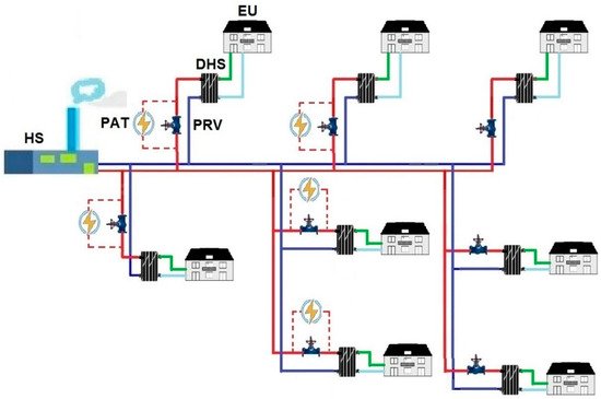
Figure 710. Typical micro hydro-turbine locations in a DHS: HS—heating station; PRV—pressure reducing valve; DHS—district heating substation; EU—end-user; PAT—pump as turbine.
The installation of PATs in DHSs generates electricity, reduces water and heat losses in the system, minimises the impact on the environment, and eliminates the need for geological and hydro-geological studies of the site.