Your browser does not fully support modern features. Please upgrade for a smoother experience.
Please note this is a comparison between Version 2 by Catherine Yang and Version 1 by CHONG TAK YAW.
Switchgear is generally known as a switching device. It is used for circuit isolation and the protection of power systems from overload and system faults. The definition of switchgear also includes devices that are utilized to regulate, meter, and control power systems. The term refers to switching and interrupting devices, as well as their combinations with control, instrumentation, metering, protective, and regulating devices, as well as the components of devices involved in dealing with interconnections, items, and supporting structures, which are used primarily in the generation, transmitting distribution, and conversion of electrical power.
- fault detection
- medium voltage
- partial discharge
- switchgear
1. Corona
Corona is the faint light that surrounds an electrical conductor caused by the ionization of air when nitrogen in the air breaks down. When nitric acid is mixed with moisture, nitric acid is produced. This acid also destroys insulating materials and metallic mechanisms, potentially causing heat difficulties. The most hazardous element is that it occurs without causing a flashover because corona formation happens when nearby air is strained past its ionization threshold and occurs virtually quietly. When electrical stress surpasses the insulative properties of air (as illustrated in Figure 71), the air across the layers of the insulating becomes charged. Corona finds its way to Earth, as seen in Figure 71 [1][2].
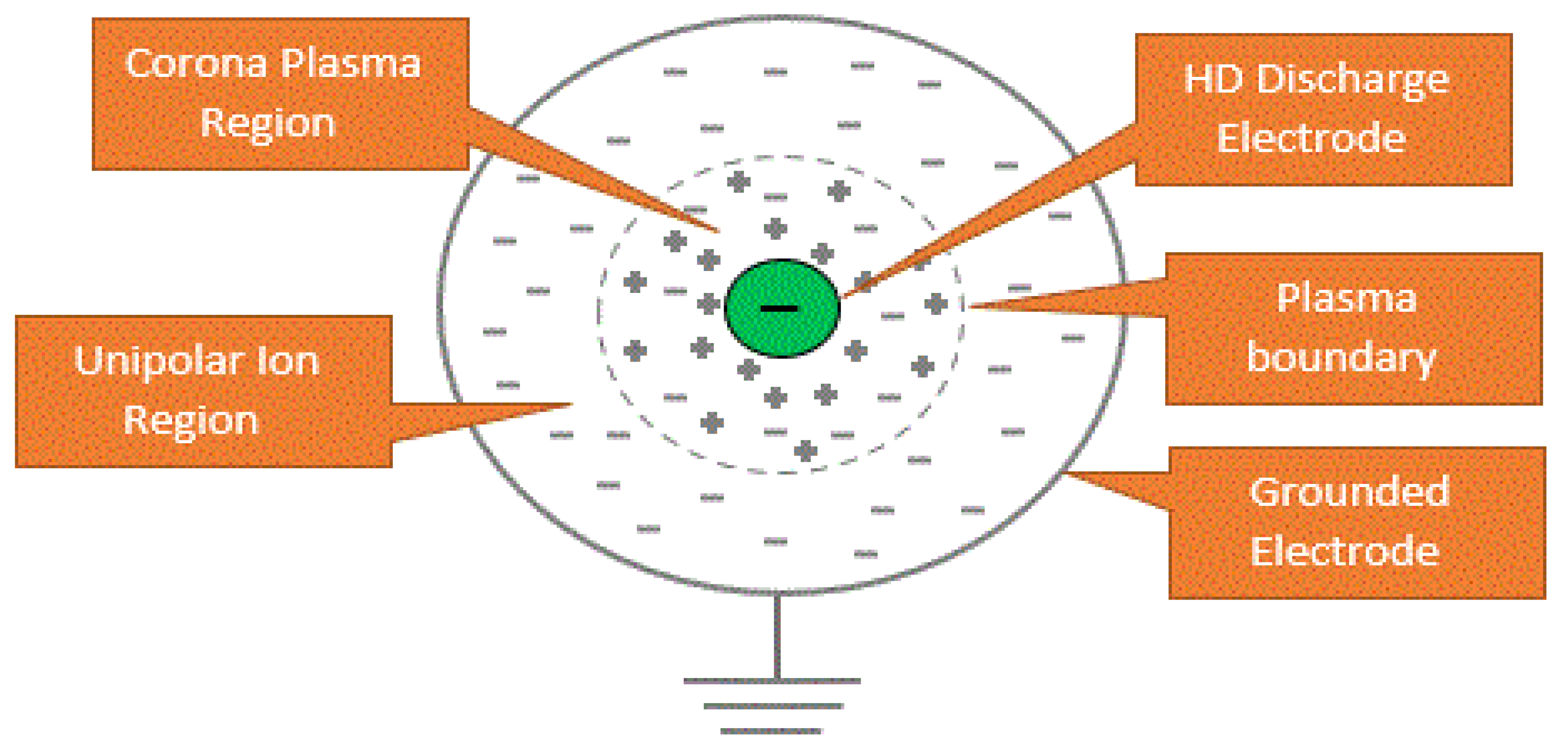
Figure 71. Process of ionization.
Corona discharge occurs when a neutral atom or molecule is exposed to a high-voltage gradient, which ionizes it and starts an avalanche process [2]. When there is no use of shock in managing electric field intensity, high-voltage equipment may experience the spontaneous occurrence of instantaneous corona discharges. A corona can be created in instances where there is a strong electric field around the conductor, which can generate a conduction band. Although it does not have the strength needed to simply produce an electrical discharge in a device, there is a breakdown or arcing, as presented in Figure 82a–c.
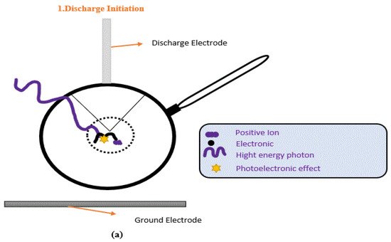
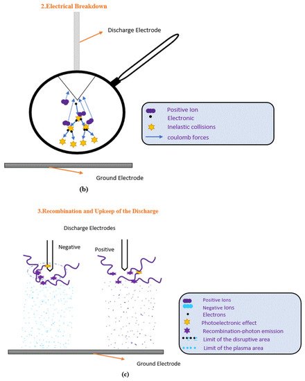

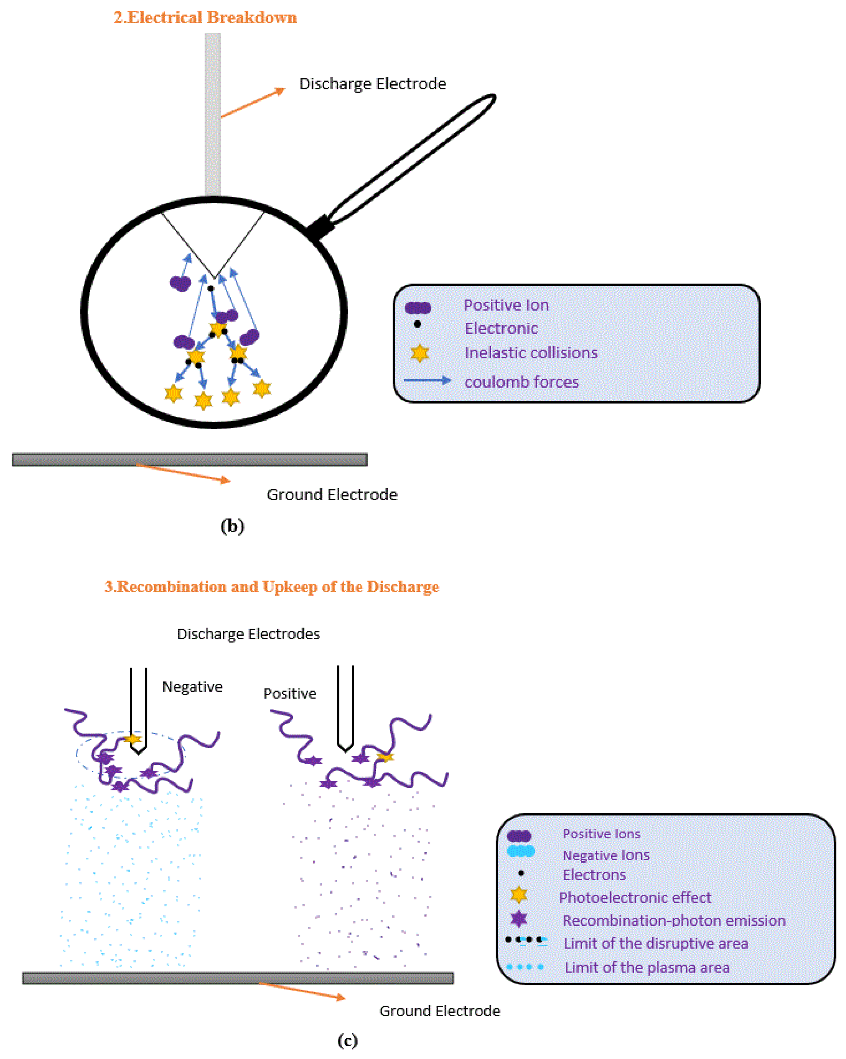
Figure 82. (a–c) A corona discharge is a phenomenon that occurs in the air.
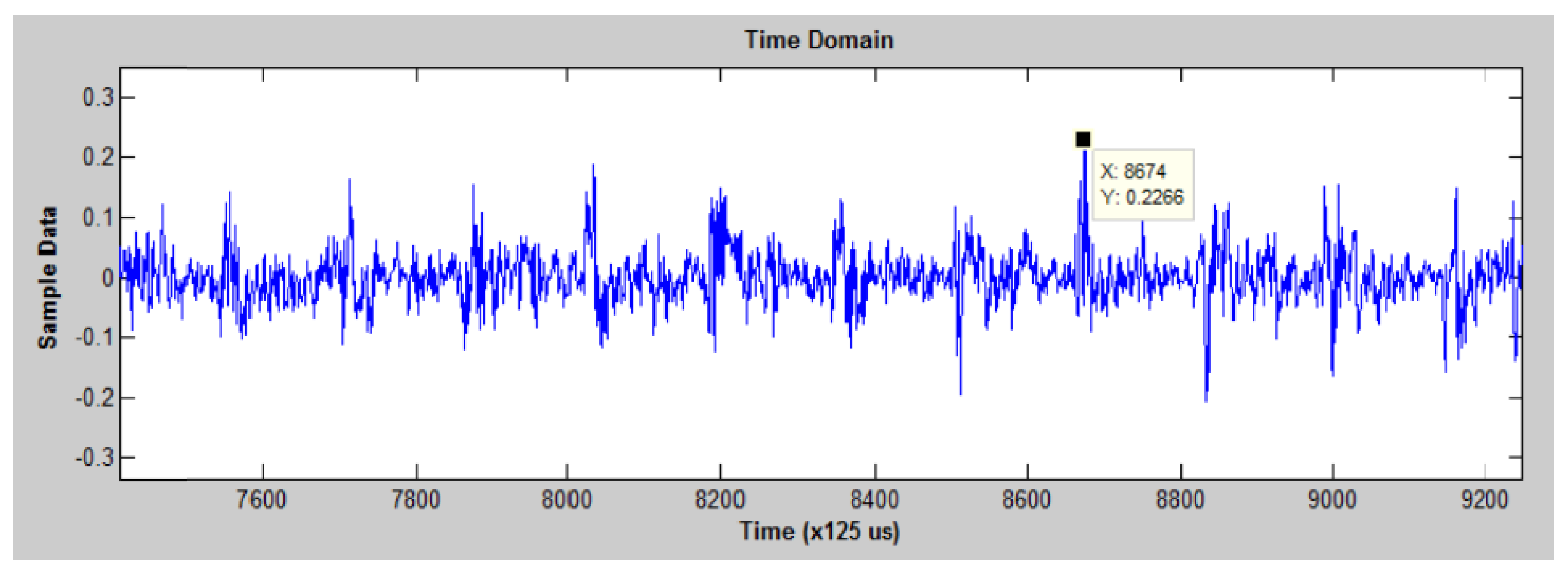
The conductance and avalanche processes are influenced by the electrode material. Highly conducting materials generate a strong electric field, energizing a large number of free electrons and causing severe corona discharge defects. Copper (Cu) and stainless steel (SS) are two of the most common metals used in MV switchgear because they are both more conductive and more durable than other metals and have a conductivity of 5.96107 siemens per meter (S/m), which is greater than that of SS, which is 1.45106 (S/m). Cu, in comparison to SS, causes more corona discharges in MV switchgear under high-voltage stress. Air, known to have molecules that are electrically neutral, is an insulator. There is an alteration in the molecules whenever energies of high magnitude flow as electrons from an electrode and collide with molecules. Energy is absorbed by the electrons around the atomic nuclei; these electrons transition to high energy levels and separate from their constituent atoms or molecules, leaving a positively charged ion and a dissociated free electron. This avalanche process creates a mix of electrons and ions, as new electrons are created by electrons that have been hit by other electrons [3]. As a consequence, another condition for corona discharges is the presence of light indicators of strong locally applied electric fields that enable persistent discharge into the atmosphere [4]. Moisture plays an important role, such that when a value in air or gas is surpassed, a corona discharge develops, resulting in the formation of ozone and ultraviolet, oxides of nitrogen, sound, electromagnetic emission, and nitric acid. Ozone is a pungent gas that causes rubber-based insulation to fade. Violent nitric acids may occur when there is a lot of moisture or humidity in the air; they target specific metallic compositions, such as copper and other metals, as well as most dielectrics, producing corrosion. Furthermore, tremendous energy from certain discharges causes mechanical, electric, and thermal damage [5]. The electromagnetic emission may be recognized as a disturbance on amplitude-modulated (AM) radios, and the corona sound can be recognized by human ear and ultrasound monitoring instruments. As seen in Figure 93, spectrum analysis software may be used to view the recorded ultrasonic signatures of a corona’s wave pattern. The sounds of the corona are akin to those of frying, torrential rain, or a continual buzzing sound [6].
Hence, a corona, for example, signals voltage difficulties and may persist without current flow due to its primary source, which is high potential inside the electric current. The negative (−) and positive (+) positions of a 60 hertz (Hz) rotation have the most corona effect. Corona problems are caused by three basic causes:
-
Spatial factors;
-
Geometric factors;
-
Contamination.
Insulation boards, narrow air gaps among conductors, and switching cabinet components all have these spatial characteristics, which may be caused by the following:
-
Grounded surfaces interact with non-shielded cables.
-
Conductors are tie-wrapped together.
-
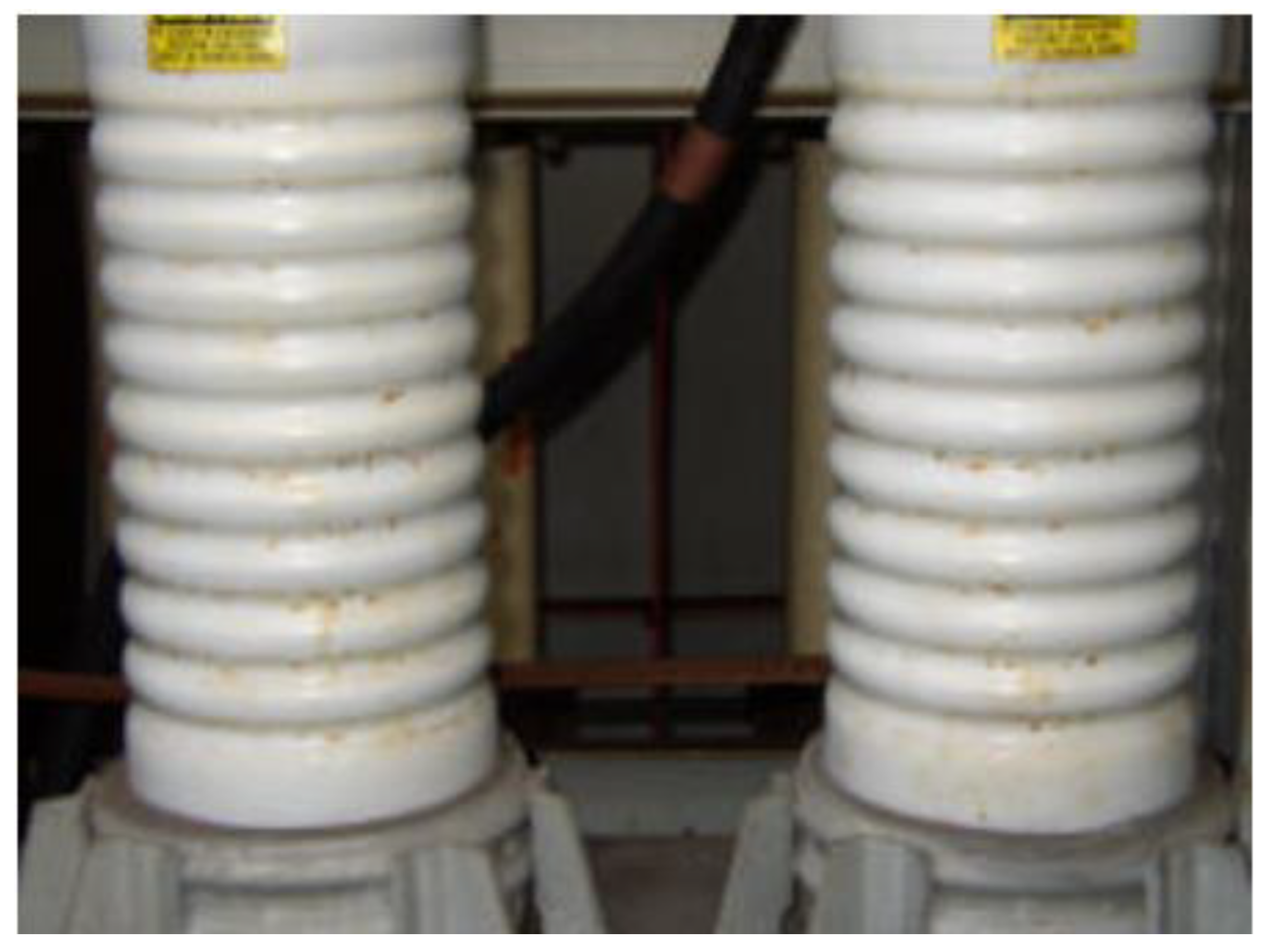
Busbars are close to the insulator material, and contamination is present on ceramic (an example is shown in Figure 104, [7]).
-
Conductors touch the edges of cabinets, insulators, and conduits.
2. Tracking
Tracking (also known as “baby arching”) traces the path of dirty insulation and deterioration over the exteriors of modules. In another way, when the corona is turned on, it creates a conducting mist of air surrounding itself and leaves a conductive path on the exterior. With high-voltage and MV components, tracking occurs such that a carbon track forms on the insulator and conductor. As a result, the time it takes for short-circuit or overheating is determined by the distance between the ground and the phase. Figure 115a,b depicts carbon tracks on insulators in the switchgear compartment caused by a- and b-phase fuses [7][8].
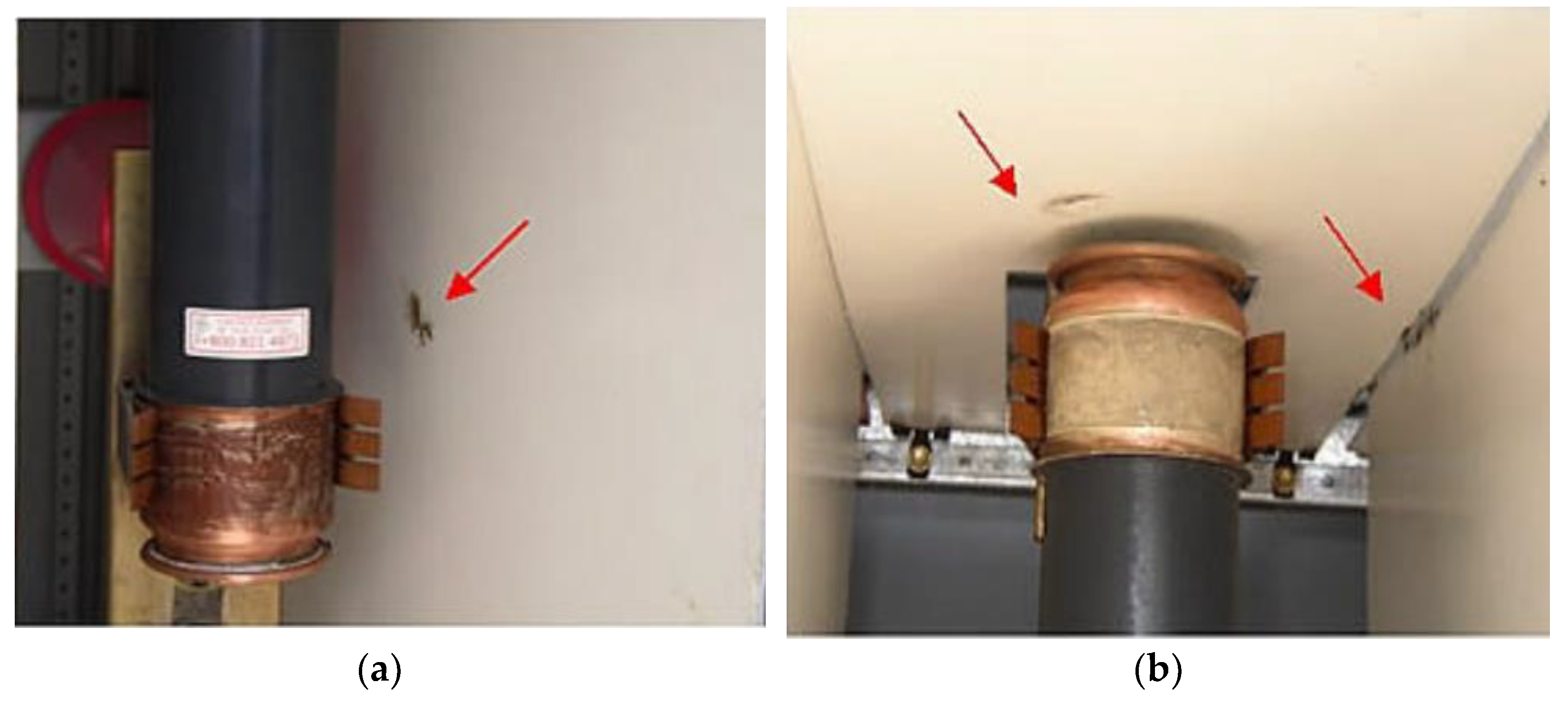
Figure 115.
(
a
,
b
) show between a-phase and b-phase fuses; carbon trails may be seen on the insulation
[7]
.
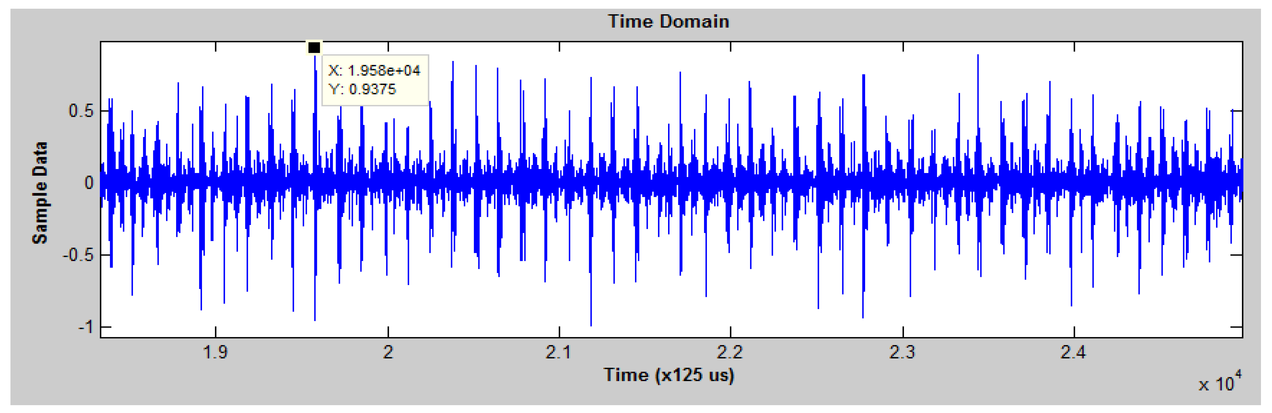
The recorded ultrasonic signature of the tracking’s wave pattern can be seen using spectrum analysis software, as shown in Figure 12 [8].
From an engineering point of view, tracking is the progression of the creation of a solid channeling track over the exterior of the insulation caused by exterior erosion under voltage application. This incident occurs in all types of polymeric insulators (PI), both indoor and outdoor applications. PIs are always in contact with moisture and/or dust and create a conduction film on the outer layer. During the operation of the PIs, the film begins conducting and causes dryness to the outer layer due to the heat generated. The film then creates sparks, and an insulation fiasco occurs when the whole film is carbonized [9]. Tracking can be identified as a constant buzzing noise with sporadic crackling. The noise is almost similar to that of the corona but has gaps and likely drops in concentration. However, it can swiftly steer to arcing due to further damage when tracking is not altered [10].
In this study [11], the process of tracking was divided into four phases based on the experimental discharge phenomena, discharge automatic methods phase diagrams, and corrosion degree of materials: commencement, safety, development, and outbreak. The micromorphology of the materials was studied using a scanning electron at various phases of tracking. The findings revealed that when surface morphology changes and surface products develop during tracking, the amount of the Carbonyl (C) attribute in the material’s spherical area declines first, then grows, whereas the amounts of oxygen (O) and SuperADM Interferometer (Si) increase first and then decrease. The epoxy group of the material decomposes over time. During the outbreak stage, a carbonyl group is formed on the material’s surface, which subsequently degrades. Furthermore, the processes of thermal aging and tracking degradation vary. Thermal aging allows for easy electron injection into the materials during tracking, lowering the material’s tracking and erosion resistance [11].
3. Arcing
An arc defect is an electrical discharge caused by an old wire, weak junction connections, or an external incursion that damages insulation [12]. Because arcing terminates electrical power via bulk or air insulation as Figure 137, all arcing forms impact the standards of power and occur at all voltage levels. Arcing is jarring and might come out as nearly “violent.” It starts strong and soon fades away. Arcing creates a high-current route to Earth, and it is usually accompanied by a lot of heat and noise. It is a constant source of anxiety. Corrective action must be taken as soon as a failure occurs. As seen in plant facility operations, both machinery and people may be severely harmed by arcing. Electrical arcs often result in insulation loss or destruction, dissolved connections, and fires. Figure 148 illustrates dust on a bushing that is responsible for arcing [7]. Arcing can be simply detected and heard via ultrasound.
Figure 137.
Discharges across an insulator to the ground.
Normally, a popping noise is heard when electrical switches are turned off or on, indicating that arcing has occurred. Arcing is of two types [13]:
-
Type 1—Serious havoc is wreaked on a single precise wire, which is called a series arc fault. When the wire cannot tolerate the motion of the current, arcing occurs at the openings within the conductor and finally runs into the insulation.
-
Type 2—The outcome is a short circuit when the current travels over the havoc insulation and runs from one conductor to another. This condition is called a parallel arc fault. In other words, the circuit breaker does not trip because the short circuit is not strong. Therefore, the current creates an arc and runs across the whole insulation, which is called a leakage current.
The alternate current (AC) series arc is hazardous, posing a high risk of electric fire and loss of property [14]. A series arc fault has many random nesses, is hard to see, and does not show big changes in current magnitude [14][15]. Electrical arc defects may be classified into the following categories based on their location:
As a result, (1) the fault happens in series with the load, and (2) subsequently, the fault arises across conductors of different polarity (parallel fault shown in Figure 159), broken wiring overheated or strained electrical cables, aged electrical insulation, cables and/or wires in interaction with vibrating metals, damaged electrical equipment, and other causes that may all cause these failures. The resistance of the load helps keep the current in the series arc fault shown in Figure 159 from being too high [16].
Figure 159.
Electrical arc fault classification.
A variety of direct current (DC) arc defect models have been compared [17]. Insulation deterioration and thermal stress are the two most prevalent non-contact causes of arc-flash events in MV switches and MCC [18]. Table 31 summarizes the many forms of switchgear faults.
Table 31.
Summary of faults on the switchgear.
| Faults | Explanation |
|---|---|
| Corona |
|
| Tracking |
|
| Arcing |
|
References
- Ishak, S.; Koh, S.-P.; Tan, J.-D.; Tiong, S.-K.; Chen, C.-P. Corona fault detection in switchgear with extreme learning machine. Bull. Electr. Eng. Informatics 2020, 9, 558–564.
- Javed, H.; Kang, L.; Zhang, G. The Study of Different Metals Effect on Ozone Generation Under Corona Discharge in MV Switchgear Used for Fault Diagnostic. In Proceedings of the 2019 IEEE Asia Power and Energy Engineering Conference (APEEC), Chengdu, China, 29–31 March 2019.
- Bandi, M.M.; Ishizu, N.; Kang, H.-B. Electrocharging face masks with corona discharge treatment. Proc. R. Soc. A 2021, 477, 20210062.
- Schoenau, L.; Steinpilz, T.; Teiser, J.; Wurm, G. Corona discharge of a vibrated insulating box with granular medium. Granul. Matter 2021, 23, 1–6.
- Weichert, H.; Benz, P.; Hill, N.; Hilbert, M.; Kurrat, M. On Partial Discharge/Corona Considerations for Low Voltage Switchgear and Controlgear. In Proceedings of the 2018 IEEE Holm Conference on Electrical Contacts, Albuquerque, NM, USA, 14–18 October 2018; pp. 246–253.
- Ishak, S.; Yaw, C.T.; Koh, S.P.; Tiong, S.K.; Chen, C.P.; Yusaf, T. Fault Classification System for Switchgear CBM from an Ultrasound Analysis Technique Using Extreme Learning Machine. Energies 2021, 14, 6279.
- Brady, J.; Thermographer, L.I.C. Corona and Tracking Conditions in Metal-Clad Switchgear Case Studies. Brady Infrared Inspections. 2006. Available online: https://www.irinfo.org/articleofmonth/pdf/article_8_1_2006_Brady.pdf (accessed on 12 July 2022).
- Haiguo, T.; Jiran, Z.; Fangliang, G.; Hua, L.; Min, F.; Qi, H. Research on a rail-robot based remote three-dimensional inspection system for switch stations in power distribution network. In Proceedings of the 2017 Chinese Automation Congress (CAC), Jinan, China, 20–22 October 2017; p. 7.
- Yi, M.; Pu, M.; Zhu, Z.; Gu, C.; Su, H.; Wang, X. Research on insulation aging of distribution switchgear. In Proceedings of the 2016 International Conference on Condition Monitoring and Diagnosis (CMD), Xi’an, China, 25–28 September 2016; pp. 206–209.
- Capritta, C.; Elisabetta, C. The importance of NFC tracking for MV and LV switchgear. In Proceedings of the 2016 Petroleum and Chemical Industry Conference Europe (PCIC Europe), Berlin, Germany, 14–16 June 2016.
- Wang, Y.; Feng, C.; Luo, Y.; Fei, R. Study on Surface Characteristics of E-glass Fiber Reinforced Epoxy Resin Composites in Different Stages of Tracking. Fibers Polym. 2020, 21, 2556–2568.
- Koziy, K.; Gou, B.; Aslakson, J. A Low-Cost Power-Quality Meter With Series Arc-Fault Detection Capability for Smart Grid. IEEE Trans. Power Deliv. 2013, 28, 1584–1591.
- Lutz, F.; Pietsch, G. The calculation of overpressure in metal-enclosed switchgear due to internal arcing. IEEE Trans. Power Appar. Syst. 1982, 11, 4230–4236.
- Wang, Y.; Hou, L.; Paul, K.C.; Ban, Y.; Chen, C.; Zhao, T. ArcNet: Series AC Arc Fault Detection Based on Raw Current and Convolutional Neural Network. IEEE Trans. Ind. Informatics 2021, 18, 77–86.
- Tisserand, E.; Lezama, J.; Schweitzer, P.; Berviller, Y. Series arcing detection by algebraic derivative of the current. Electr. Power Syst. Res. 2015, 119, 91–99.
- Atharparvez, M.; Purandare, K.R. Series Arc fault detection using novel signal processing technique. In Proceedings of the 2018 IEEE Holm Conference on Electrical Contacts, Albuquerque, NM, USA, 14–18 October 2018.
- Lu, S.; Phung, B.; Zhang, D. A comprehensive review on DC arc faults and their diagnosis methods in photovoltaic systems. Renew. Sustain. Energy Rev. 2018, 89, 88–98.
- Kay, J.A.; Hussain, G.A.; Lehtonen, M.; Kumpulainen, L. New pre-emptive arc fault detection techniques in medium voltage switchgear and motor controls. In Proceedings of the 2015 61st IEEE Pulp and Paper Industry Conference (PPIC), Milwaukee, WI, USA, 14–18 June 2015; pp. 1–12.
More