Your browser does not fully support modern features. Please upgrade for a smoother experience.
Please note this is a comparison between Version 2 by Camila Xu and Version 1 by Vladimir Kindra.
Thermal power plants (TPPs) with back-pressure steam turbines (BPSTs) were widely used for electricity and steam production in the Union of Soviet Socialist Republics (USSR) due to their high efficiency. The collapse of the USSR in 1991 led to a decrease in industrial production, as a result of which, steam production in Russia was reduced and BPSTs were left without load. To resume the operation of TPPs with BPSTs, it is necessary to modernize the existing power units.
- low-boiling-point fluid
- thermodynamic optimization
- efficiency
- average annual temperature
1. Introduction
1.1. The Problem of the Exhaust Heat Utilization for Back-Pressure Steam Turbines
Increasing the efficiency of electricity production at thermal power plants is an urgent task that ensures a reduction in the consumption of organic fuel and emissions of toxic substances and greenhouse gases. Simultaneously, it is possible to both create new efficient power generation units and to modernize existing installations through the implementation of superstructures.
The main direction for efficiency improvement of gas turbine, steam turbine, and combined cycle power plants is the growth of the initial parameters. To date, the maximum value of working fluid temperature is 620 °C [1,2][1][2] for steam turbine TPPs and 1650 °C for gas turbine TPPs [3,4,5][3][4][5]. Further temperature growth is possible but hampered by the necessity to develop heat-resistant alloys and thermal barrier coatings [6], as well as promising cooling systems [7,8][7][8].
Among such methods, cogeneration became widely used in countries with a low average annual temperature, causing a significant demand for the heating load. Combined heat and power production (CHP) was the long-term method for efficiency improvement in USSR power plants. CHP power plants with turbines T-50, T-100, T-180, and T-250 were widely used. Additionally, steam turbine power plants (STPPs) with industrial steam delivery equipped with the BPSTs of P-50 and P-100 families were applied, allowing minimal heat energy losses. After the disintegration of the USSR, the demand for industrial steam delivery drastically decreased. As a result, many TPPs with industrial steam delivery were decommissioned.
The Russian energy fleet operated 68 steam turbines of the P-50 family and 18 steam turbines of the P-100 family, with a total power of 5.2 GW. In the early 21st century, their average annual load was as low as 37%, or 1.9 GW [9]. The long-term shutoff of power units caused an absence of the steam and power selling income and the occurrence of additional expenses for maintaining the equipment’s operational status. Powerful block shutdown expenses are approximately 6000–10,000 MW/year [10,11][10][11]. The world’s power consumption is growing continuously; therefore, efficiency improvement and increased electric power delivery in the existing BPST power units that stand idle are topical targets due to the absence of steam delivery.
The described problem may be solved in various ways. The most obvious is the addition of an accessory steam turbine (AST), which operates at a relatively low inlet pressure that is equal to the BPST outlet pressure of 0.9 to 1.5 MPa and a condenser. Equipment manufacturers have developed various new types of sequentially connected additional steam turbines, including PT-45-15, K-45-15, T-70-16, and others. It should be noted that the last stages of ASTs have high steam humidity, which could be decreased by intermediate steam superheating in the boiler. However, this solution is reasonable for the block-type layout of TPPs, in which steam from a single boiler is directed to a single turbine. Investigations [12] show that the introduction of BPSTs with ASTs allows a double increase in TPP power production and an improvement of the existing TPP efficiency at a relatively low cost of USD 150–200/KW.
Another method proposes the use of an intermediate-pressure turbine (IPT) and the LPT of other turbines, which need a high-pressure turbine (HPT) replacement, and whose IPT and LPT operation may be continued, as an AST [9]. This method’s advantage is its low price. On the other hand, the method application assumes the availability of a turbine, which allows an increase in steam flow capacity.
Another prospective method of BPST modification is the utilization of exhaust steam heat using the superstructure of the cycle with low-boiling-point fluid [13,14,15][13][14][15]. This method has some advantages over the LPT superstructure. Most of the low-boiling-point heat carriers work in a cycle with a high pressure, providing high density, which allows the compactness of turbomachines and other equipment. Additionally, the application of a low-boiling heat carrier eliminates excessive moisture production in the turbine, which results in a high flowpath efficiency. However, the introduction of this method requires additional capital investments related to the necessary application of turbine and heat exchanger equipment to operate on the low-boiling heat carrier.
1.2. Existing Solution for Integration of Low-Boiling-Point Fluid Cycles in TPPs with BPSTs
A few papers disclose the potential utilization of TPPs with BPSTs. The common feature of these works is TPP modification using the superstructure of cycles with low-boiling organic heat carriers, including butane and various Freons.
In [16], a combined power plant with a BPST was described, in which exhaust steam was shared between the heat consumer (HC) and cycle with low-boiling-point fluid. The unit employs steam and organic fluid Rankine cycles. The results of the analysis showed that it is reasonable to use pentane in the temperature range of 140–190 °C and butane in the temperature range of 100–130 °C. The low-potential thermal energy transforms into mechanical energy and further into electricity and is transferred into the closed butane cycle, which includes a steam generator, a butane turbine with a generator, a butane condenser, pumps, and auxiliary equipment. The power consumption for liquid butane compression is reduced by the application of multi-stage compression in the condensate pump and injectors. It should be noted that the main shortage of the considered low-boiling heat carriers is their explosion hazard.
In [13], a power facility for the utilization of low-potential steam energy in a condenser is described. The facility consists of a condensing steam turbine whose condenser is connected to a cycle with a low-boiling-point fluid. The low-temperature cycle includes the following equipment: vaporizing and superheating heat exchanger surfaces, and a carbon dioxide turbine with a generator, a condenser, a regenerator, pumps, and auxiliary equipment. The superstructure resulted in a TPP net efficiency increase of 1.6%.
2. Low-Grade Heat Utilization Methods for Thermal Power Plants with Back-Pressure Steam Turbines
Thermodynamic Analysis of TPPs with BPSTs
Based on the basic version (Case 1) of heat flow analysis, the following facility parameters were obtained:-
Gross power of 55.6 MW;
-
Domestic electric power consumption (own needs) of 2 MW;
-
Net power of 53.6 MW.
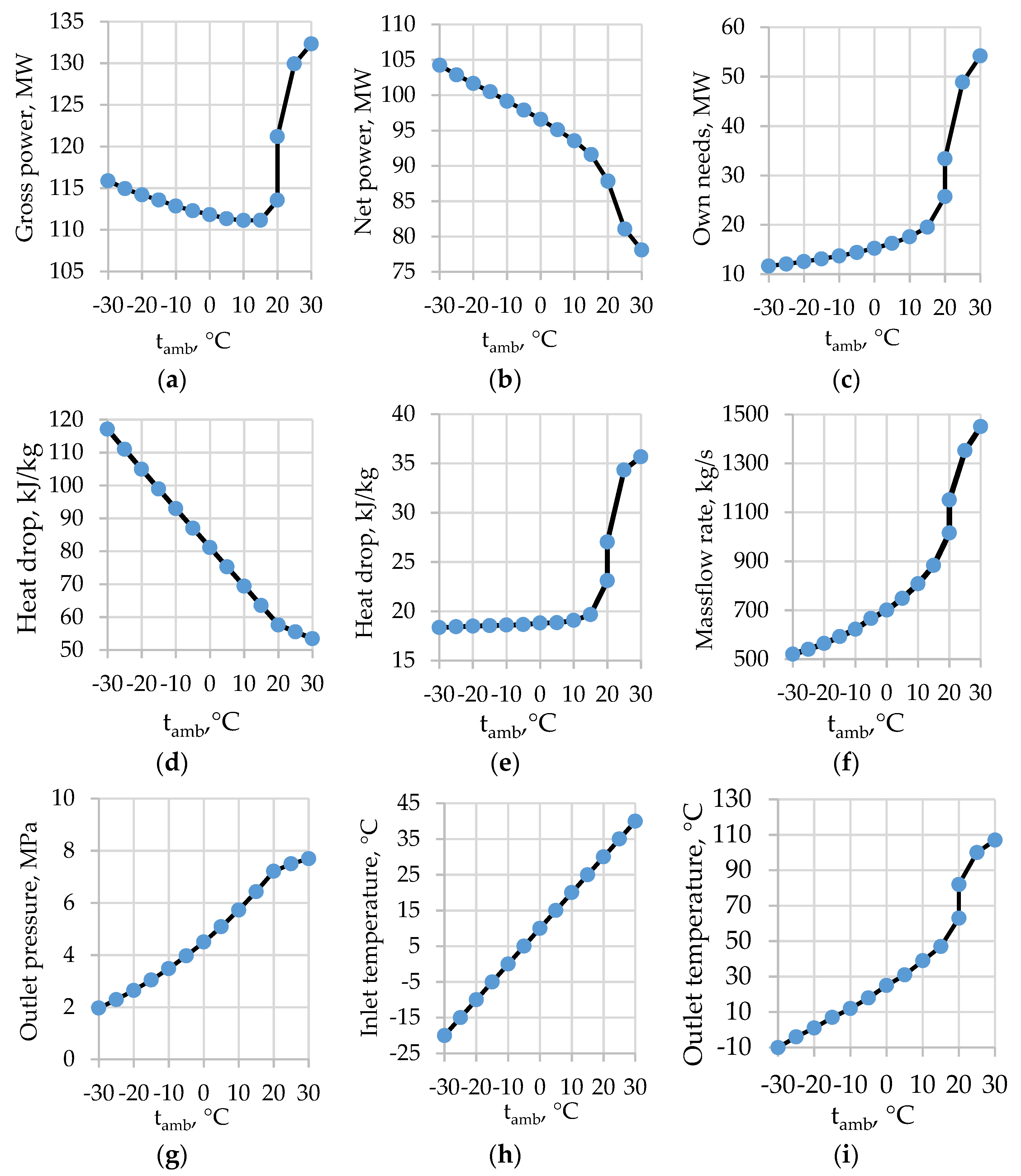
Figure 41. Ambient temperature influence on the performance of modified TPPs with BPSTs (Case 2b): (a) gross power, (b) net power, (c) own needs, (d) CO2 turbine heat drop, (e) CO2 pump/compressor heat drop, (f) mass flow rate, (g) CO2 turbine outlet pressure, (h) CO2 pump/compressor inlet temperature, and (i) CO2 pump/compressor outlet temperature.
-
An increase in the gross power of 7.6 MW (6.7% increment) due to the 13.3% higher carbon dioxide turbine mass flow;
- 2 turbine heat drop of 4.57% and mean increase in mass flow rate of 6.98%;
-
Mean increase in the gross power by 3.7 MW (3.1% increment) due to mean reduction in CO2 turbine heat drop of 2.4% and mean increase in mass flow rate of 8.7%;A domestic power consumption increase of 7.6 MW (29.3% increment) due to the 13.3% higher carbon dioxide mass flow rate and the 17.0% higher compression heat drop (this remarkable change of compression heat drop was related to the transition to gaseous fluid compression);
-
Mean increase in the domestic power consumption of 0.79 MW (6.78% increment) due to mean increase in mass flow rate of 6.98% and mean increase in CO2 pump heat drop of 0.71%;A constant net power output (0% increment was caused by the equality of the CO2 turbine and compressor power increments).
-
Mean reduction in the gross power of 0.47 MW (0.41% decrement) due to mean reduction in CO
-
Mean increase in the domestic power consumption of 6.94 MW (20.8% increment) due to mean increase in mass flow rate of 8.7% and mean increase in CO2 compressor heat drop of 10.65%;
-
Mean reduction in the net power of 1.26 MW (1.21% decrement).
- Reduction in the net power of 3.24 MW (3.7% decrement).
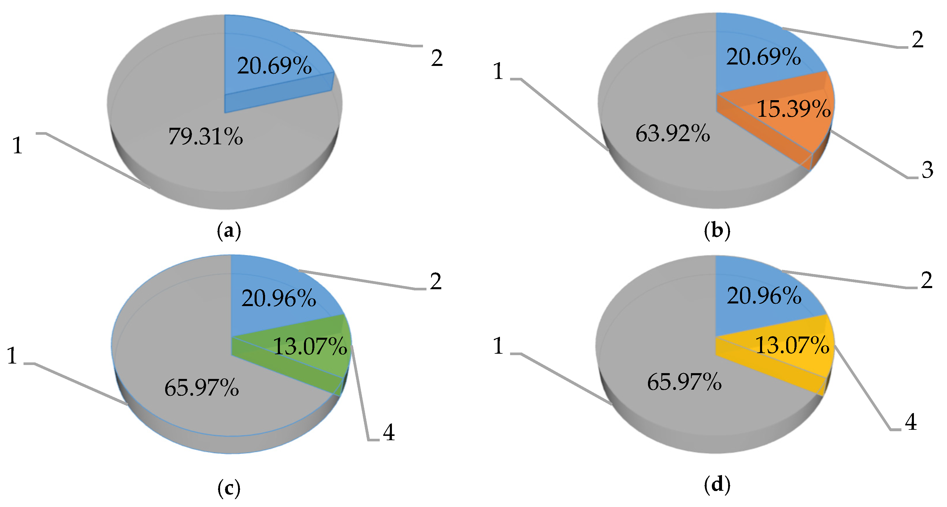
Figure 52. The heat of fuel combustion structure for the different TPPs with BPSTs producing electricity (without heat load) at the ambient temperature of 20 °C. 1—the net power of BPST power unit; 2—the heat losses in the cold source; 3—the net power of LPT power unit; 4—the net power of CO2 power unit. (a) Case 1, (b) Case 2a, (c) Case 2b (with CO2 condensation), and (d) Case 2b (without CO2 condensation).
- -
-
By 74% (Case 2a: increase from 20.69 to 36.08%);
- -
-
By 65% (Case 2b (with CO2 condensation): increase from 20.69 to 34.03%);
- -
-
By 56% (Case 2b (without CO2 condensation): increase from 20.69 to 34.03%).Table 81 summarizes the assessments of two versions of the modernization effect in prospective BPSTs.
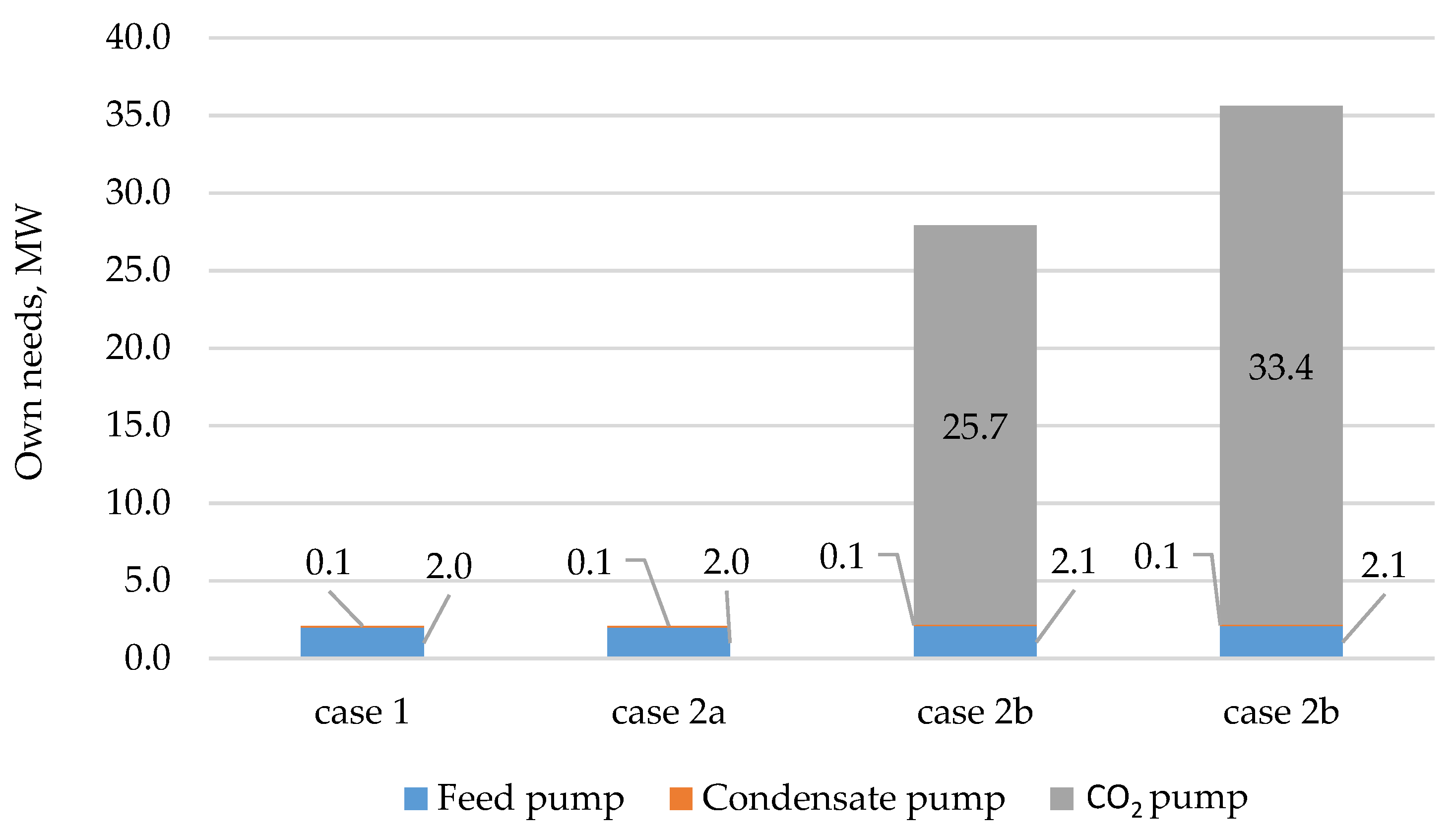 Figure 63. Own needs structure for the different TPPs with BPSTs producing electricity (without heat load) at the ambient temperature of 20 °C.Thus, the thermodynamic studies showed that BPST modernization using the superstructure of a carbon dioxide cycle is thermodynamically reasonable at an ambient temperature below 7 °C (Figure 74).Table 81.The comparison of the energy effect for modifications of TPPs with BPSTs.
№ TPP Name Average Annual Temperature, °C Net Power Increment for Case 2a, MW Net Power Increment for Case 2b, MW The Choice of Superstructure Case 1 Balakovskaya CHP 7.1 94.26 94.11 2a 2 Novocheboksarskaya CHP-3 3.5 69.26 70.55 2b 3 Kazanskaya CHP-2 4.0 69.26 70.40 2b 4 Nizhegorodskaya TPP 5.9 76.26 76.80 2b 5 Saratovskaya CHP-2 7.1 94.26 94.11 2a 6 Sterlitamakskaya CHP 4.9 94.26 95.30 2b 7 Irkutskaya CHP-9 2.2 94.26 95.59 2b 8 Kemerovskaya TPP 1.5 79.26 81.15 2b 9 Novo-Kemerovskaya CHP 1.5 94.26 96.15 2b The prospective power plant location scheme with the recommended modernization type is shown in Figure 85. The dark blue color shows the TPPs for Case 2a modernization; the red color shows Case 2b TPPs.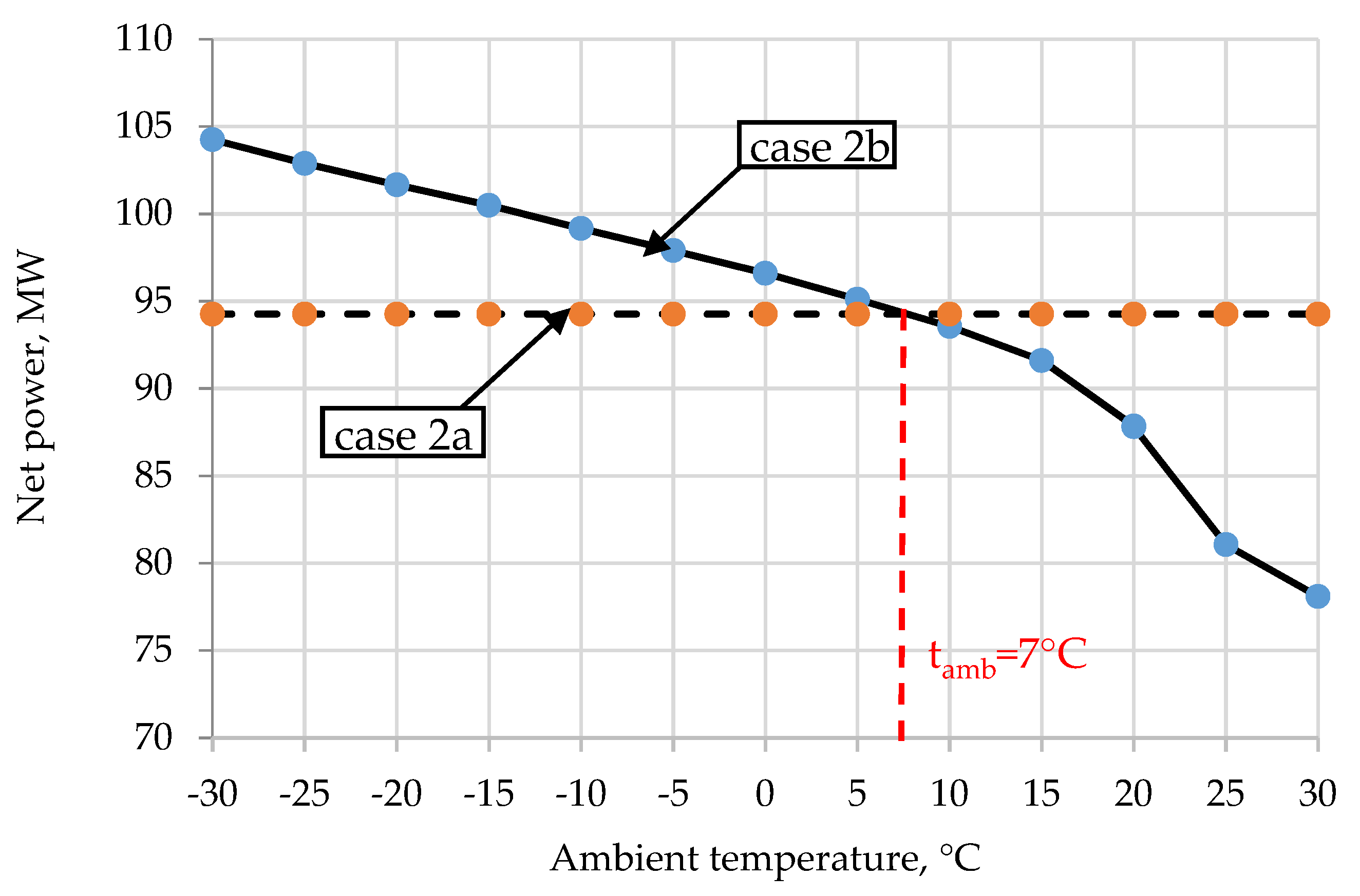 Figure 74.Diagram for the choice of TPPs with BPSTs modification type.Thus, the modernization method for a BPST by the superstructure of a carbon dioxide power cycle proposed in this work is advisable to use for seven of nine underloaded TPPs. The total increase in the net power for this case is 585.9 MW. In turn, the LPT superstructure is expedient for two of nine TPPs: the total increase in the net power, in this case, is 188.5 MW. It is important to note that the implementation of the described modernization methods will provide not only a significant increase in TPP energy efficiency but also contribute to the average reduction in specific CO2 emissions. This effect is since the additional power is produced at the expense of the utilization of useless low-potential heat without an increase in fuel consumption. An alternative way to upgrade the energy sector is the creation of oxy-fuel combustion power cycles [31,32,33][20][21][22]. The net efficiency of such power units can exceed 50% with an almost complete absence of emissions of harmful substances into the atmosphere. However, unlike the closed supercritical CO2 Brayton cycles, the semi-closed cycles with oxy-fuel combustion are still at the stage of experimental research. Therefore, the TPPs’ modification cases described here should be considered as one of the priority directions for increasing energy efficiency and environmental safety of electricity production in Russia.
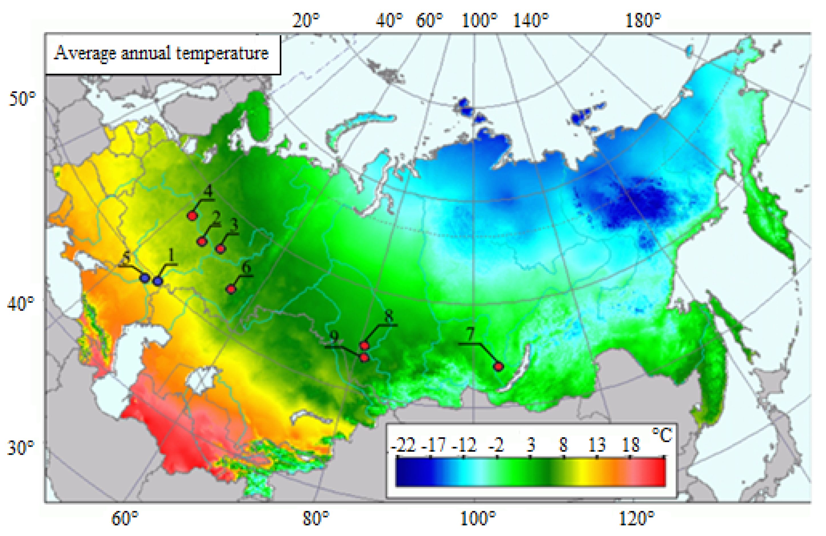 Figure 85.The location scheme for the modified TPPs with BPSTs in Russia. Blue point—for case 2a; red point—for case 2b.
References
- Ma, G.; Zhang, Y.; Yue, M.; Shi, Y. Thermal economy study on the waste heat utilization of a double reheat unit under coupled steam turbine and boiler. Appl. Therm. Eng. 2020, 175, 115112.
- Thanganadar, D.; Asfand, F.; Patchigolla, K.; Turner, P. Techno-economic analysis of supercritical carbon dioxide cycle integrated with coal-fired power plant. Energy Convers. Manag. 2021, 242, 114294.
- Morimoro, W. Validation Results of 1650 C Class JAC Gas Turbine at T-point 2 Demonstration Plant. Mitsubishi Heavy Ind. Tech. Rev. 2021, 58, 1.
- Okajima, Y.; Torigoe, T.; Mega, M.; Kuwabara, M.; Okaya, N. Development of Advanced TBC for 1650 °C Class Gas Turbine. In ITSC2021; ASM International: Almere, The Netherlands, 2021; pp. 695–699.
- Ol’khovskii, G.G. The Most Powerful Power-Generating GTUs (a Review). Therm. Eng. 2021, 68, 490–495.
- Salwan, G.K.; Subbarao, R.; Mondal, S. Comparison and selection of suitable materials applicable for gas turbine blades. Mater. Today Proc. 2021, 46, 8864–8870.
- Nourin, F.N.; Amano, R.S. Review of Gas Turbine Internal Cooling Improvement Technology. J. Energy Resour. Technol. 2021, 143, 080801.
- Lytvynenko, O.; Tarasov, O.; Mykhailova, I.; Avdieieva, O. Possibility of using liquid-metals for gas turbine cooling system. In Design, Simulation, Manufacturing: The Innovation Exchange; Springer: Cham, Switzerland, 2020; pp. 312–321.
- Bozhko, V.V. Modernization of the type “P” turbines aimed at their transition to the heat supply schedule. Exp. Oper. Modif. Turbines. Available online: http://www.combienergy.ru/stat/908-Modernizaciya-turboustanovok-tipa-Rs-celyu-ih-perevoda (accessed on 12 June 2021).
- Gribkov, A.M. Version of the CHP turbine axial location with the power generator placed on the HPT side. Therm. Power Ind. 2013, 3, 69.
- Ryzhenkov, V.A. Efficient protection against atmospheric corrosion of power production equipment during the repair and long-term standby periods. Reliab. Saf. Power Ind. 2017, 1, 43–46.
- Khlebalin Yu, M. Modernization of TPP with back-pressure turbine and intermediate superheating. Power Prod. Ind. 2005, 8, 2–4.
- Gafurov, A.M. Recovery of the low potential exhaust heat for the TPP efficiency increase during winter periods. Tatarstan Power Ind. 2014, 3–4, 69–76.
- Galashov, N.N.; Tsibulsky, S.А. Analysis of the efficiency of a triple combined cycle gas turbine. Bulletin of the Tomsk Polytechnic University. Georesour. Eng. 2014, 4, 33–38.
- Song, J.; Li, X.; Ren, X.; Gu, C. Performance analysis and parametric optimization of supercritical carbon dioxide (S-CO2) cycle with bottoming Organic Rankine Cycle (ORC). Energy 2018, 143, 406–416.
- Grinman, M.I.; Fomin, V.A. Application prospects of power production facilities on low boiling heat carrier. Compress. Equip. Pneum. 2009, 7, 35–39.
- Melnikov, A.S.; Popov, B.I. Determination of the efficiency of condensing and heating turbine units based on the energy characteristics of turbines. Proc. Natl. Acad. Sci. Belarus A Ser. Phys. Tech. Sci. 2020, 64, 438–446. Available online: http://vestift.belnauka.by/jour/issue/view/33 (accessed on 24 June 2021).
- Kawagishi, H.; Onoda, A.; Shibukawa, N.; Niizeki, Y. Development of moisture loss models in steam turbines. Heat Transf.—Asian Res. 2013, 42, 651–664.
- Sengupta, B.; Bhattacharya, C. Investigation of energy loss on fractional deposition in last stages of condensing steam turbine due to blade shape and moisture droplet size. J. Eng. Gas Turbines Power 2018, 140, 072601.
- Imteyaz, B.; Tahir, F.; Habib, M.A. Thermodynamic assessment of membrane-assisted premixed and non-premixed oxy-fuel combustion power cycles. J. Energy Resour. Technol. 2021, 143, 052303.
- Wei, X.; Manovic, V.; Hanak, D.P. Techno-economic assessment of coal-or biomass-fired oxy-combustion power plants with supercritical carbon dioxide cycle. Energy Convers. Manag. 2020, 221, 113143.
- Wimmer, K.; Sanz, W. Optimization and comparison of the two promising oxy-combustion cycles NET Power cycle and Graz Cycle. Int. J. Greenh. Gas Control 2020, 99, 103055.
More