Factors Affecting FIV in Internal Two-Phase Flow: Comparison
Please note this is a comparison between Version 3 by Conner Chen and Version 8 by Conner Chen.

Two-phase flow is commonly encountered in various engineering systems. Momentum fluctuation in two-phase flow can create undesirable and destructive vibrations. These vibrations have attracted considerable attention and are known as flow-induced vibrations (FIV). Different factors effecting FIV is two phase flow is discussed here in detail.

  • flow-induced vibrations
  • dimensionless forces
  • dominant frequency
  • multiphae flow

1. Effect of Flow Velocity

The effect of flow velocity on FIV was reported in research conducted on multiphase FIV at bends with 20.6 mm internal diameter [1][2]. A piezoelectric force sensor was used to record excitation force signal and an optical probe was used to record void fraction data. It was reported that the amplitude and predominant frequency of excitation forces increase linearly with flow velocity, for a given void fraction. As the velocity of the fluid increases, the higher modes become excited. Moreover, the authors correlated the root mean square of excitation force (FRMS) with inlet superficial mixture velocity (Vm). The experimental results on U-bends suggested that the relationship between excitation forces and superficial velocities can be expressed in equation below, as shown below: 
F R M S V m 1.2
The same trend was also reported by Giraudeau et al. [3]. The authors conducted experiments to investigate FIV for various diameters of U-bends, for a vertically upward two-phase flow. The experiments were conducted for volumetric quality or gas void fraction, β, of 25%, 50%, 75%, and 95%, and superficial mixture velocity between 1–12, 2–14, 2–20, and 5–30 m/s, respectively. These conditions represent bubbly, churn, slug, and annular flow regimes. It was concluded that for a specific value of void fraction, excitation forces on bends increase with an increase in the mixture velocity. This was true for the volumetric quality values of 50%, 75%, and 95%. However, in the case of 25% void fraction, there is a large decrease in forces between 2 and 3 m/s mixture velocity. This is attributed to the fact that in this range, a transition from slug/bubbly flow to finely dispersed bubbly flow occurs. Force spectrum data demonstrated that the peak/dominant frequency shows a linear increasing trend with superficial velocity for all the observed conditions.
Hossain et al. [4] reported the effect of superficial velocities on excitation forces and dominant frequency for an upward two-phase flow in a vertical 90° elbow of internal diameter 0.0525 m (2 inch) and curvature radius of 0.0762 m (3 inch), specifically for slug and churn flows. To study the effect of superficial liquid velocity (Vsl), it was varied from 0.642 to 5 m/s, while maintaining a constant superficial gas velocity (Vsg) at 5 m/s. Furthermore, to study the effect of superficial gas velocity, it was varied from 0.5 to 9.04 m/s, while maintaining a constant superficial gas velocity at 0.642 m/s. It was observed that the magnitude of excitation force increases and the predominant frequency decreases with the increasing gas superficial velocity, while both frequency and force magnitude increase with the increasing liquid superficial velocity.
The effect of superficial velocity on force fluctuations and peak frequency was studied by Liu et al. [5], for vertically upward two-phase flow in 52.6 mm (2 inch) internal diameter pipe with a bend having a radius of 76.2 mm (3 inch). The ranges for liquid and gas phase superficial velocities investigated are 0.61–2.31 m/s and 0.1–18 m/s, respectively, covering slug, churn, annular, and bubbly flow regimes. For a fixed liquid superficial velocity, the RMS force increases monotonically with an increase in superficial velocity of gas. Moreover, the RMS force increases with liquid flow rates, but with a few exceptions, which can be attributed to flow regime transition. In the case of predominant frequency, for a constant liquid phase flow rate, the peak frequency increased to its maximum value when flow transitioned from bubbly to slug flow. A further increase in flow rate of gas phase, caused the peak frequency to decrease first for slug and churn flow regimes and increase again for annular flow regime. For a fixed flow rate of gaseous phase, the peak/dominant frequency increased with the liquid phase flow rate in general.
Experimental and numerical techniques were used by Wang et al. [6] to investigate the dynamic response of a horizontal pipe under slug flow. It was reported that these dynamic responses are created as a combined effect of the interaction between fluid and structure, and flow characteristics. The velocity of slug body has a considerable effect on the response of vibrations since this velocity affects centrifugal and Coriolis forces. The effect of slug transitional velocity was found to be intense, considering that it affects the rate of change of system properties, such as damping, stiffness, and loading.
Wang et al. [7] applied the one-way fluid structure interaction model to study the interaction of multiphase flow in a 90° pipe bend using numerical simulation. The geometry and flow parameters used were similar to Liu et al. [5]. The two-phase flow was simulated using the volume of fluid (VOF) model and realizable k-є turbulence model. It was reported that at fixed liquid superficial velocity, the increasing gas velocity increases the maximum total deformation and equivalent stress, while the decreasing trend was observed with the increasing superficial liquid velocity, while maintaining a constant gas superficial velocity. The evolution of slug flow affected the position of distribution of maximum stress and deformation. The maximum value of total deformation was found at the 90° pipe bend for low liquid superficial velocities, but as the superficial velocity of liquid phase increases, the location of maximum value of total deformation was in the horizontal section of pipe. As a result, serious cyclic impact on the 90° pipe bend will be produced for higher superficial gas velocity.
In summary, fluctuation forces increase with the increase in gas superficial velocity while maintaining a constant liquid superficial velocity. Moreover, this condition is true if pweople reverse the conditions, where liquid superficial velocity increases while maintaining a constant gas superficial velocity. A few exceptions exist as reported, which are primarily due to flow regime transition. The peak/dominant frequency of fluctuations increases with liquid superficial velocity, but shows inconsistent behavior with the increasing gas superficial velocity, depending on flow regime change.

2. Effect of Pipe Geometry and Sizes

The flow behaviors in small diameter pipe bends and large diameter pipe bends are different. Schlegel et al. [8] reported that pipes can be characterized as small or large based on non-dimensional hydraulic diameter, DH, as shown in Equation below. Small pipes have DH less than 18.6 and larger pipes have DH greater than 40. With relevance to air-water two-phase flow, diameters < 0.0507 m correspond to DH = 16.8, while diameters >0.1091 m represent DH = 40. The region between these two extremes is known as the transition region and affects both large and small diameter pipes, as observed. Mishima and Ishii [9] and Schlegel et al. [8] reported that bubbly flow regime is present in small as well as large diameter pipes. Beyond the bubbly flow regime, as the superficial velocities increase, gas bubbles with larger dimensions begin to form in both small and larger diameter pipes. In small pipes, these bubbles grow and fill the entire pipe, creating long slugs, which are known as slug flow regime. In large pipes, these bubbles form cap bubbles, which are known as cap bubbly flow regime. By further increasing the velocity, the flow in smaller pipes remains as a stable slug flow, while a churn turbulent flow regime develops in pipes with a larger diameter.
D H * = D H σ g Δ ρ

where
where 
DH
g
σ
, and 
Δρ, are hydraulic diameter, gravitational acceleration, liquid phase surface tension, and difference of density between two phases, respectively.
, are hydraulic diameter, gravitational acceleration, liquid phase surface tension, and difference of density between two phases, respectively. Yih and Griffith [10] investigated three different pipe diameters (6.35, 15.9, 25.4 mm) and reported that unsteady momentum fluxes decrease as the pipe diameter increases. This is primarily due to the fact that phases are mixed better in large pipes when compared to small pipes. Overall, the pipe diameter has a very little effect on predominant frequency. The authors also reported that high transverse vibrations were observed in rectangular pipes, which were not observed in round pipes. These transverse vibrations can be attributed to the fact that rectangular pipes have low natural frequency. Giraudeau et al. [3] investigated the effect of four different diameters (12, 15, 20, 52 mm) of U-bends on FIV for a vertically upward two-phase flow. For all conditions tested, the RMS force increased with the tube internal diameter. The increasing trend in RMS force was D1.38, D1.52, and D1.9 on average for 50%, 75%, and 95% void fraction, respectively. It was reported that the peak/main frequency on force spectrum generally decreases with the tube diameter. Chinenye-Kanu et al. [11] reported a variation in the fluctuating forces with diameter. A validated numerical modelling approach, which was used for 52.5 mm (2 inch) internal diameter pipe geometry by Hossain et al. [4] was applied to a 203.2 mm (8 inch) internal diameter pipe geometry. It was reported that peak frequencies for gas superficial velocities between 0.773 and 9.04 m/s were higher in pipes with smaller diameter compared to larger diameter pipes for similar flow conditions. Peak frequency was higher in churn flow regime for the large internal diameter pipe and in slug flow regime for the small pipes. Therefore, slug flow is critical for multiphase fluid-induced vibrations in small diameter pipes and churn flow is important when large diameter pipes are involved. The fluctuation force displayed a similar behavior in both pipe sizes by increasing monotonically with gas superficial velocity. Moreover, the study showed that for large to small pipe diameter ratio of 4, fluctuation forces were about 10× higher in the large dimeter pipe when compared to the small diameter pipe. Later, Asiegbu et al. [12] extended this study to investigate different diameter pipes (0.0525, 0.1016, 0.2032 mm). It was reported that at a constant liquid phase superficial velocity, the predominant frequency of force fluctuations increases with the increase in gas superficial velocity within the slug flow regime and drops when the flow regime transitioned into churn flow for 0.0525 mm (2 inch) and 0.2032 mm (8 inch) diameter pipe. For the case of 0.1016 mm (4 inch), the behavior of the pipe was more irregular. It was also reported that the presence of internal two-phase flow changes the natural frequency of all pipes, but the effect was more dominant in small diameter pipes when compared to large pipes. Belfroid et al. [13] conducted experimentations to investigate the effects of FIV in large diameter pipes (i.e., 6 inch). Two different bend configurations were used with a radius of 1.5 D, one elbow and another consisted of an elbow with a U-bend upstream. The results obtained were reported to be higher than smaller diameter pipes, but were comparable with large diameter pipes (70 and 100 mm) [14][15]. A correlation to determine forces was introduced using the quasi-steady approach, as shown in equation below. A constant, C, of 25 and 10 is recommended to determine FRMS for large and small pipes, respectively, as follows: F R M S = C ρ l V m 2 A W e 0.4
where ρl is the liquid phase density, Vm is the mixture velocity, A is the cross-sectional area of pipe, C is a constant, and We is the Weber number.
Riverin and Pettigrew [2] performed experiments on bends with different radii of curvature, R/D, (0.5, 2, 5, 7.2) and reported that R/D of the bend has a minimal effect on excitation forces. A similar conclusion regarding the minimal effect of bend radius was derived by Belfroid et al. [16]. Moreover, Cargnelutti et al. [17][18] reported the effect of radius of curvature on excitation forces. In their experiments, it was found that a larger bend radius showed greater forces when compared to a smaller bend radius. This increase in forces was attributed to the larger pressure drop in the bend with larger radius of curvature, which causes larger excitations due to the larger pressure difference. Kim et al. [19] reported that the bend radius has a direct effect on the distribution and development of local parameters. Moreover, it changes the void fraction and effects phase separation at the elbow. Yamano et al. [20][21] investigated the effect of two different radii of curvature (1 and 1.5) on FIV and reported that flow separation is continuous in short elbow and intermittent in larger elbow at the exit. Moreover, the authors observed the secondary flow behavior at the elbow, which showed that the position of high-turbulence intensity region and separation region was affected by the radius of curvature. In summary, the excitation forces increase with the increasing diameter, while the dominant frequency decreases with the increasing diameter. The majority of these findings are based on small diameter pipes. According to Schlegel et al. [8], flow behavior in small and large pipe diameters is different. Therefore, it would be inappropriate to derive conclusions regarding FIV behavior in large pipes based on conclusions derived for small pipes and vice versa. This is also true when comparing horizontal and vertical two-phase flows. The database available on large diameter pipes is almost non-existent and further studies on their behavior are needed since the majority of practical industrial pipes are with larger diameters. In addition, it is noted that the literature on the effect of bend radius is not explored properly, and very limited variations and cases are studied. Riverin and Pettigrew [2] only studied four different bend radii and other research involved studied two different radii [17][20][21]. Therefore, there is a big gap in the body of knowledge. A further exploration on different bend radii is highly recommended, considering the dimension of bend radius effect parameters, such as void fraction, pressure drop, and phase separation. These parameters can lead to different behaviors of excitation forces and vibrations.

3. Effect of Flow Regimes

Two-phase flow can be divided into different flow regimes depending on their properties and appearances. Various flow regime maps are introduced over time to identify flow regimes using visual inspection and flow rates of phases involved [22][23]. Kaichiro and Ishii [9] used void fraction to identify criteria for different flow regimes and established a flow regime map with gas superficial velocity and liquid superficial velocity as horizonal and vertical coordinates. This criterion was developed for vertical two-phase flow and their results are comparable with the existing literature. More advanced methods, such as the measurement of void fraction using X-rays [24], electrical capacitance tomography [25], rotating electric field conductance gauge [26], conductivity and electrical impedance [27] are also being used to identify different flow regimes. Different flow regime visualizations are shown in Figure 14 to help in understanding and better visualizing the different types of flow regimes.
                                                                                Figure 1. Flow visualization. (
a
) Flow patterns in horizontal pipe, (
b
) flow patterns in vertical pipe.
Flow regime is a critical parameter when discussing FIV in two-phase flow and different flow regimes cause different magnitudes of vibrations. Cargnelutti et al. [17][18] investigated the effect of two-phase flow on FIV in a 6-mm pipe with bend in different configurations. It was reported that slug flow showed the highest absolute forces followed by annular flow, while stratified flow showed the lowest forces. These observations were also verified in another research [16]. Cargnelutti et al. [17] developed a simple slug unit model by considering momentum fluctuation and neglecting turbulence and friction effects. This model could explain the forces generated by slug flow, but it was unable to describe forces due to annular and stratified flow regimes since no distinct slugs travel through the pipe in these flow regimes. Instead, a mixture model was presented to estimate excitation forces due to annular and stratified flows. This model is analogous to single-phase conditions, where a simple mixture momentum is considered. The results of these models were comparable to experimental results, but the accuracy can be further increased by considering parameters, such as random excitations due to turbulence, friction, gravity, and impact force. Liu et al. [5] conducted experiments on vertically upward two-phase flow in 52.6 mm (2 inch) internal diameter pipe with a bend radius of curvature of 76.2 mm (3 inch). In theirs study, 36 multiphase flow cases, which include bubbly, slug, churn, and annular flow regimes, were studied. The investigated superficial velocities range of gas and liquid are 0.61–2.31 m/s and 0.1–18 m/s, respectively. For all the flow regimes, the high frequency component (>20 Hz) measured by the force sensor was insignificant. RMS values of force fluctuations were recorded in x and z directions and their peak frequency was plotted. The RMS of force fluctuation in x and z directions are the lowest for bubbly flow regime and the value increases as the flow enters slug and churn flow regimes. In addition, it reaches the maximum value after the flow transitions into an annular flow. On the other hand, the peak frequency of force fluctuation is almost zero in bubbly flow, except for the 7-Hz peak at liquid superficial velocity of 1.78 m/s and air superficial velocity of 0.407 m/s. This random peak did not show a significant amplitude and was due to the absence of system fluctuations. When the flow transitioned into slug and churn flows, the peak frequency increased instantly to its overall maximum value due to the formation of slug bubbles in vertical section, and then decreased a little before transitioning into annular flow. The peak frequency increased again in annular flow, which was due to the disturbance wave effect. Overall, slug and churn flow regimes showed the highest peak frequencies in the range of 8 to 10 Hz. Riverin and Pettigrew [2] also reported the behavior of force transducer signals at the elbow due to different flow regimes. Force signals are composed of regular impulses in slug flow regime, which can be attributed to the passage of liquid slugs. The force spectrum in bubbly flow regime is rather broadband due to the presence of bubbles, whereas a mixture of narrow-band and periodic components was detected in churn flow. The force signal observed in annular flow was composed of sharp impulses, which can be due to droplet entrainment. Although the majority of the literature primarily focuses on how FIV is affected by different flow regimes, it is also reported that vibration can cause a change in flow regime. Enoki et al. [28][29] observed the effect of oscillation on horizontal two-phase flow patterns in rectangular mini-channel. The flow behavior became increasingly disturbed under the influence of mechanical oscillations when compared to a stationary condition. The oscillation effect of the two-phase flow behavior was herein confirmed [29]. Moreover, it was reported than when the test section oscillated above a certain level, stratified flow would change into annular flow [29]. In conclusion, FIV behavior changes with a change in flow regime and it is a flow regime specific phenomenon. Flow-induced vibrations in slug and churn flow regimes are more intense and a further investigation is necessary, especially in annular flow regime, which appears to have received the least attention by researchers. In addition, FIV research relies on flow regime maps developed in 1970s and 1980s [23][30], and new approaches, such as flow regime map developed using machine learning algorithms or flow regimes maps for specific experimental conditions, are encouraged to be used.

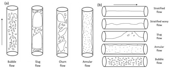
4. Effect of Void Fraction

Void fraction or liquid holdup is a dimensionless parameter and can be defined as the ratio of cross-sectional area of pipe  occupied by vapor phase or gas to the total cross-sectional area.

Riverin and Pettigrew [31][63] concluded from their experiments on multiphase flow in U-bend that excitation forces are indeed affected by the change in void fraction. In theirs study, the effect of excitation forces on bends at values of 25%, 50%, 75%, and 95% gas void fraction were studied. The authors reported that for a specific velocity, the excitation forces increase as void fraction increases. Maximum forces are reported between 50% to 60% gas void fraction. Beyond 60% gas void fraction, the excitation forces start to decrease. However, it is noteworthy that this effect is normally due to flow regime change. For void fractions between 50% and 60%, flow regime is normally associated with slug or churn flow, which possesses the maximum momentum flux. In addition, they are more prominent when it comes to excitation forces when compared to bubbly (25%) and annular (95%) flows.

Giraudeau et al. [32][64] conducted experiments to investigate flow-induced vibrations in 52 mm (2 inch) internal diameter U-bend, with a vertically upward two-phase flow. The range of gas void fraction tested during experiments are 25%, 50%, 75%, and 95%. From the force spectra data, it was concluded that the average void fraction signal corresponds to force spectra. It was reported that for a constant velocity, the excitation forces increase with void fraction until 75%, and then decrease with further increase in velocity. This behavior agrees with previous observations [31][63]. For 25% void fraction, forces start to increase after 3 m/s in bubbly flow. These forces are produced due to propagation of void fraction waves [33][34][93,94]. For 50% void fraction, the force increases with velocity until 7 m/s and after further increase in velocity, the forces do not show any increase, which can be explained by the transition of flow regime from unstable slug flow to bubbly flow regime. The same increasing behavior can be obtained for void fraction of 75% until velocity is increased to 14 m/s and after further increase in velocity, the force decreases. This was due to the transition of flow from unstable slug to churn flow regime. In 95% void fraction, the transition from churn to annular flow is observed at 20 m/s. Forces increase first and then start to decrease after 20 m/s due to less momentum variation in annular flow and void fraction when compared to slug and churn flow regimes.

Liu et al. [35][66] reported that void fraction fluctuations show a similar trend as force fluctuations, and thus it is important to determine the changes in void fraction when the two-phase flow passes through the pipe bend. Moreover, the authors observed the predominant frequency of void fraction fluctuation signals and found that for a fixed liquid superficial velocity, as superficial velocity of gas is increased from bubbly to slug flow, the predominant frequency of void fraction fluctuations reaches a maximum value, upon further increase the predominant frequency decreases in churn flow followed by an increase again in annular flow. Wang et al. [36][59] reported that when slug flow passes through a 90° bend, the flow regime transition affects the increase or decrease in void fraction after passing through the pipe bend. For slug flow, at a constant gas superficial velocity, void fraction decreases with the increasing liquid velocity after the slug passes through the pipe bend. However, an increasing gas superficial velocity has a minimal effect on this phenomenon. A relationship between void fraction, liquid and gas flow rates and flow regimes based on data available in the literature [37][95] has been developed as illustrated in Figure 25. Notably, these data are for upward vertical flow, a flow type widely used in the study of FIV. This figure concludes the effect of void fraction on excitation forces and its relation to flow regime. For a fixed mixture velocity, the excitation forces increase as gas void fraction increases, where the maximum forces were reported to be between 50% and 75% void fraction value, and upon further increase, the excitation forces start to decrease, as shown in Figure 25. In addition, Figure 2 5 shows that this range covers the slug/churn flow regime, which shows maximum momentum fluctuation and, in turn, produces the highest forces. The annular and bubbly flows occur outside this range of void fraction, which shows lesser forces due to the less turbulent nature. This change is attributed to the change in flow regime as thwe increased the void fraction, rather than the effect of void fraction.

Relationship between void fraction with liquid and gas flowrates, and flow regimes and excitation forces.

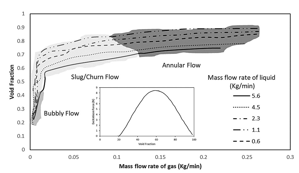
Figure 25. Relationship between void fraction with liquid and gas flowrates, and flow regimes and excitation forces.

5. Comparison of Dimensionless Forces

The dashed line shown in Figure 3Figure below is drawn using Riverin equation with C value of 10. This was proposed as a reasonable approximation of dimensionless forces. The dash dotted line shown in Figure  is drawn using C of 3.5 and it is the best fit curve for slug flow regime. Giraudeau et al. proposed that to be conservative, an upper bound of dimensionless forces should be defined and from their experiments on 12 to 52 mm internal diameter U-bends, Cmax of 25 was proposed. This corresponds to the dotted line shown in Figure 3Figure . The experimental results for 12 and 52 mm U-bends are included here, which shows that Cmax = 25 is a good approximation for upper limit. The dimensionless forces due to slug flow from experiments conducted by Cargnelutti et al., in 6 mm internal diameter horizontal and vertical elbows for bend radii of 16.5 and 25 and the results for 25.4 mm (1 inch) internal diameter elbow, are also recorded in Figure 3Figure. Notably, both horizontal and vertical elbows are subjected to the horizontal two-phase flow in these experiments. The overall forces on vertical elbow are higher than the horizontal elbow, which was thought to be due to gravity. Notably, forces in vertical elbow are also higher than the maximum limit introduced by Giraudeau et al. at C of 25. The forces due to the 16.5 bend radius are lower than the 25 mm bend radius for the same diameter pipe, which shows that the bend radius affects the forces. Moreover, it can be observed that the forces in 25.4 mm (1 inch) pipe are higher than the 6 mm experiments. This behavior was unusual, considering that the 25.4 mm (1 inch) experiments contained more gas than the 6 mm experiments. Cargnelutti et al. reported that this can also be due to the difference of stiffness of material used (glass vs. perspex). Overall, the results of Cargnelutti experiments show higher forces than the Revirin experiments and results for 25.4 mm bend are higher than C = 10 line. Experimental results for 20 mm internal diameter tee [38][42], for elbow with 70 mm diameter under the horizontal flow [39][98], and for 6 to 25 mm diameter vertical U-tubes, are also reported. All these results are in agreement with Riverin et al. approximation at C of 10. Results for 52.5 mm vertical elbow are also presented and these results are spread over a wide range from C of 3.51 to 25 lines. This can be attributed to the fact that 0 to 100% void fraction was considered, covering a wide range of flow conditions. The simulation results of Hossain et al. for vertical elbow of 52.5 mm diameter are presented and they mostly lie between C of 10 and 25 lines. Figure 3Figure below can serve as a database for comparison and can also be used to validate the simulation results.

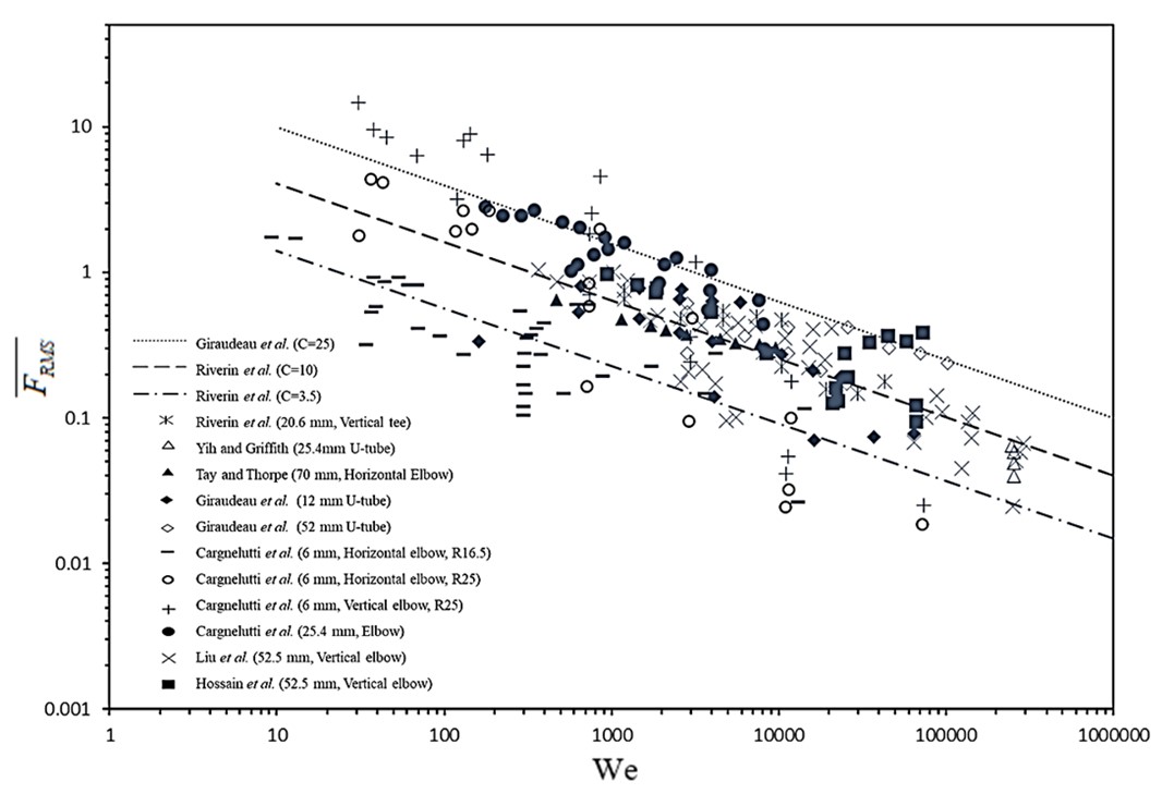
                                                                                  Figure 3.: Comparison of dimensionless forces plotted against the Weber

Comparison of dimensionless forces plotted against the Weber number 

number 

References

  1. Riverin, J.L.; Pettigrew, M.J. Vibration Excitation Forces Due to Two-Phase Flow in Piping Elements. J. Press. Vessel Technol. Trans. ASME 2007, 129, 7–13. Riverin, J.L.; de Langre, E.; Pettigrew, M.J. Fluctuating Forces Caused by Internal Two-Phase Flow on Bends and Tees. J. Sound Vib. 2006, 298, 1088–1098.
  2. Giraudeau, M.; Mureithi, N.W.; Pettigrew, M.J. Two-Phase Flow-Induced Forces on Piping in Vertical Upward Flow: Excitation Mechanisms and Correlation Models. J. Press. Vessel Technol. Trans. ASME 2013, 135, 1–16. Riverin, J.L.; Pettigrew, M.J. Vibration Excitation Forces Due to Two-Phase Flow in Piping Elements. J. Press. Vessel Technol. Trans. ASME 2007, 129, 7–13.
  3. Park, J.W.; Drew, D.A.; Lahey, R.T. The Measurement of Void Waves in Bubbly Two-Phase Flows. Nucl. Eng. Des. 1994, 149, 37–52. Giraudeau, M.; Mureithi, N.W.; Pettigrew, M.J. Two-Phase Flow-Induced Forces on Piping in Vertical Upward Flow: Excitation Mechanisms and Correlation Models. J. Press. Vessel Technol. Trans. ASME 2013, 135, 1–16.
  4. Sun, B.; Yan, D.; Zhang, Z. The Instability of Void Fraction Waves in Vertical Gas-Liquid Two-Phase Flow. CNSNS 1999, 4, 181–186. Hossain, M.; Chinenye-Kanu, N.M.; Droubi, G.M.; Islam, S.Z. Investigation of Slug-Churn Flow Induced Transient Excitation Forces at Pipe Bend. J. Fluids Struct. 2019, 91, 102733.
  5. Liu, Y.; Miwa, S.; Hibiki, T.; Ishii, M.; Morita, H.; Kondoh, Y.; Tanimoto, K. Experimental Study of Internal Two-Phase Flow Induced Fluctuating Force on a 90° Elbow. Chem. Eng. Sci. 2012, 76, 173–187.
  6. Wang, Z.; He, Y.P.; Li, M.Z.; Qiu, M.; Huang, C.; Liu, Y.D.; Wang, Z. Fluid—Structure Interaction of Two-Phase Flow Passing Through 90° Pipe Bend Under Slug Pattern Conditions. China Ocean Eng. 2021, 35, 914–923. Wang, L.; Yang, Y.; Li, Y.; Wang, Y. Dynamic Behaviours of Horizontal Gas-Liquid Pipes Subjected to Hydrodynamic Slug Flow: Modelling and Experiments. Int. J. Press. Vessel. Pip. 2018, 161, 50–57.
  7. Ghajar, A.J.; Bhagwat, S.M. Frontiers and Progress in Multiphase Flow I; Springer: Berlin/Heidelberg, Germany, 2014; ISBN 9783319043586. Wang, Z.; He, Y.P.; Li, M.Z.; Qiu, M.; Huang, C.; Liu, Y.D.; Wang, Z. Fluid—Structure Interaction of Two-Phase Flow Passing Through 90° Pipe Bend Under Slug Pattern Conditions. China Ocean Eng. 2021, 35, 914–923.
  8. Chen, W.; Ji, C.; Williams, J.; Xu, D.; Yang, L.; Cui, Y. Vortex-Induced Vibrations of Three Tandem Cylinders in Laminar Cross-Flow: Vibration Response and Galloping Mechanism. J. Fluids Struct. 2018, 78, 215–238. Schlegel, J.P.; Miwa, S.; Chen, S.; Hibiki, T.; Ishii, M. Experimental Study of Two-Phase Flow Structure in Large Diameter Pipes. Exp. Therm. Fluid Sci. 2012, 41, 12–22.
  9. Tay, B.L.; Thorpe, R.B. Hydrodynamic Forces Acting on Pipe Bends in Gas-Liquid Slug Flow. Chem. Eng. Res. Des. 2014, 92, 812–825. Kaichiro, M.; Ishii, M. Flow Regime Transition Criteria for Upward Two-Phase Flow in Vertical Tubes. Int. J. Heat Mass Transf. 1984, 27, 723–737.
  10. Yih, T.; Griffith, P. Unsteady Momentum Fluxes in Two-Phase Flow and the Vibration of Nuclear Reactor Components; Massachusetts Institute of Technology: Cambridge, MA, USA, 1968.
  11. Chinenye-Kanu, N.M.; Hossain, M.; Droubi, M.G.; Islam, S.Z. Numerical Investigation of Two-Phase Flow Induced Local Fluctuations and Interactions of Flow Properties through Elbow. Lect. Notes Mech. Eng. 2019, 2019, 124–141.
  12. Asiegbu, N.M.; Hossain, M.; Droubi, G.M.; Islam, S.Z. Investigation of the Effects of Pipe Diameter of Internal Multiphase Flow on Pipe Elbow Vibration and Resonance. Proc. Inst. Mech. Eng. Part E J. Process. Mech. Eng. 2022, 2022, 095440892211155.
  13. Belfroid, S.P.; Nennie, E.; Lewis, M. Multiphase Forces on Bends—Large Scale 6” Experiments. In Proceedings of the SPE Annual Technical Conference and Exhibition, Dubai, United Arab Emirates, 26–28 September 2016.
  14. Tay, B.L.; Thorpe, R.B. Effects of Liquid Physical Properties on the Forces Acting on a Pipe Bend in Gas-Liquid Slug Flow. Chem. Eng. Res. Des. 2004, 82, 344–356.
  15. Nennie, E.D.; Belfroid, S.P.C.; van Bokhorst, E.; Remans, D. Multiphase Fluid Structure Interaction in Pipe Systems with Multiple Bends. In Proceedings of the 10th International Conference on Flow-Induced Vibration, Dublin, Ireland, 3–6 July 2012; TNO Publications: The Hague, The Netherlands.
  16. Belfroid, S.P.C.; Cargnelutti, M.F.; Schiferli, W.; Van Osch, M. Forces on Bends and T-Joints Due to Multiphase Flow. Am. Soc. Mech. Eng. Fluids Eng. Div. FEDSM 2010, 3, 613–619.
  17. Cargnelutti, M.F.; Belfroid, S.P.C.; Schiferli, W.; Van Osch, M. Two-Phase Flow-Induced Forces on Bends in Small Scale Tubes. J. Press. Vessel. Technol. 2009, 132, 1–9.
  18. Cargnelutti, M.F.; Belfroid, S.P.C.; Schiferli, W.; Van Osch, M. Multiphase Fluid Structure Interaction in Bends and T-Joints. In Proceedings of the ASME 2010 Pressure Vessels and Piping Division/K-PVP Conference, Bellevue, DC, USA, 18–22 July 2016; pp. 1–8.
  19. Kim, S.; Park, J.H.; Kojasoy, G.; Kelly, J.M.; Marshall, S.O. Geometric Effects of 90-Degree Elbow in the Development of Interfacial Structures in Horizontal Bubbly Flow. Nucl. Eng. Des. 2007, 237, 2105–2113.
  20. Yamano, H.; Tanaka, M.; Murakami, T.; Iwamoto, Y.; Yuki, K.; Sago, H.; Hayakawa, S. Unsteady Elbow Pipe Flow to Develop a Flow-Induced Vibration Evaluation Methodology for Japan Sodium-Cooled Fast Reactor. J. Nucl. Sci. Technol. 2011, 48, 677–687.
  21. Yamano, H.; Tanaka, M.A.; Kimura, N.; Ohshima, H.; Kamide, H.; Watanabe, O. Development of Flow-Induced Vibration Evaluation Methodology for Large-Diameter Piping with Elbow in Japan Sodium-Cooled Fast Reactor. Nucl. Eng. Des. 2011, 241, 4464–4475.
  22. Taitel, Y.; Barnea, D.; Dukler, A.E. Modelling Flow Pattern Transitions for Steady Upward Gas-Liquid Flow in Vertical Tubes. AIChE J. 1980, 26, 345–354.
  23. Mandhane, J.M.; Gregory, G.A.; Aziz, K. A Flow Pattern Map for Gas—Liquid Flow in Horizontal Pipes. Int. J. Multiph. Flow 1974, 1, 537–553.
  24. Jones, O.C.; Zuber, N. The Interrelation between Void Fraction Fluctuations and Flow Patterns in Two-Phase Flow. Int. J. Multiph. Flow 1975, 2, 273–306.
  25. Wang, H.X.; Zhang, L.F. Identification of Two-Phase Flow Regimes Based on Support Vector Machine and Electrical Capacitance Tomography. Meas. Sci. Technol. 2009, 20, 114007.
  26. Merilo, M.; Dechene, R.L.; Cichowlas, W.M. Void Fraction Measurement With a Rotating Electric Field Conductance Gauge. J. Heat Transfer 1977, 99, 330–332.
  27. Juliá, J.E.; Liu, Y.; Paranjape, S.; Ishii, M. Upward Vertical Two-Phase Flow Local Flow Regime Identification Using Neural Network Techniques. Nucl. Eng. Des. 2008, 238, 156–169.
  28. Enoki, K.; Ono, M.; Okawa, T.; Kristiawan, B.; Wijayanta, A.T. Water Flow Boiling Heat Transfer in Vertical Minichannel. Exp. Therm. Fluid Sci. 2020, 117, 110147.
  29. Enoki, K.; Ono, M.; Okawa, T.; Akisawa, A.; Mori, H.; Kristiawan, B.; Wijayanta, A.T. Two-Phase Flow Regimes of Refrigerant R134a in an Oscillating Horizontal Rectangular Minichannel Conduit. Int. J. Refrig. 2020, 118, 261–268.
  30. Taitel, Y.; Dukler, A.E. A Model for Predicting Flow Regime Transitions in Horizontal and near Horizontal Gas-liquid Flow. AIChE J. 1976, 22, 47–55.
More