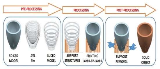
Brackets are the load-bearing components in a satellite. The current age of satellites comprises specific brackets that set out as a link between the bodies of the satellite, reflector parts, and feeder facilities mounted at its upper end. Brackets are used to carry loads of the satellite body frame, supporting elements, batteries, and electronic goods. Additive Manufacturing (AM) is a process in which a 3D solid object is built by adding the material layer-over-layer. The success of making the product using AM technology requires greater experience in Design for Additive Manufacturing (DFAM) which makes use of the design of freedom of AM. Owing to the various advantages of AM and DFAM, it is easy to create high strength-to-weight ratio products. This is an important contribution to aerospace industries in meeting the unabated demand for lightweight and strong structural applications.
- additive manufacturing (AM)
- Selective Laser Melting (SLM)
- bracket
- Ti-based materials
- satellite
- DFAM
1. Introduction
- (I)
-
Omission of smaller part assembly: During the designing procedure, various smaller parts can be replaced by a single part which allows reusearchers to print the complete part at once. Whereas in traditional manufacturing; first, all the components are manufactured individually and then assembled to create the final part [13].
- (II)
-
Minimization of Material waste: Advanced software like topology optimization calculates the best shape for a part and removes unnecessary material without compromising the structural integrity. This helps our engineers to design and produce a lightweight part by advancing the material distribution, which leads to minimizing material waste. For example, Siemens uses generative design software in 3D printing to develop its gas turbine blades. General Motors also uses 3D printing with generative design and topology optimization software, and it aims to reduce the weight of a vehicle by exploring various options for material distribution within a component [14].
- (III)
-
Can easily create highly complex parts: AM overcomes most of the traditional manufacturing limitations to create almost every complex part with enhanced functionality. For example, the cooling channel of injection moulds in the traditional manufacturing method is mostly straight, which leads to slow and inconsistent cooling of a moulded part. The cooling channel in 3D printing is more advanced and can be re-designed according to the requirement, which provides a more homogeneous heat transfer that results in enhanced cooling characteristics [15].
- (IV)
-
Flexibility of material choice: AM process can print almost using any material available; this opens up the possibilities for material innovation. Engineers can explore the limitless option for the better properties of the product. For example, 3D printing of high-performance thermoplastics can replace some metal parts, and it is also low cost and lightweight [16].
- (V)
-
Minimized support structure: Like material innovation, 3D printing also opens up the possibility for unique support structure design. By choosing the best part orientation, the post-processing time and cost can be reduced. Though the supporting system can’t be removed completely, it is very much necessary that a minimum support system should be provided to the 3D model as it can reduce cost prominently. An optimized number of support systems should be provided while designing [17].
- (VI)
-
Lightweight product: Topology optimization provides the advantage to design and manufacture a product for a specific function, and with a made-to-measure feature, for example, unnecessary materials are removed by advanced design and complicated mathematical calculation; therefore, the product part is lightweight and cost is minimized [18].
- (VII)
-
Multimaterial Products can be manufactured: Another crucial advantage of 3D printing is multiple materials can be simultaneously printed into a solid. This solves one of the vital limitations of the conventional manufacturing method [19].
2. Materials Used in Brackets
Material selection is a critical aspect of the aerospace component and system design cycle. It affects many of the performance factors of aircraft such as payload, flight performance, safety, reliability, structural efficiency, energy consumption, disability, lifecycle cost, and recyclability. The material for aerospace structural applications must consist of mechanical, physical, and chemical properties, such as rigidity, high strength, damage resistance, fatigue durability, high thermal stability, low density, excessive corrosion, and oxidation resistance. The material selection depends on various operating conditions like loading conditions, temperature, moisture, corrosion, noise, etc., of that particular component or system. For the brackets used in the wings of an aircraft that sustains bending during service along with torsion, vibration, tension, and fatigue, a material possessing high tensile and compressive strength, stiffness, vibration modes, and buckling strength will be suitable. Similarly, the combustion chamber always interacts with the fluid which is subjected to high temperature and pressure. So, the material for this should have oxidation resistance and principally thermal properties [22]. Despite matching the primary service requirements, the improvement of structural capability in aerospace structural design becomes remarkably important because the function of lightweight arrangement provides an exponential boost in aircraft performance wherein AM plays a significant role in meeting such unique demand. Another effective and more advanced way to achieve lightweight material is structural optimization. In this method, the material is distributed to reduce material, and structural performance is enhanced [23][24][25][23,24,25]. In addition to structural capability, improved acceleration performance, energy efficiency, flight endurance, payload, and decreased life cycle cost and greenhouse gas emissions can also be achieved by the application of DFAM [26]. The various materials used for making brackets and their processing using AM techniques are discussed below.2.1. Al-Based Alloys
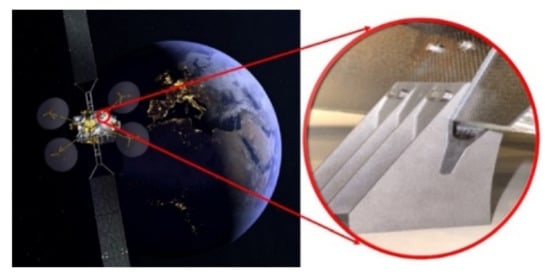
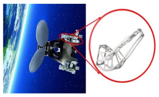
Al6061 is a lightweight material yet high in strength as compared to other aluminum alloys. The important factors to be considered are deflection and stress distribution. In general, good ductility and corrosion resistance, relatively high basic strength and rigidity, low price, and simple manufacturability and durability make advanced aluminum alloys an excellent choice of lightweight materials in many aerospace structural applications such as upper and lower wing skins, wing stringers, and fuselage skin, etc. [27]. On their first human-crewed flight in 1903, Al was the first choice for the engine components and cylinder block for the Wright brothers. For the first time, an Al-alloy was heat-reinforced, a discovery that set Aluminium’s dominance in aerospace engineering [28][29][28,29]. The aluminum added substance layer manufactured (ALM) section saves weight and decreases the making time. More prominent solidness gives better guiding exactness toward mounting receiving wires. Airbus Defence and Space in the UK attempted its first space-qualified aluminum 3D printed segments. The optimized antenna bracket for TMTC is shown in Figure 3. The 3D printed segments being created by the UK group are high-performance structures that cannot be manufactured by conventional techniques. The advanced structural bracket made of Al-alloy was installed in Eurostar E3000 broadcast communications satellites. The bracket is a single-piece laser liquefied part weighing 35% less than the conventionally manufactured part that consists of four sections and 44 rivets. In addition, the ALM section is 40% stiffer. Further, as compared to the part processed using conventional machining techniques, the least wastage is observed. The section is used for mounting the telemetry and telecommand (TMTC) reception apparatuses onto the satellite. From the flight qualification testing of the structure, it was found fit to be flown on an impending satellite [30]. The innovative design in the 8 U Cube Satellite included DFAM-based lattice structures to improve the protection. Some of the latest developments include alloying additions such as Gd, La, Sm, and Yb to improve the high-temperature performance and corrosion resistance of cast Mg alloys [31][32][31,32].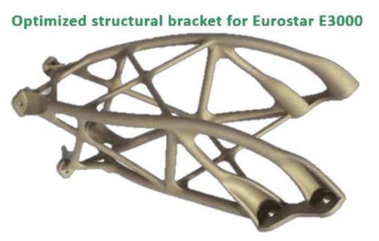
2.2. Ti-Based Alloys
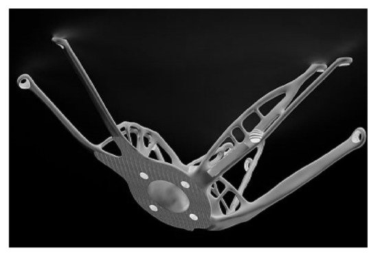
Titanium alloy is a preferred choice of engineering material after aluminum to manufacture aircraft frames and engine components. Although It has paved its way into the aerospace industry manufacturing Ti products have challenges. Firstly, the high cost of alloy, which is nearly eight times that of Al-alloys used in industries. Secondly, machining Ti-alloy is quite a difficult and expensive process due to its high strength and hardness. Hence, an adaptation of Ti alloys is considered only in critical components of aircraft. They are preferred where high strength, corrosion resistance, and space constraint are the deciding parameters for designing components, and also cost of the product must not be that crucial. In general, Ti-alloys are used mainly in manufacturing engine components and the mechanical structure of aircraft. Titanium combinations have a boundless edge over different metals. It has high rigidity, great crack strength, and fatigue resistance, with some erosion resistance, heat resistance, cryogenic embrittlement restriction, and low thermal coefficient. This makes the Ti-alloy an appropriate alternate choice for steel and Al-based compounds used in aircraft applications. Figure 4 shows a simple design of the additively manufactured Ti-alloy bracket. The processing of Ti-alloy-based brackets using AM is also challenging. Benedetti et al. [34] found high porosity and surface roughness along with poor fatigue properties in the Ti-6Al-4V-alloy-made components processed by Selective Laser Melting (SLM). The relationship between porosity, microstructure, and mechanical properties is also analyzed in terms of process parameters and then improving the processing parameters to achieve 99.5% relative density in CP-Ti-made components [35]. Atar et al. [36] reported improvement in compressive strength, toughness, and tensile strength for SLMed structure. Sample production of Ti-6Al-4V alloy using Selective Laser Sintering (SLS) followed by hot pressing was attempted by Das et al. [37]. The Ti alloy structure processed by SLM provides the best strength-to-weight ratio and is about half as heavy-duty steels or Ni-based superalloys. The vast majority of aircraft frames today are made of Ti-alloys. These alloys have a very specific reinforcing body and can suppress the development of weakness on these grounds; they are considered an ideal replacement for steel and aluminum in frames. To prevent catastrophic fatigue, they are used as thin, narrow bracket rings around the aircraft fuselage of aluminum, similar to the belly bar. One of Ti alloys’ main applications in the aerospace industry has been the use of (α + β) Ti3Al2.5V for hydraulic pipes, aircraft floors, piping systems, etc. [38]. Ti-6Al-2Zr-2Sn-2Mo-2Cr-0.25Si is being produced for US F-22 aircraft and joint strike missile projects. Ti alloys such as Ti-3Al-8V6Cr-4Mo-4Zr (β-C) and Ti-15V-3Cr-3Sn-3Al are preferred for generating sources for multi-aircraft activation systems [39]. Currently, Boeing has created 200 unique parts for ten aeroplane stages utilizing AM, and it has delivered around 20,000 sections for military and business aeroplanes, including 32 distinct segments for its 787 Dream liner planes. General Electric, the world’s biggest fly motor provider, produces fuel spouts for a great many fly motors that are processed to have 25% less weight and multiple times more solidness than best-in-class parts, which were recently made by welding 20 unique parts. SLM is considered the most solid AM strategy that can deliver lightweight parts for aviation applications with diminished CO2 discharge. Tomlin and Myer have demonstrated the useful suitability of the Electron Beam Melting (EBM) technique for making Airbus A320 nacelle pivot section segments. The utilization of Ti instead of steel brings about a 63% weight decrease.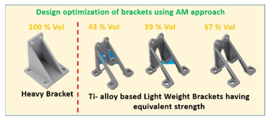
2.3. Stainless Steel
2.4. NiTi-Based Alloys
3. Emerging Applications of Satellite Brackets
3.1. Antenna Brackets
3.2. Reaction Wheel Brackets
3.2. Reaction Wheel Brackets