Your browser does not fully support modern features. Please upgrade for a smoother experience.
Please note this is a comparison between Version 2 by Jessie Wu and Version 1 by Rong Xiang.
The superconducting radio frequency photoinjector (SC RF gun or SRF gun) combines the principle of a photoelectron gun with the application of a superconducting (SC) accelerating cavity. The photocathode is located very close to the SC cavity or directly in contact with it. Since the first concept was proposed by H. Chaloupka in the 1988 EPAC, the SRF gun has been proved to be a successful technology producing high brightness and a high-current beam, which is required by continuous-wave (CW) free electron lasers (FELs) and energy recovery linac (ERL) facilities.
- photocathode
- SRF gun
- photoinjector
1. Requirements for Photocathodes Used in Superconducting RF adio Frequency Photoinjector (SRF Guns)
In general, photoinjectors request that the cathode materials provide enough QE, practical lifetime, low thermal emittance, and fast response time. For practical operation in the electric field and for machine safety reasons, the cathodes need to be particle free, have smooth surfaces, good adhesive features, and low dark current.
Moreover, there are some special requirements for the photocathodes used in SRF guns. Because the cathode will be inserted into or close to the superconducting environment, it needs to be cooled in order to reduce the heat load to the SC cavity. So, special attention must be paid to the material properties at different temperatures, e.g., the thermal conductivity and thermal expansion. Especially when a photocathode is in direct contact with a gun cavity, its transition temperature and critical magnetic field must match the SC working conditions. When the temperature of semiconductor photocathodes is cooled from warm down to cryogenic temperatures, there will be an influence on the crystal’s lattice and the carriers’ density. Therefore, it may change the energy band gap and electron affinity, which directly influence the QE and intrinsic emittance at a certain laser wavelength [11][1].
The heat load from the cathode to the cavity should be taken into account. A part of the cathode drive laser and the RF power deposited on the cathode surface can cause additional heat. If no sufficient cooling is provided for the cathode, this heat might warm up the cathode and even affect the SC cavity. Therefore, the material used for the cathode structure must ensure good thermal conductivity and good thermal contact with the cooling circular.
MP is an unwanted phenomenon limiting the SC cavities’ performance in both elliptical cavities and quarter-wave resonator (QWR) cavities. MP appears when the field-emitted electrons start to resonate in the RF field and the electron numbers are amplified. Thus, the cathodes used in SRF gun cavities need to have a low secondary electron yield (SEY) in order to effectively reduce the MP possibility.
2. Photocathode Assembly
As already mentioned, the integration of a photocathode into an SC cavity represents the key technology for an SRF gun. Up to now, several cathode assembly methods have been successfully applied in SRF gun designs.
The superconducting photocathode can be directly sealed onto the cavity or it is a part of the cavity back wall. In this case, no special assembly method is needed. For example, the DESY SRF gun [12][2], JLab SRF gun [13][3], and Euclid UEM SRF gun [14][4]. The disadvantage is that the cathode cannot be exchanged or is not exchanged in situ.
However, if an NC photocathode is chosen as a photoemitter, there must be thermal isolation between the NC cathode and SC cavity, for example, a vacuum gap. Several RF choke structures have been designed for the cathode holder (stalk) in order to minimize the RF loss to this vacuum gap. The structure of the RF choke cavity is suitable for the 1.3 GHz elliptical cavity guns [5,15,16][5][6][7]. BNL [17][8] and WIFEL SRF gun [18][9] cathode stalk structure is used for the low-frequency QWR cavity gun. If the cathode itself is also electrically isolated from the cavity, a DC bias is able to be loaded on the cathode in order to suppress the possible MP resonance. Because of this vacuum gap, it is also possible to operate the cathode at different temperatures, e.g., cooled with liquid helium (KEK SRF gun), liquid nitrogen (HZDR SRF gun), cold gases (HZB SRF gun, SLAC SRF gun), or even with water (BNL SRF gun).
There is another solution to integrate the NC cathode by using a DC gun outside of the SC cavity, for example in the PKU DC-SRF gun. The vacuum gap between the cathode and cavity is extended until the cathode is located outside of the SC cavity, where the biased cathode and the cavity build a new Pierce DC gun. The Pierce-structure DC part can be kept at room temperature or cooled down to reduce the heat load. Compared to the other RF choke design, the main advantages to moving the cathode out from the cavity into an extra DC structure are little risk of contamination to the SC cavity and no RF heating to the cathode. The disadvantages are the limited DC field on the cathode surface and the drift space between the Pierce DC part and the cavity, which makes this design not suitable for high bunch charge applications.
3. Superconducting Photocathodes
It is possible to choose a superconducting photocathode for an SRF gun to provide enough photocurrent when illuminated with a drive laser but bring no quenching problem to the cavity. The key challenges are to achieve high enough QE by removing the surface contaminations on the cathode and to operate the cathode without changing the SC cavity performance. We introduce niobium, lead, and the plasmonic enhanced cathode based on them in this section. The idea of a thin film multi-alkali photocathode on the SC substratum will be introduced in Section 5.4.
3.1. Nb Photocathode
The QE of a bare Nb surface can exceed 10−5 at 266 nm [19][10]. The most direct solution is to illuminate the back wall of an Nb cavity to generate electron beams, especially for low-current applications, such as CW ultrafast electron diffraction/microscopy (UED/UEM) [14][4], where only <1 pC bunch charge is required. Compared to the exchangeable plug-in photocathode, this method can avoid any possible mechanical difficulties and particle issues.
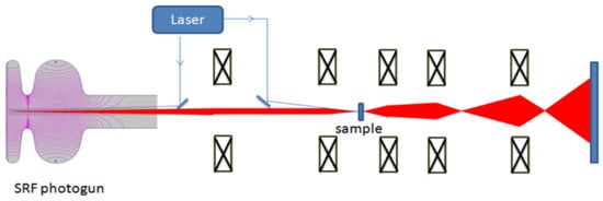
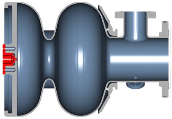
The design of the Euclid SRF gun is a good example (Figure 1). This is a CW, 1.5-cell SRF gun operating at 1.3 GHz for MeV UED/UEM applications. The cavity itself is coated with Nb3Sn, but the back wall center is bare Nb with a high residual resistivity ratio (RRR) used as a photocathode. An ultra-violet (UV) laser with milliWatts power illuminates the back wall of the SRF cavity to provide the required bunch charge ≤ 500 fC. The back wall photocathode must be robust because no exchange cathode is available. Of course, the metal photocathode is more robust against vacuum spikes and ion back-bombardment than the semiconductor cathodes.
Because the required laser power is very low, the heat effect on the local area is limited. The cooling efficiency through the back wall should be good enough to maintain the superconducting status at the cathode area.
3.2. Pb Layer on Nb
A project of all superconducting RF guns at DESY belongs to the CW-XFEL project [3][11]. It has a 1.6-cell, 1.3 GHz superconducting gun cavity with a lead cathode located in its back wall. Because a high bunch charge up to 1 nC is required for the XFEL facility, with the existing laser system, the QE of niobium is too low [19][10]. However, the QE of another superconductor, lead, is sufficiently high [20][12]. A test with the Pb-coated cathode plug has been conducted with an HZB SC RF gun [21][13].
In the work of [21[13][14],22], the lead film was deposited in the cathodic arc and then was treated with an ex situ smoothing process, re-melting and recrystallizing with pulsed plasma ion beam bombardment, followed by in situ laser cleaning treatment. This smoothing process could improve the surface conditions. The lead layer showed a very good QE of 2.7 × 10⁻³ at 213 nm after the laser cleaning.
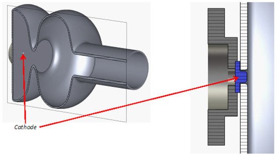
The DESY SRF gun cavity and its cathode are still under development. The first cavities with a lead-coated back wall suffered from problems with cathode surface quality [12][2]. The cavity performance with a coated Nb plug was degraded compared to the test with an uncoated Nb plug. A recent attempt was made to use the Nb cathode plug screwed into the hole at the cavity back wall (Figure 2). The plan was to clean the coated cathode surface with a laser after cathode insertion in the clean room. However, there is a high risk that the lead particles falling down from the cathode might heat and quench the cavity. Another challenge is the exchange progress of the cathode. The cathode exchange must be performed when the cavity is warmed up and sent back to the clean room. Thus, from the practical operation side, it is only reasonable when the cathode can provide a year-long lifetime.
However, more experimental results are needed to verify the feasibility and reliability of this design. The superconducting status at the cathode area can be maintained only when the heat power from the drive laser is limited and can be efficiently cooled by the back wall.
3.3. Nb Cathode with Plasmonic Enhancement
A metallic photocathode with a nano-patterned surface will obtain plasmonic effects to increase the absorption of light and enhance the local electromagnetic field intensity [23,24][15][16]. This effect can be also used for the superconducting photocathode material, for example, niobium. The team from Jlab and RadiaBeam has proposed a promising new design with a 1.6-cell 1.3 GHz cavity and a special cathode plug cooled with liquid helium (Figure 3).
There are different approaches to obtaining the plasmonic enhanced surface. One method is to fabricate a rectangular array of subwavelength nanostructures with a focused ion beam (FIB) milling onto the metallic surface. This designed nano-pattern can excite properly tuned surface-plasmon response. In the experiment using nano-patterned niobium at room temperature (typical work function ~4.2 eV ~296 nm) [13][3], the measurement of charge density versus 1030 nm laser intensity suggested that four-photon emission appeared, corresponding to an effective QE of 1.4 × 10⁻⁵.
Another method described in [25][17] is to deposit a low work function material, such as magnesium (Mg), onto the Nb surface and ultra-thin islands of indium (In), which produces the deep UV plasmon resonance and improves the QE by >400 times.
This technique is a promising step to realizing high-QE superconducting photocathodes. At the moment, no reports about the operation performance of SRF guns have been published. There is a potential risk of quenching due to high laser power on the cathode. For the plasmonic cathode, the number of photoelectrons increases nonlinearly with the photon numbers. The higher the laser pulse energy, the higher the achieved QE. A balance must be reached between enough laser energy for photoemission and the heat load to the cathode. Thus, the maximum repetition rate of the electron source might be limited by the cathode quality. Furthermore, the cooling of the cathode area is an essential key for successful operation in the future. The special cooled plug design like at JLab (in Figure 3) is needed to enable cathode treatment outside of the cavity and to enhance the thermal conductivity with proper plug materials.
References
- Xie, H.; Ben-Zvi, I.; Rao, T.; Wang, T.X. Experimental measurements and theoretical model of the cryogenic performance of bialkali photocathode and characterization with Monte Carlo simulation. Phys. Rev. Accel. Beams 2016, 19, 103401.
- Vogel, E.; Barbanotti, S.; Brinkmann, A.; Iversen, T.B.J. Status of the all superconducting gun cavity at DESY. In Proceedings of the 19th International Conference on RF Superconductivity, Dresden, Germany, 30 June–5 July 2019.
- Hannon, F.; Andonian, G.; Harris, L. A Plasmonic niobium photocathode for SRF gun applications. In Proceedings of the 10th International Particle Accelerator Conference IPAC2019, Melbourne, Australia, 19–24 May 2019.
- Liu, A.; Kostin, R.; Jing, C.; Avrakhov, P. Optimization of an SRF gun design for UEM applications. In Proceedings of the 3rd North American Particle Accelerator Conference (NAPAC2019), Lansing, MI, USA, 1–6 September 2019.
- Konomi, T.; Honda, Y.; Kako, E.; Kobayashi, Y.; Michizono, S.; Miyajima, T.; Sakai, H.; Yamaguchi, K.U.S. Development of high intensity, high brightness CW SRF gun in KEK. In Proceedings of the 19th International Conference on RF Superconductivity (SRF 2019), Dresden, Germany, 30 June–5 July 2019.
- Teichert, J.; Arnold, A.; Ciovati, G.; Deinert, J.C.; Evtushenko, P.; Justus, M.; Xiang, R. Successful user operation of a superconducting radio-frequency photoelectron gun with Mg cathodes. Phys. Rev. Accel. Beams 2021, 24, 033401.
- Neumann, A.; Böhlick, D.; Bürger, M.; Echevarria, P.; Frahm, A.; Glock, H.-W.; Göbel, F.; Heling, S.; Janke, K.; Jankowiak, A.; et al. The bERLinPro SRF photoinjector system-from first RF commissioning to first beam. In Proceedings of the 9th International Particle Accelerator Conference (IPAC2018), Vancouver, BC, Canada, 29 April–4 May 2018.
- PetrushinaI, I.; Litvinenko, V.; Jing, Y.; Ma, J.; Pinayev, I.; Shih, K.; Wang, G.; Wu, Y.; Altinbas, Z.; Brutus, J.; et al. High-brightness continuous-wave electron beams from superconducting radio-frequency photoemission gun. Phys. Rev. Lett. 2020, 24, 244801.
- Legg, R.; Bisognano, J.; Bissen, M.; Bosch, R.; Eisert, D.; Fisher, M.; Green, M.; Jacobs, K.; Kleman, K.; Kulpin, K.; et al. Status of the Wisconsin SRF gun. In Proceedings of the IPAC2012, New Orleans, LA, USA, 20–25 May 2012.
- Smedley, J.; Rao, T.; Zhao, Q. Photoemission studies on niobium for superconducting photoinjectors. J. Appl. Phys. 2005, 98, 043111.
- Decking, W. A MHz-repetition-rate hard X-ray free-electron laser driven by a superconducting linear accelerator. Nat. Photonics 2020, 14, 391–397.
- Smedley, J.; Rao, T.; Sekutowicz, J. Lead photocathodes. Phys. Rev. ST Accel. Beams 2008, 11, 013502.
- Barday, R.; Burrill, A.; Jankowiak, A.; Kamps, T.; Knobloch, J.; Kugeler, O.; Matveenko, A.; Neumann, A.; Schmeißer, M.; Voelker, J. Characterization of a superconducting Pb photocathode in a superconducting rf photoinjector cavity. Phys. Rev. Accel. Beams 2013, 16, 123402.
- Lorkiewicz, J.; Nietubyć, R.; Diduszko, R.; Sekutowicz, J.; Kosińska, A.; Mirowski, R.; Kuk, M.; Trembicki, A. Coating in ultra-high vacuum cathodic-arc and processing of Pb films on Nb substrate as steps in preparation of Nb-Pb photocathodes for radio-frequency superconducting e-guns. Vacuum 2020, 179, 109524.
- Zhang, Z.; Li, R.; To, H.; Andonian, G.; Pirez, E.; Meade, D.; Maxson, J.; Musumeci, P. Surface-plasmon enhanced photoemission of a silver nano-patterned photocathode. Nucl. Instrum. Methods Phys. Res. Sect. A Accel. Spectrometers Detect. Assoc. Equip. 2017, 865, 114–118.
- Li, R.K.; To, H.; Andonian, G.; Feng, J.; Polyakov, A.; Scoby, C.M.; Thompson, K.; Wan, W.; Padmore, H.A.; Musumeci, P. Surface-Plasmon Resonance-Enhanced Multiphoton Emission of High-Brightness Electron Beams from a Nanostructured Copper Cathode. Phys. Rev. Lett. 2013, 110, 074801.
- Asalzadeh, S. Strong Plasmonic Enhancement of Photoelectric Quantum Efficiency of Nb Using in Nano Islands; ProQuest Dissertations Publishing: Ann Arbor, MI, USA, 2020.
More


