TEV chis paper proposes a design for the Barging requires either single-phase or three-phase charging stations that have unidirectional electric vehicle charger which is capable of doing both the Grid to Vehicle and Vehicle to Grid power transfer, and the intenal or bidirectional power flow capabilities. Moreover, EV charger can make use of traction will be made through an automatic smart energy management system(EMS). A simplepowertrain equipment to achieve high power electronics topology is used. The user can adjust the output of this charger by using the control signal provided by the controller. The simulation result obtained shows that it has an interaction between the charger and an Energy Management System(EMS) in a residencedensity and weight reduction in order to save space in the vehicle while increasing efficiency.
1. Specifications
Genormous number of automobiles across the world has caused a significant increase in emissions of greenhouse gases, which pose a grave and mounting threat to modern life by escalating global warming and polluting air quality. These adverse effects of climate change have motivated the automotive sector to reform and haveally speaking, an electric vehicle charging station should comply with the following specifications and deliver a number of other functions, particularly durability, efficiency, and performance:
-
Implement a power factor correction: absorb a sinusoidal current free of harmonics with a power factor equal to 1.
-
Bidirectional power electronics topology that allow participating to the energy storage on the grid in order to implement a vehicle-to-grid or vehicle-to-home concept.
-
Using the traction inverter in the EV charging power electronics.
-
No additional filtering inductance by using traction motor windings.
-
Possibility of balancing battery elementary cells by implementing a part of battery management system functions.
-
Contactless power transfer.
2. Power Electronics Solutions
To pushmed the drive towards the transformation to fully electric. Cet these EV charging time has been identified as one of the key barriers in large-scale applications of Electric Vehicles (EVs). In addition, various challenges are associated with the formulation of a safe charging scheme, which is concerned with appropriate charging converter architecture, with the aim of ensuring a safe charging protocol within a range of 5–10 min. This paper provides a systematic review of thharging technologies and their impacts on battery systems, including charger converter design and associated limitations. Furthermore, the knowledge gap and research directions are provided with regardstations requirements, several power electronics solutions have been proposed and implemented by car manufacturers and energy providers. These solutions are briefly presented and discussed in the following subsections. The readers may refer to the challenges associated with the charger converter architecture design at the systems level.
1. Introduction
Refollowing paper for more details on power elec
ent
ly, Electric Vehicles (EVs) have gained popularronics configurations [6].
2.1. Unidirectional Battery Charger
Uni
ty over tradi
rectional
fossil fuel-based automobiles, which cause environmental pollution by releasing greenhouse gas emissions (GHG) [1,2,3,4]. EVchargers have a diode bridge rectifier (DBR) ass
no
t only curtail carbon emissions but also reduce the burden of fossil fuel dependency [5].ciated with a filter stage and a KeyDC/DC bottlenecks in enabling larger EV adoption includeconverter, as shown in Figure 1. tThe
high cost due to batteries, range anxiety dueDBR can be either single-phase (Figure 1) to
reduced battery capacity and speed, high charging time, and lack of sufficient charging infrastructures [6,7,8]. To meet r three-phase to increase the cha
llerging
e of time, it is possible to develop highly efficient, reliable, and compact EVs by enabling game-changing battery charging technologies with the aim of reducing power. Moreover, a high frequency isolation transformer is used to ensure isolation during EV charging
time and enhancing battery capacity [9,10,11]. It is . This converte
xpectedr t
hat EV penetration by 2030 will be approximately 30% of all vehicles sold that will be either electric-powered or hybrid [12]. China, opology does not have the ability t
heo US, and Europe are, so far, the biggest EV exporters worldwide, and the sales volume of EVs increased at a rate of 94% between 2011 and 2015. The Li-ion battery itself accounts for 40% of the total production cost of EVs. Prices of Li-ion batteries were reduced from $600 per kWh in 2012 to $250 per KWh in 2017 [13]. The recent tuse EV battery as energy resource and then inject power to the utility grid. However, it a
rget is set tllo
push the price drop further to $100 per KWh by 2024. EVs have become a hot topic of research since 1990, therefore it is important to understand the development trend and technological barriers.
Charging ws providing ancillary services, mainly voltage regulati
me is the key bo
ttleneck, particularly for Battery Electric Vehicles (BEVs), where it ranges from 2 to 6 h [14]. Thren, by supplying or absorbing reactive power from the
clma
ssifications have been made by the U.S. Department of Energy based on in grid without EV battery discharging
EV power capac.
Figure 1. Unidirectional battery charger for EVs.
Uni
ty. The fdir
st includes charging EVs at less than 5 kW [9,15,16], ectional batt
he
second covers the fast-charging power range between 5 and 50 kW, and the last one denotes a charging power range greater than 50 kW [17]. The fry chargers offer a simple and easy-to-control soluti
rst two
are referred to as on-board chargers that are integrated into the vehicle, while the third one is referred to as an off-board charger, which is basically equivalent to a fuel station [18]. Thn to manage EV fleet and meet the requirements for safe, reliable, and cost-compe
reduct
ion in the size of the off-boarditive EV charg
er is the future focus of research. Still, the on-board charger can charge the battery on a domestic load. However, the mileage capacity is restricted to 240–300 Wh/mi [19]. Thusing solution. However, with the increasing penetration of EV in the transportation sector, i
f t
he vehicle is nee is intended to
make an extra trip urgently outside the daily drive, it would require fast-charging solutions.
EV cplay a key role in th
arginge systems can be categorized into three groups based on the power levels, as shown in Table 1. Usualmain grid regulation (mainly,
thfreque
chargers with a power level below 3.3 kW (1-phase) are termed slow chargers or Level 1 chargers with 120Vac outletncy and voltage regulation), which can
be integrated in-to the vehicle power train (on-boardnot be totally ensured using unidirectional EV charger
) or can be installed as a convenience outlet at home (wall-charging outlet). The charging time for Level 1 charger is higher which is 4–11 h for 1.4 kW (for PHEV battery of 5–15 kWh capacity) and 11–36 h for 1.9 kW (for EV battery of 16–50 kWh capacity). Level 2 chargers can charge EV batteries with a power of up to 22 kW for both 1-phase and 3-phase with 240Vac (US standard) and 400Vac (EU standard)s. Consequently, there is a need for bidirectional power flow topologies that allow EVs to act as a distributed energy storage on the power system [
20127,128].
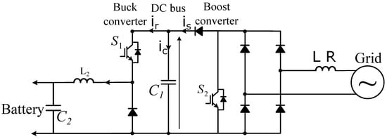
S 2.2. Bidirectional Battery Charger
Bi
mdi
lar to Level 1rectional EV chargers
, they can either be part of the vehicle or part of the dedicated Electric Vehicle Supply Equipment (EVSE) outside the vehicle. Three types of charging time scenarios are available for Level-2 charger such as 1–4 h for 4 kW with PHEV battery capacity of 5–15 kWh, 2–6 h for 8 kW with EV battery capacity of 16–30 kWh and 2–3 h for 19 are composed of two stages, which are a single-phase or three-phase active front end (AFE) followed with a bidirectional DC/DC converter, as depicted in Figure 2.
2 kW with EV capacity of 3–50 kWh [20]. OAFE is a bidirection
al the other hand, Level-3 chargers have power levels up to 200 kW and they are always outside the vehicle as a part of EVSE. Level-3 charger has both ac and dc power facilities with voltage outlets of (208–240) Vac and (200–600) Vdc. It is mostly applicable in commercial area analogous to a filling station. It is termed as fast charging prototype due to its less charging time which is 0.4–1 h for 50 kW prototype and 0.2–0.5 h for greater than 90 kW prototypeAC/DC converter that allow regulating the DC bus voltage and controlling quasi-sinusoidal grid currents, while ensuring a unity power factor (current phase angle control) or exchanging reactive power with the power grid. The
battery capacity of the dedicated EVs ranges from 20–50 kWh [20]. Asecond stage allows controll
ing th
ree types of chargers convert AC grid voltage to suitable DC voltage to charge the e charging current of the battery. The
power levels determine how fast the battery will be fully charged from a specified state-of-charge (SOC) level [21].
Table 1. Charging characteristics and required infrastructure of some manufactured PHEVs and EVs (data collected from [14,15,16]).
The DC/DC converter can be either isolated or non-isolated c
hargi
ng characteristics and required infrastructure of some of the commercially available Plug-in electric vehicles (PEVs) and EVs are shown rcuit configurations as discussed in
Table 1[6].
Most of tTh
e vehicles have either a Level 1 or Level 2 charger as a part of their vehicle power train (on-board chargers). However, Level 3 fast charging is the quickest option to charge any EV battery if the required connector is available in the vehicle.
Ais converters topology offers a bidirectional power exchange with the main grid to support the grid during congestion periods and behave U.S.as Department of Eadditional energy
report in 2008 [22] pointestorage d
ou
t that charging location is critical for buring off-peak periods.
Figure 2. Bidirectional battery charger for EVs.
Bilding future EV mobility and classified the locations for EV rectional charging into three groups: (i) Residential garage charging (Level 1 and Level 2), (ii) apartment complex charging (Level 1 and Level 2), and (iii) commercial facility c has several advantages compared to unidirectional charging (Level 2 and Level 3). For both the home and apartment scenarios, it is assumed that a majority of the. During EV charging will be performed at night. For commercial facilities, it is assumed that charging is primarily performed during normal business hours.
Soperation, it has been shown that the use of bidire
veral revcti
ew papers ononal charging
technologies of EVs can be found in the literature based on a number of factors [23,24].can increase the benefits by Inat [25], lea
st 25% comp
are
hensive review of EV charging station infrastructure, standards of d to standard unidirectional charging
cables, cords, and connectors, the impact of semiconductors devices used in converters on charger performance and cost, and the integration of athrough the vehicle-to-grid (V2G) principle. In bidirectional charging
system with the microgrid for better energy management systems have been analyzed. The technologies related to EVs, EV charging systems, and optimization strategies to obtain the available output have been represented in another review [26]. A, the use of the battery capacity of EVs can also contribute to ancillary services, such as maintainin
g overview of the recent EV market, standards related to charging, grid integration and safety, charging infrastructure, and effects of EV penetration are discussed in [24]frequency and voltage at the nominal levels and controlling congestion risks.
AIn
overview of the diverse kinds of EVs that are commercially available and associated with deed, this distributed energy s
torage systems (ESS), as well as a detailed review of public and residentialystem allows can provide/absorb active power
outlets, EV charging cords, and charging stands based on various power levels, was discussed in [27]. The nto maintain nominal grid frequency (global parameter) and supply/absorb re
ga
tive impact of EV charging on the utility grid and the safety code associated with EVctive power to regulate voltage level (local parameter). 2.3. Integrated On-Board EV Charger
AC charging
sty
stems has also been analyzed. A converter is an integral part of the EV charging system [28]. In [29], a review of pically needs an on-board AC/DC power converter
. architectures,Quite inter
national standards, and EV charger manufacturers was analyzed. The architecture of theestingly, the motor and the motor drive inverter, which conver
ter topologies and the reliability associated with these topologies are considered to be important factors to evaluate the effectiveness of these converter topologies, which were not considered in the aforementioned studies.
Diffets the DC power from the battery into AC power for the motor, can also be used as the on-board charger for the batter
enty factors[129]. have to be coIn
sidered to design the converter topologies of EV chargers, such as the efficiency, power factor, isolation, harmonic contents, filter, and switching components [30,31,32,33], whdeed, the existing devices of the drivetrain are reconfigured with mini
chmum have been highlighted in this paper for both DC-DC and AC-DC converters. The reliability of electronic coadditional components
associated with EV converter technology ensures the reliable performance of the entire system [34,35].to allow recharging. This eliminates the need for Relia
bility assessment of the separate AC/DC power
electronics conconverter f
rom manufacturer, seller, and customer standpoints is crucial to verify the reliable operation of the EVs in all environmental conditions [36,37]. Adaptation of or the on-board charger. Since the drivetrain power converter is us
ua
fe and reliable charging methods ensures a long lifetime and better performance of EV batteries by limiting the temperature [38]. The developmelly high power (greater than
t of the fast-charging converter accelerates the revolution toward sustainable transportation through EVs [39,40].100 kW), this also means that the EV can There
fore, different charging methods and ach quite high charging
strategies are important factors in evaluating the total performance of the EV. EV technologies are facing various crates (greater than 22 kW). The challenge
s such as slow charging, isolation, power loss due to converter structure, power electronic component reliability, and thermal condition of EV batteries [41]. Ve is to design the motor drive and its control to provide th
icle
to Grid (V2G) is not only a promising solution to cope with a large number of EVs considering all the aspects of charging and discharging EVs but also a possible way to boost economic growth dual functionality of EV charging when stationary and EV propulsion when in motion [
42130,
43131].
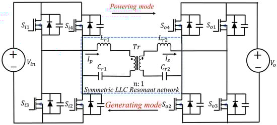
Cl Integrarly, the need to develop reliable and fastted on-board EV chargers is not only important to remove the range barrier, but also to improve the robustness of the EV in the energy transfer context. Therefore, the specific goal of this review is to provide a detailed overview of the current development of the charging converter architecture and converter reliability, highlighti is a bidirectional EV charger that uses a single inverter/rectifier for all operation modes of EV. This topology allows minimizing the challenges and potential solutions related to EV charging.
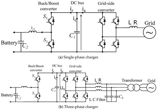
Thenumber of power electronic rdeview started by collecting the latest journal papers from major databases such as Scopus and the Web of Science with keywords including EV Charging, EV Charger Converter, EV charger/converter reliability, Thermal challenges in EV charginces since the same power switches are used both for EV traction/propulsion, braking, and Vehicle to Grid. One hundred and forty papers were selected for this review with particular focus given to the key topics related to EV converter topology and reliability andbattery recharging. This way the cost, size, and weight of EV charging. This paper first reviews and presents available converterer are considerably reduced. A topologies of both AC-DC and DC-DC converters for charging architectures. An overview of the reliaby of such power conversion system is provided in Figure 3 ilityn analysis of EVs and EVwhich the same converters with diverse reliability assessment methods to ensure reliable converter performance and future trends related to EV converter is used for supplying the motor and recharging EV battery. In Figure 4, topologies have been discussed. Various EV charging methods and strategies are presented, highlighting the charging challenges, thermal challenges of the battery, and V2G as potential solutions. Finally, insights into the fundamental charging protocol and guidelines for new research directions are provided.
2. EV Converter Topology
Te on-board charger configuration uses the traction inverter as well as the motor windings. The motor windings of each ph
ase
EV charger usually creates a non-linear load in the power system, which causes problems such as weak power factor and excessive total harmonic distortion in the network. A well-designedare split into two equivalent parts and then reconnected in reverse to cancel the torque in battery charge
r aims not only to safely charge the battery pack with high efficiency but also to meet international standards such as IEEE 1547 [44]. T mode. Motor winding acts as an inductor filter so that the
refore, all EV chargers need a power factor correction (PFC) stage, an isolation stage, and filtering components. Several power electronics converter topologies are proposed in the literature to achieve these. The 6line currents are smooth sinusoidal currents with low THD [132].
6 kW prototype proposed by Lee et al. [45] usAn excellent e
d xa
single-phase PMW rectifier in the first stage and a full bridge resonant converter in the second stage. The rated efficiency in both charging and dismple of this implementation is the Renault ZOE EV, which provides 43 kW on-board AC fast fast charging
modes was approximately 93%, but the power density was poor (less than 1 kW/L). The prototype used Silicon (Si) super-. The Renault has claimed to use a junction
MOSFETs in the power stage. A three-phase 10 kW prototype based on a three-phase active rectifier and a dual active bridge converter proposed by Zeljkovic et al. [46] (Infbox that helps in modifying the operati
neon
) showed approximately 91% efficiency for the worst battery charging condition (195 V), with the topology presented in Figure 1. The pro of the motor and motor drive components to
typ be
mostly used Si devices except for the high-voltage section of the dual active bridge (DAB) where Silicon Carbide (SiC) JFETs (Junction Field-Effect Transistors) were usedused as an on-board EV charger.
Figure 3. Bidirectional battery charger for EVs using traction inverter.
Figure 14. Three-phase on-board charger topology based on active rectifier and single DAB.
2.1. Development Trend of DC-DC Converter
Bidirectional battery charger for EVs using traction inverter and motor windings.
The
DABmain topologyissue with the
series-resonant converter (SRC) topology and two-stage series-resonant converter topology were compared for the DC-DC stage ofse integrated on-board EV chargers is the produced motor torque due to the c
harger. It was found that the two-stage SRC was more efficient compared to the DAB topology. However, the analysis was shown for a 12 V battery charger (auxiliary charger) rather than the mainurrent flowing in the motor windings. One solution to control the torque is to use a mechanical brake during battery char
ger of the vehicle. SRC and two-stage SRC topologies are shown inging. Other solutions that depend on the motor type can be Figure 2 amen
d Figure 3, respecti
vely [47].
Figure 2. SRC DC-DC converter topology.
Figure 3. Two-stage SRC topology.
A mo
difined
DAB converter topology for an EV charger was proposed in [48],: In the case of AC motor w
hi
ch uses a turned L-C-L network to improve the efficiency oth wound rotor, cutting off the
converter by reducing the reactive currents in the active bridges. Although the topology reduces the capacitor requirements of traditional DAB topology, the additional L-C-L filter could increase the overall volume of the converter.
Severalexcitation cancels the magnetic field of the rotor. Therefore, the interaction between the stator and rotor magnetic fields is canceled and the zero torque condition is ma
dvanced modulation strategies have been proposed to reduce the reactive current in the active bridges such as pulse-width modulintained during charging. However, even if the excitation
(PWM) with phase shift [49is switched off,
50,51,52] and tr
iangular and trapezoidal modulation [53,54]. Teluctant torque may occur, causing the
se advanced modulation schemes also extend the Zero-Voltage Switching (ZVS) range and increase the low-power efficiency of the DAB topology. Reactive currents can also be reduced by combining the phase-shift modulation with equal PWM in corresponding bridge switches [55]. A compomachine to vibrate or even rotate. In the case of a permanent magnet synchronous motor, since it has no starting torque, the s
it
e modulation scheme was proposed in [56] for aator wind
vanced in
dependent PWM control of individual switching devices, as well as phase-shift, which improves the low-power efficiency of the topology significantly. This is due togs of the three-phase machine can be connected to the grid without the r
educed root mean square (RMS) current in each switching deviceisk of rotor rotation. However,
the control algorithm is complex and needs to change the modulation strategy at different load conditions.
Tvibrations may still occur. Moreover, the integrated on-board EV ch
arge
authors in [57,58] rs pr
opoese
d the CLLC-based SRC topolognt other drawbacks as follows:
-
Need for a specially designed electrical machine;
-
Difficulty in accessing the neutral point of motor windings;
-
Reduced reliability due to the use of mechanical contactors.
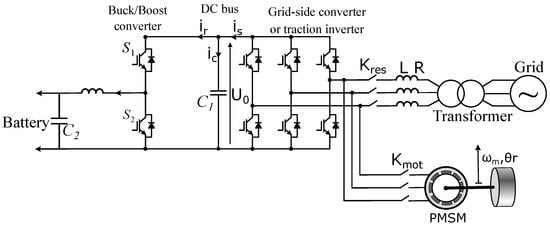
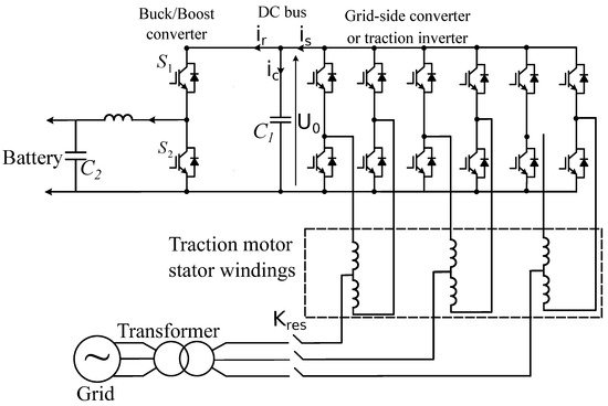
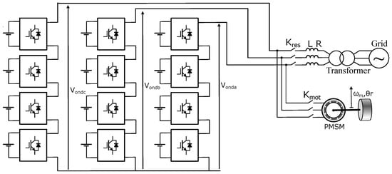
2.4. Bidirectional Battery Charger Using Modular Multilevel Converters
This ty
pe for EVof embedded charg
ing applications. However, it is clear from their research that the CLLC resonant network design in the SRCers use modular multilevel converters (MMC), which are more attractive than two-level converters and neutral point clamp converter
is much more complicated than the DAB s. MMC is an advanced voltage source converter
design. Furthermore, the voltage gain is very sensitive to various parameters, such as the secondary transformer voltage, load condition, inductance of the inductors, and capacitance of the capacitors in the CLLCthat has competitive advantages such as output power high quality, high modularity, simple scalability, fault tolerant capability, and low voltage and current rating demand for the power switches [133,134]. In
etwork. Compared to the DAB topology, the voltage gain equation in CLLC SRC is much more complicated. To design the parameters in CLLC SRC, all the variations in different parameters should be considered. Even for charging mod recent years, the incorporation of wideband gap semiconductors (SiC and Gan) are investigated to implement the MMC application with further advantages of high-voltage and
discharging modehigh-power operations
of the EV charger, the topology might require different CLLC parameters to optimize the performance, which significantly complicates the design procedure.
Another, low power losses, high efficiency, improved reliability, and reduced module crsi
tical issue with CLLC SRC is that the control compze and cooling system [135,136]. Mul
exit
y is greatly increased when compared with the DAB topology.ilevel cascaded H-bridge converter is the best suited for Table 2 rbatte
pr
esents a comparison of various topologies utilized in they charging applications [137,138]. DC
-DC stage of EV coonverter topolog
ies for different types of EV chargers.
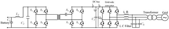
Thy using an MMC at battery cells leve
l dual active half-bridge (DAHB) conto achieve both the traction inverter
is another promising DC-DC topology for EV fastand on-board battery charger
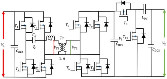
s, which is presented in is shown in Figure 45. [59].In Almot
hough this topology has a smaller number of semiconductor switches than the DAB topology, maintaining the closed-loop control stability is vor mode, power flows from the batteries to the motor through the cascaded inverters. Cascaded inverters can also be used as rectifiers in battery cha
llenging inrging mode [139,140]. It
his topology due to the low-frequency resonance issues. The ZVS range with traditional phase-shift modulation is very limited as well. An advanced asymmetrical modulation strategy is needed to resolve the stability issues and extend the ZVS range is possible to use the motor windings as an inductor, but it is more appropriate to use small external inductors.
Table 2. Comparisons of various topologies for DC-DC stages.
Figure 45. DAHB converter topology.
2.2. Development Trend of AC-DC Converter
Al
Bidirectional battery charger using multilevel modular converters.
2.5. Contactless Power Transfer-Based EV Charger
Induct
ive ch
ough three-phase diode rectifier [20] (unidirecarging is the best alternative t
io
nal topology) and 2-level active PWM rectifier [46] conductive char
ge
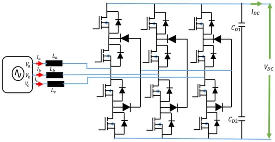
the two most popular topologies for the AC-DC stage, several other topologies have been found in the literature, which reduces the filtering requirements at the PFC stage of the EV charger. For example, [62,63] prrs due to the many advantages that this technology offers. In fact, this charging mo
posde
d a three-level neutral-point clamped (NPC) phase-leg-based AC-DC converter topology, which is presented in has the following advantages: accessibility, standardized charging, Figure 5. Be
ca
use of
the three-level operexchanging of information
and the PWMwith the vehicle [141], modula
tion strategy, the topology can reduce the input filter size. Although the voltage rating of each semiconductor device is reduced, the number of semiconductor devices is doubled compared to the two-level active rectifier, which cannd safety for the user since there is no electrical contact and the heavy cables are eliminated. This can considerably reduce the
power density of chargers greater than 10 kW.
Figure 5. Three-level NPC boost AC-DC converter topology.
A weight of the vehicle and, th
ree-level T-NPC PWM boous
t rectifier-based charger topology was proposed in [64], its energy consumption.
ThInductive
11 kW charger achieved an impressive 95.6% peak efficiency and 2.5 kW /litercharging is based on wireless power
density by employing a multi-port designtransfer principle [142,143], a
pproachs and a novel phase-shift PEM modulation strategydepicted in Figure 6.
AgaiIn
, the number of semiconductor devices, three times that of the two-level this configuration, the grid AC voltage is rectifie
r, is the main issue in this topology.
Krishnamoorthyd using et a
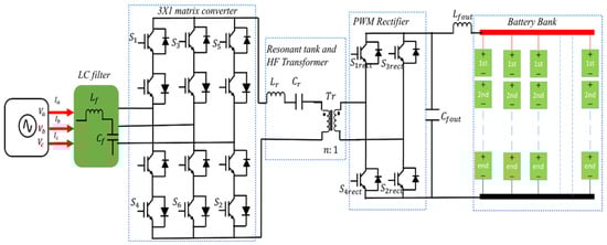
l. [65]n AC/DC proposed a matrix converter
(AC to AC) for EV fast-charging applications, which does not require the traditional AC/DC/DC structure. The topology is presented in Figure 6. The with a power factor correction (PFC) to ensure unity power f
actor
ont-end matrix converter converts the three-phase 50/60 Hz AC and to adjust the rectified output voltage
to single-phase high-frequency AC voltage. The high-(which is usually around 400 V). A high frequency
transformer creates the galvanic isolation and the PWM rectifier rectifies the high-frequency AC voltage to DC inverter is fed by the DC output voltage
suitable for the battery. This topology ensures single-stage power conversion and removes the DC link capacitor at the output of the conventional AC-DC stage, producing a square voltage wave at a frequency of 85 kHz [144]. The
high-fre
fore, matrix coquency inverter
s usually achieve higher power density when compared to traditional two-stage solutions [66,67].
Figure 6. Matrix converter topology with resonant tank and HF transformer for EV charger.
T is followed by an impedance matching network (IMN) eliminating the
acu
thors in [68] rrent harmonics pro
posed
an advanced modulation strategy to uced and compensat
eing for the reactive power d
rawn by the input filter, which reduces the input current distortion and ensures very low total harmonic distortion (THD) for the input current. The controller achieves good dynamic performance in both the charging and discharging modes of the EV battery. However, the matrix coue to the leakage inductance of the transmitting coil, this block is also known in the literature as the primary compensation stage. When the transmitter coil is fed with the filtered output voltage of the inverter
has twice the number of semiconductor devices compared to the two-level PWM rectifier, which could reduce the power density of the charger. Table 3 r, it produces a time-varying magnetic field that can be directed towards the receive
pr
esents a comparison of various topologies discussed in this paper for the AC-DC stage of EV converter topologies for different types of EV chargers.
Table 3. Comparisons of various topologies for the AC-DC stages.
3. EV Converter Reliability
Every coil using ferrite cores allowing wireless power electr
onic system is developed with individual parts or components. Therefore, if any single part fails then it may affect the entire system. From the manufacturing point of view, it is important to ensure high-quality products are delivered to the customers. They should also ensure that the product will perform consistently under various operating conditions. The key driving factors for reliability issues are the massive adoption of electronic systemsansfer from the ground assembly to the vehicle assembly. The time-varying magnetic field induces an AC voltage in the receiver coil at the same frequency as primary coil voltage. This voltage is applied to a secondary compensation stage (IMN) and the
ir increasing complexity. In addition, customers are expecting high reliability from their desired product. For examplen rectified. The rectifier can be a controlled rectifier or diode-based rectifier [145,
146]. iIn
modern electric drives, power electronics converters with associated components together work as a power processor mainly for charging the batteries and deliveringbidirectional systems, a controlled rectifier is required to ensure a bidirectional power
to another auxiliary load. Trends of the power converter areflow to implement the V2G concept [147,148,149]. shiftFin
g toward becoming small in size, compact, efficient, and power dense. They have been popular in EVs due to their ease of ally, a buck-boost DC/DC converter is used to control
and flexibility in scaling. However, the poorthe current delivered to the battery.
Figure 6. Contactless power transfer for EV charging.
3. Summary on EV Charging Stations Technical Requirements
EV char
eliability of these devices is an issue, and they fail frequently; therefore, to ensure the religing modes varies according to several criteria related to efficiency, durability
of this product, this important issue needs to be considered [69].
Th, performance, and cost. Several power e
le
xtreme use of fossil fuels in the transport sector has contributed to environmental pollution over the past decades. The automotivectronics architectures have been investigated in academia and implemented in industry
has introduced a new concept for. With the evolution of the vehicle
s by replacing fossil fuels with electricity, as the driving force in electric vehicles (Evs) [70]. Thus, Evs a electrical system and the increase in charging p
powe
ar to be the best alternative to traditional vehicles. Hybrid Electric Vehicles (HEVs), Plug-in Hybrid Electric Vehicles (PHEVs), and Battery Electric Vehicles (BEVs) are the three major Evs that exist ir demand for different levels, new types of AC chargers whose operation is based on the
current market. Automotive manufacturers are conducting research on designing and manufacturing Evs, whereas charging stationuse of traction inverter and EV motor windings are
increasing to feed the Evs.
Remerging. Theseliabili ty assessment plays an important role in maintaining the operation of Evs’ components, mainly the power electronics converter. Reliability assessment is a critical issue for Evs, and various perspectives of reliability are required to be considered:
- I.
-
Thepes of chargers allow to provide high power and have a compact architecture and low cost. Moreover, inductive charging seems to be a very attractive technology for EV charging cus
tomer’s standpoint.-
- II.
-
Ttations in the
mnea
nufacturer’s standpoint.-
- III.
-
The ser future, especiall
ey for
’s standpoint domestic applications.
-