Your browser does not fully support modern features. Please upgrade for a smoother experience.
Please note this is a comparison between Version 2 by hong xin zhang and Version 3 by Beatrix Zheng.
The visual organ is important for animals to obtain information and understand the outside world; however, robots cannot do so without a visual system. At present, the vision technology of artificial intelligence has achieved automation and relatively simple intelligence; however, bionic vision equipment is not as dexterous and intelligent as the human eye. At present, robots can function as smartly as human beings; however, existing reviews of robot bionic vision are still limited. Robot bionic vision has been explored in view of humans and animals’ visual principles and motion characteristics.
- artificial intelligence
- robot bionic vision
- optical devices
- bionic eye
- intelligent camera
1. Human Visual System
Humans and other primates have distinct visual systems. How do you make a robot’s eyes as flexible as a human’s so that it can understand things quickly and efficiently? Through the researchtudy of the human and primate visual systems, the researchers we found that the human visual system has the following characteristics. Figure 1 depicts the human visual system’s structure.
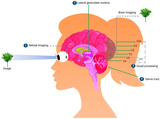
Figure 1. In the human visual system, “Retinal imaging” (①) is the first stage for processing an image when it enters the eye’s visual field. The retina transmits pixels, shade, and color through the chiasma to the brain stem’s “lateral geniculate nucleus” (LGN) (②). Visual information is further processed here, important visual information is extracted, useless information is discarded, and critical visual information is processed and transmitted to the primary “visual cortex” (③) V1 and then via V2 and V3 to V4, V5 (MT area), and higher brain areas [1][2][48,49]. The visual flow is then processed layer by layer and transmitted to more areas on the surface of the brain, where the brain identifies the object in the eye’s view [3][50]. The “nerve tract” (④) runs through the brain and spinal cord throughout the body, and its main function is to control body movement [4][51].
In nature, the human eye is not the strongest. Animals such as eagles and octopi have eyes more developed than those of humans. What makes humans the most powerful animals in nature? This is the fact that the human brain is highly powerful [5][6][7][52,53,54]. To understand the deeper principles of the human visual processing system, let' us examine the principles of human visual pathways. As shown in Figure 2, the human brain is divided into the left and right brains. The left brain is responsible for the visual field information of the right eye, while the right brain is responsible for the visual field of the left eye. Light waves are projected onto the retina at the bottom of the eyeball through the pupil, lens, and vitreous of the human eye, thereby forming a light path for vision. The optic nerve carries information from both the eyes to the suprachiasmatic nucleus. It then passes to the lateral geniculate nucleus (LGN), where visual information is broken down, twisted, assembled, packaged, and transmitted via optic radiation to the primary visual cortex V1, which detects information regarding the image’s orientation, color, the direction of motion, and position in the field of vision. The image information is then projected onto the ventral stream, also known as the “what” pathway, and the dorsal stream, also known as the “where “ pathway, which is responsible for object recognition. The dorsal pathway is responsible for processing information such as movement and spatial orientation [8][9][10][11][55,56,57,58].
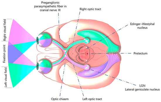
Figure 2.
Human visual pathways. Copyright citation: This image is licensed by Eduards Normaals.
The superior colliculus controls the unconscious eye and head movements, automatically aiming the eye at the target of interest in the field of vision and making it shoot into the fovea of the retina of the human eye. This area contains approximately 10 percent of the neurons in the human brain and is the primary area for visual projection in mammals and vertebrates. The anterior tectum controls iris activity to regulate pupil size [12][59]. As shown in Figure 2, light information first enters the Edinger–Westphal nucleus through the anterior tectum. The Edinger–Westphal nucleus has the following functions: (i) controlling the ciliary muscle to regulate the shape of the lens; (ii) controlling the ciliary ganglion; and (iii) regulating pupil size via cranial nerve III [13][60].
Borra conducted anatomical experiments and studies on visual control in the rhesus-monkey brain. Stimuli and scans of the visual cortex of awake rhesus-monkey brains revealed that humans and nonhuman primates have similar visual control systems. However, the human brain is more complicated. Therefore, the similarity between the brain visual systems of rhesus monkeys and humans provides an important basis for humans to understand the principles of their eye movements and conduct experimental research [14][15][61,62]. The visual cortex regions of the human and macaque brains are depicted in Figure 3.
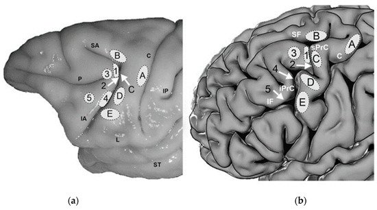
Figure 3. A region at the junction of the prefrontal and premotor cortex in (a) rhesus monkeys and primates, (b) human brain. Known as the anterior field of vision (FEF), it is primarily involved in controlling eye-movement behavior and spatial attention. Humans have at least two types of forwarding fields of vision. After comparing the letters in the visual nerve regions of the human brain and monkey brain, it was found that the monkey visual cortex corresponds to the human visual cortex; and the principles of spatial attention, dynamic vision control, and attention orientation control are very similar [16][63]. The letters A, B, C, D, and E in the figure represent the visual cortex regions of the human and monkey brains. The image has been licensed by ELSEVIER.
Most mammals have two eyes that allow them to perform complex movements. Each eye is coordinated by six extraocular muscles according to [17][64]: the inner, outer, upper, and lower rectus muscles and the upper and lower oblique muscles. These muscles coordinate movements, allowing the eye to move freely in all directions and to change the line of sight as needed. The function of the internal and external rectus muscles is to turn the eyes inward and outward, respectively. Because the superior and inferior rectus muscles have an angle of 23° with the optic axis and the superior and inferior oblique muscles have an angle of 51° with the optic axis, they play a secondary role in addition to their main roles. The main function of the superior rectus muscle is upward rotation, whereas its secondary function is internal rotation.
The main function of the inferior rectus muscle is downward rotation, and its secondary functions are internal and external rotation. The main function of the superior oblique is internal rotation, and the secondary functions are external and downward rotation. The main function of the inferior oblique is external rotation, and the secondary functions are external and upward rotation. In addition, the movement of the extraocular muscles is restricted to prevent the eyes from going beyond the range of motion, and mutually restricted extraocular muscles are called antagonistic muscles. Synergistic muscles are cooperative in one direction and antagonistic in another. Movement of the eyeball in all directions requires fine coordination of the external eye muscles, and no eye muscle activity is isolated. Regardless of the direction of the eye movement, 12 extraocular muscles are involved. When a certain extraocular muscle contracts, its synergistic, antagonistic, and partner muscles must act simultaneously and equally to ensure that the image is accurately projected onto the corresponding parts of the retinas of the two eyes [18][19][65,66].
The extraocular muscle is driven and controlled by the cranial nerve, which directs the muscle to contract or relax. Eye movements occur when one part of the extraocular muscle contracts and the other relaxes. The motion features of the human eyes mainly include conjugate movement, vergence or disjunctive movement, vestibulo-ocular reflex (VOR), and optokinetic reflex (OKR) [16][63]. Specifically, the human eye also exhibits the following motion characteristics [20][21][22][23][24][25][26][67,68,69,70,71,72,73]. The saccade, the most common feature, is a movement occurring rapidly and in parallel from one fixation point to another during which the human eye freely observes its surroundings, lasting between 10 and 80 ms. Mainly used by the human eye to actively adjust the direction of gaze, large saccades require head and neck movement. Smooth pursuit is the movement of the eye tracking a moving object, which is characterized by smooth tracking of the target. The angular velocity of the eye movement corresponds to the velocity of the moving object when the eye is observing a low-speed object. The adult eye can follow objects with 100% smoothness. When the target angular velocity is greater than 150°/s, the human eye cannot track the target. When the target object appears in the visual field of the human eye and begins to move at a high speed, the human eye tracks the target. The eyes have rhythmic horizontal nystagmus and maintain the same direction as the movement of the object. When the direction and speed of the human eye are consistent with those of the object, the human eye can clearly see the object. For example, one can sit in a fast-moving car and see the scenery outside the window. When the head moves, the eyes move in the opposite direction; thus, the image maintains steady reflective movement on the retina. For example, when the head moves to the right, the eyes move to the left, and vice versa. The primary function of OVR is motion stabilization, which is characterized by the coordination of head movements to obtain a more stable image. OVR has been used in camera anti-shake mechanisms. Conjugate motion is the simultaneous movement of the eyes in the same direction so that diplopia does not occur. Its characteristics can be divided into saccades and smooth tracking motions. When a target approaches, the visual axes of the two eyes intersect inward, presenting a convergent motion state, whereas when the target moves far away, the visual axis of the two eyes diverges outward, presenting a state of divergent motion. The hold time of the convergent motion is approximately 180 ms, and that of the divergent motion is approximately 200 ms. The process of keeping one’s eyes on the target for a long time is called fixation. The eyeball quivers during the gaze, keeping the image refreshed and achieving a clearer visual effect. The eyes of most mammals vibrate slightly when focusing on stationary objects. The mean amplitude of a saccade is 0.2 ms (millisecond), which is half of the cone cell diameter. The vibration frequency reaches 80–100 Hz. Movement can produce light and light effects, and its purpose is to keep the visual center and visual cells in a state of excitement and maintain a high degree of visual sensitivity.
When humanswe observe a scene through theiour eyes, theiour eyes do not perform a single motion feature but combine the various eye movement features mentioned above to achieve high-definition, wide-dynamic-range, high-speed, and flexible-target visual tracking. Making machines have the same advantages as humans and animals is the research goal of future robots.
2. Differences and Similarities between Human Vision and Bionic Vision
The human visual system operates on a network of interconnected cortical cells and organic neurons. In contrast, a bionic vision system runs on an electronic chip composed of transistors, mainly through a camera with CMOS and CCD sensors, image acquisition, and sending the image to a special image-processing system to obtain the form of the recorded target information and encode it according to pixel, brightness, color, and other information. The image-processing system performs various operations on these codes to extract the characteristics of the target. Through specific equipment, it simulates the visual ability of human beings to make corresponding decisions or execute on these decisions [27][74]. Figure 4 depicts the human vision processing and representative machine vision processing processes.
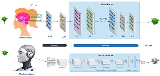
Figure 4.
Human vision processing and Representative machine vision processing processes.
Human visual path: RGB light wave → cornea → pupil → lens (light refraction) → vitreous (supporting and fixing the eyeball) → retina (forming object image) → optic nerve (conducting visual information) → lateral geniculate body → optic chiasma → primary visual cortex V1 → other visual cortices V2, V3, V4, V5, etc. → the brain understands and executes → other nerves are innervated to perform corresponding actions.
Bionic vision path: RGB color image → image sensor (image coding) → image processing (image decoding) → image operator (image gray processing, image correction, image segmentation, image recognition, etc.) → output results and execution.
The information in the brain moves in multiple directions. Light signals move from the retina to the inferior temporal cortex, where they are transmitted to V1, V2, and other layers of the visual cortex. Simultaneously, each layer provides feedback on the previous layer. In each layer, neurons interact with each other and communicate information, and all interactions and connections essentially help the brain to fill in gaps in visual input and make inferences when information is incomplete.
The machine mainly converts the image into a digital electrical signal through the image acquisition device and transmits it to the image processor. There are plenty of image processors, and the most common one is GPU. With professional AI computing requirements, ASIC (application-specific integrated circuit) emerged. ASIC performs better than CPU, GPU, and other chips, with higher processing speed and lower power consumption. However, ASIC is very expensive to produce [28][29][30][75,76,77]. For example, Google has developed an ASIC-based TPU that is dedicated to accelerating the computing power of deep neural networks [31][78]. In addition, there are also NPU, DPU, etc. [32][33][34][79,80,81]. FPGA is a processor for developers to customize; usually, an image processor integrates machine vision perception and recognition algorithms. There are diverse algorithm models, such as CNN, RNN, R-CNN, Fast R-CNN, Mask R-CNN, YOLO, and SSD [35][36][37][82,83,84], which vary in terms of performance and processing speed. The most classical and widely used algorithm is the convolutional neural network (CNN) algorithm. Specifically, the convolutional layer first extracts the initial features, then the pooling layer extracts the main features, and finally, the fully connected layer summarizes all features to provide a classifier for prediction and recognition. The convolutional and pooling layers are sufficient to identify the complex image contents, such as faces and car license plates. Data in artificial neural networks often move in a one-way manner. CNN is a “feedforward network”, where the information moves step by step from the input layer to the next layer and the output layer. This network mainly makes use of the visual center of human beings, and its disadvantage is that it receives all continuous sequences. Utilizing CNN is equivalent to separating the front and the back connections. Therefore, the recursive neural network (RNN) that is dedicated to processing sequences emerges. In addition to entering the current information, each neuron has previously generated memory information that retained the sequence-dependent type. In the visual cortex, the information moves in multiple directions. The brain neurons are equipped with “complex temporal integration capabilities that are lacking in existing networks” [38][85]. Beyond CNN, Geoffrey Hinton et al. have been developing the “capsule network”. Similar to the neuronal pathway, this new network is much better than the convolutional networks at identifying overlapping numbers [39][86].
In general, a high-performance image-processor platform is required for a high-precision image recognition algorithm. Although the great leaps in the fields of GPU rendering, hardware architecture, and computer graphics have enabled realistic scene and object rendering, these methods are demanding in terms of both time and computational resources [40][87]. As most robots are mobile, most bionic vision systems adopt a mobile terminal processor, and their performance cannot match a graphics server. For example, one of the features of the iCub robot is that it is equipped with a stereo camera rig in the head and a 320 × 240 resolution color camera in each eye. This setup consists of three actuated DoF in the neck of the robot to grant the roll, pitch, and yaw capabilities to the head, as well as three actuated DoF to model the oculomotor system of a human being (tilt, version, and vergence) [41][88]. Furthermore, F. Bottarel [42][89] made a comparison of the Mask R-CNN and Faster R-CNN algorithms using the bionic vision hardware of the iCub robot [43][90] and discovered that Mask R-CNN is superior to Faster R-CNN. Currently, many computer vision algorithm workers are constantly optimizing and compressing their algorithms to minimize the loss of accuracy and match the processing capacity of the end-load system.
Therefore, compared with machine vision, not only is the human vision system processing power great, but the human visual system also can dynamically modify the attention sensitivity in response to various targets. However, this flexibility is difficult to achieve in computer vision systems. Currently, computer vision systems are mostly intended for single purposes such as object classification, object placement, image region partitioning by object, image content description, and fresh image production. There is still a gap between the high-level architecture of artificial neural networks and the functioning of the human visual brain [44][93].
Perception and recognition technology is the most critical technology for intelligent robots [45][46][94,95]. Perception technology based on visual sensors has been the most researched technology [47][96]. People use a variety of computer-vision-based methods to build a visual system with an initial “vision” function. However, the functions of the “eyes” of intelligent robots are still relatively low-level, especially in terms of binocular coordination, tracking of sudden changes or unknown moving targets, the contradiction between a large field of view and accurate tracking, and compensation for vision deviation caused by vibration. After millions of years of evolution, biological vision has developed and perfected the ability to adapt to internal and external environments. According to the different functional performances and applications of simulated biological vision, the research on visual bionics can be summarized into two aspects: one is research from the perspective of visual perception and cognition. The second is research from the perspective of eye movement and sight control. The former mainly studies the visual perception mechanism model, information feature extraction and processing mechanisms, and target search in complex scenes. The latter, based on the eye-movement control mechanism of humans and other primates, attempts to build the “eyes” of intelligent robots to achieve a variety of excellent biological eye functions [48][49][50][97,98,99].
3. Advantages and Disadvantages of Robot Bionic Vision
Compared to human vision, robot bionic vision has the following advantages [51][52][53][54][100,101,102,103]:
-
High accuracy: Human vision is 64 gray-levels, and the resolution of small targets is low [55][104]. Machine vision can identify significantly more gray levels and resolve micron-scale targets. Human visual adaptability is considerably strong and can identify a target in a complex and changing environment. However, color identification is easily influenced by a person’s psychology. Humans cannot identify color quantitatively, and their gray-level identification can also be considered poor, normally seeing only 64 grayscale levels. Their ability to resolve and identify tiny objects is weak.
-
Fast: According to Potter [56][105], the human brain can process images seen by the human eye within 13 ms, which is converted into approximately 75 frames per second. The results extend beyond the 100 ms recognized in earlier studies [57][106]. Bionic vision can use a 1000 frames per second frame rate or higher to realize rapid recognition in high-speed image movement, which is impossible for human beings.
-
High stability: Bionic vision detection equipment does not have fatigue problems, and there are no emotional fluctuations. Bionic vision is carefully executed according to the algorithm and requirements every time with high efficiency and stability. However, for large volumes of image detection or in the cases of high-speed or small-object detection, the human eye performs poorly. There is a relatively high rate of missed detections owing to fatigue or inability.
-
Information integration and retention: The amount of information obtained by bionic vision is comprehensive and traceable, and the relevant information can be easily retained and integrated.
Robot bionic vision also has disadvantages such as a low level of intelligence, for it is unable to make subjective judgments, has poor adaptability, and has large initial investment cost. Furthermore, by incorporating non-visible light filling and photosensitive technology, bionic vision achieves night vision beyond the sensitivity range of the human eye. Bionic vision is not affected by severe environments, is not fatigued, can operate frequently, and has a low cost of continuous use. It simply requires an investment at the beginning to set up. Continued operation incurs only energy and maintenance costs.
4. The Development Process of Bionic Vision
If light from a source object is shone into a dark space through a small hole, an inverted image of the object can be projected onto a screen, such as the opposite wall. This phenomenon is called ”pinhole imaging”. In 1839, Daguerre of France invented the camera [58][107], and thus began the era of optical imaging technology. The stereo prism was invented in 1838. By 1880, Miguel, a handmade camera manufacturer in London, UK, had produced dry stereo cameras. At that time, people had early stereo vision devices, but these devices could only store images in films. In 1969, Willard S. Boyle and George E. Smith of Bell Laboratories invented a charge-coupled device (CCD), which is an important component of the camera [59][108]. A CCD is a photosensitive semiconductor. They can convert optical images into electrical signals. A tiny photosensitive material implanted in the CCD is called a pixel. The more pixels a CCD contains, the higher its picture resolution. However, the function of the CCD is similar to that of a film: it converts the optical signal into a charge signal. The current signal is amplified and converted into a digital signal to realize the acquisition, storage, transmission, processing, and reproduction of the image. In 1975, camera manufacturer Kodak invented the world’s first digital camera using photosensitive CCD elements six years earlier than Sony [60][109]. At that time, the camera had 10,000 pixels, but the digital camera was still black and white. Surprisingly, in 2000, Sharp’s J-SH04 mobile phone was equipped with a 110,000 pixel micro CCD image sensor. Thus began the age of phone cameras. People can now carry cameras in their pockets [61][62][110,111]. The development of vision equipment and bionic vision technology in Figure 5.
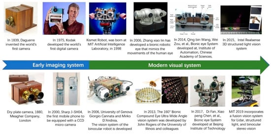
Figure 5.
The development of vision equipment and bionic vision technology.
Early image systems laid a solid foundation for modern vision systems and the future development of imaging techniques and processing. By consulting and searching through vast and relevant technical literature, it was found that the current industry mainly includes two technical schools: the bionic binocular vision system and the bionic compound eye vision system. The main research scholars are B. Scassellati, G. Canata, Z. Wei, Z. Xiaolin, and W. Xinhua.
According to WHO statistics, 285 million people worldwide are visually impaired. Of these, 39 million are classified as blind [63][112]. Scientists have been working to develop bionic eye devices that can restore vision. Arthur Lowery has studied this topic for several decades. His team successfully developed a bionic vision system called Gennaris [64][113]. Because the optic nerve of a blind person is damaged, signals from the retina cannot be transmitted to the “visual center” of the brain. The Gennaris bionic vision system can bypass damaged optic nerves. The system includes a “helmet” with a camera, wireless transmitter, processor, and 9 × 9 mm patch implanted into the brain. The camera on the helmet sends captured images to the visual processor, where they are processed into useful information. The processed data are wirelessly transmitted to the patch implanted into the brain and then converted into electrical pulses. Through microelectrode stimulation, images are generated in the visual cortex of the brain. Professor Fan Zhuo of the Hong Kong University of Science and Technology and his team successfully developed a bionic eye based on the hemispherical retina of a perovskite nanowire array. This bionic eye can achieve a high level of image resolution and is expected to be used in robots and scientific instruments [65][66][114,115].
In 1998, the Artificial Intelligence Laboratory at MIT created a vision system for the Kismet robot. However, at that time, robot vision could only achieve a considerably simple blinking function and image acquisition. Since then, significant progress has been made in binocular robot vision systems. In 2006, Cannata [67][33] from the University of Genoa designed a binocular robot eye by imitating the human eye and adding a simple eye-movement algorithm. At that time, the eyes of the robot could move rigidly up, down, left, and right. Subsequently, it was recognized by the Italian Institute of Technology (IIT) and applied to the iCub robot after continuous technical iterations [68][116]. In 2000, Honda developed the ASIMO robot [69][117]. Currently, the latest generation of ASIMO is equipped with binocular vision devices [70][118]. Thus far, most robots, including HRP-4C [71][119] and the robots being developed at Boston Dynamics, combine 3D LiDAR with a variety of recognition technologies to improve the reliability of robot vision [72][120]. Robots that have bionic vision in Figure 6.
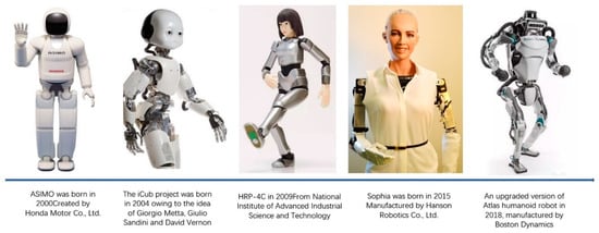
Figure 6.
Robots that have bionic vision. Copyright: Robot licensed by Maximalfocus US-L.
Machine vision processing technology is also being developed. As early as the 1980s, the Artificial Intelligence Laboratory at MIT began conducting relevant research. In the 1990s, bionic vision technology began to perform feature analysis and image extraction. In June 2000, after the first open-source version of OpenCV Alpha 3 was released [73][121], with the emergence of CNN, RNN, YOLO, ImageNet, and other technologies, bionic vision entered a stage of rapid development using artificial intelligence [74][75][122,123].
5. Common Bionic Vision Techniques
Bionic vision technology uses a camera equipped with a CCD or CMOS image sensor to obtain the depth information for an object or space. It is the most used technology in intelligent devices such as robot vision systems and automatic vehicle driving. For example, NASA carried a binocular vision system on the Perseverance Mars Rover in 2020 [76][124]. In 2021, the Astronomy-1 Lunar Rover developed by China Aerospace also used a binocular terrain-navigation vision system [77][125]. At present, the mainstream technologies of binocular bionic vision include stereo vision, structured light, time of flight (TOF), etc. [47][78][79][80][81][82][83][84][85][86][87][88][89][90][91][92][96,126,127,128,129,130,131,132,133,134,135,136,137,138,139,140].
5.1. Binocular Stereo Vision
This technology was first introduced in the mid-1960s. It is a method for obtaining three-dimensional geometric information about an object by calculating the position deviation between the corresponding points on its images based on the parallax principle and using imaging equipment to obtain two images of the measured object from different positions. A binocular camera does not actively emit light; therefore, it is called a “passive depth camera”. At present, it is used in the field of scientific research because it does not require a transmitter and receiver of structured light and TOF; thus, the hardware cost is low. Because it depends on natural light, it can be used indoors and outdoors, but strong and dark light can affect the quality of the image or the depth measurement of the object. This is a known disadvantage of the binocular camera. For example, for a solid color wall, because the binocular camera matches the image according to visual characteristics, a single background color causes a matching failure, and the visual matching algorithm is complex. The main representative products include Leap Motion and robotic eyes.
5.2. Structured Light
The basic principle of this technology is that the main hardware includes a projector and camera. The projector actively emits (therefore called active measurement) invisible infrared light onto the surface of the measured object, then captures pictures of the object through one or more cameras, collects structured light images, sends the data to a calculation unit, and calculates and obtains position and depth information through the triangulation principle to realize 3D reconstruction. Therefore, structured light is used to determine the structure of the object. There are many projection patterns, such as the sinusoidal fringe phase-shift method, binary-coded gray code, and phase-shift method + gray code. The advantages of this method include mature technology, low power consumption, low cost, active projection, suitability for weak lighting, high precision within a close range (within 1 m), and millimeter-level accuracy. A major disadvantage is poor long-distance accuracy. With the extension of the distance, the projection pattern becomes larger, and the accuracy worsens. It is not suitable for strong outdoor light, which can easily interfere with projection light. Representative products include Kinect, Primesense, and Intel Realsense.
5.3. TOF (Time of Flight)
This technology is a 3D imaging technology that has been applied to mobile phone cameras since 2018. Its principle is to emit continuous pulsed infrared light of a specific wavelength onto the target and then receive the optical signal returned by the target object via a specific sensor. The round-trip flight time or phase difference of the light is calculated to obtain depth information for the target object. The TOF lens is mainly composed of a light-emitting unit, optical lens, and image sensor. The TOF performs well in terms of close measurements and recognition. Its recognition distance can reach 0.4 m to 5 m. Unlike binocular cameras and structured light, which require algorithmic processing to output 3D data, TOF can directly output the 3D data of the target object. Although structured light technology is best suited for static scenes, TOF is more suitable for dynamic scenes. The main disadvantage is that its accuracy is poor, and it is difficult to achieve millimeter-level accuracy. Because of its requirements for time measurement equipment, it is not suitable for short-range (within 1 m) applications compared to structured light, which performs well for short- and high-precision applications. It cannot operate normally under strong light interference. Representative products that use this technology include TI-Opt and ST-Vl53.
It can be seen that Table 13 presents the following advantages and disadvantages: (1) monocular technology has a low cost and high speed, but its accuracy is limited, and it is unable to obtain depth information; (2) binocular ranging is the closest to human vision, without a passive light source, and the working efficiency is acceptable, but it is difficult to realize a high-precision algorithm, and it is easily disturbed by environmental factors; (3) a structured light scheme is more suitable for short-range measurements but has high power consumption; and (4) TOF and structured light have the same disadvantages. The miniaturization of the sensor has a significant impact on resolution. (5) Although LiDAR has high precision, even for long distances, its resolution is low. The machine vision measurement technologies have both advantages and disadvantages. Therefore, in recent years, many well-known robot manufacturers have adopted technology integration to improve the accuracy and practicality of robotic vision. For example, Atlas [93][141] of Boston Power adopts a vision combination of binocular and structured light + LiDAR.
Table 13.
Performance comparison table of mainstream visual technology.
| Technology Category | Monocular Vision | Binocular Stereo Vision | Structured Light | TOF | Optical Laser Radar |
|---|---|---|---|---|---|
| Product pictures |  |
 |
 |
 |
 |
| Technology principle |  |
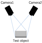 |
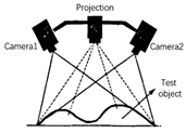 |
 |
 |
| Principle of work | Single camera | Dual camera | Camera and infrared projection patterns | Infrared reflection time difference | Time difference of laser pulse reflection |
| Response time | Fast | Medium | Slow | Medium | Medium |
| Weak light | Weak | Weak | Good | Good | Good |
| Bright light | Good | Good | Weak | Medium | Medium |
| Identification precision | Low | Low | Medium | Low | Medium |
| Resolving capability | High | High | Medium | Low | Low |
| Identification distance | Medium | Medium | Very short | Short | Far |
| Operation difficulty | Low | High | Medium | Low | High |
| Cost | Low | Medium | High | Medium | High |
| Power consumption | Low | Low | Medium | Low | High |
| Disadvantages | Low recognition accuracy, poor dark light | Dark light features are not obvious | High requirements for ambient light, short recognition distance | Low resolution, short recognition distance, limited by light intensity | Cloudy and rainy days, fog, and other weather interference have effects |
| Representative company | Cognex, Honda, Keyence | LeapMoTion, iit | Intel, Microsoft, PrimeSense | Intel, TI, ST, Pmd | Velodyne, Boston Dynamics |
Data sources: Official websites of related products and patent databases.
