Your browser does not fully support modern features. Please upgrade for a smoother experience.
Please note this is a comparison between Version 1 by Chiemela Victor Amaechi and Version 2 by Vivi Li.
Diverse forms of offshore oil and gas structures are utilized for a wide range of purposes and in varying water depths. They are designed for unique environments and water depths around the world. The applications of these offshore structures require different activities for proper equipment selection, design of platform types, and drilling/production methods. There are advances made in ocean engineering which include a variety of innovative offshore structure designs, ranging from fixed platforms to floating platforms. Some of these structures include the deep-water semisubmersible platforms, jack-up rigs, floating offshore wind turbines (FOWTs), FPS (floating production systems) units.
- offshore structure
- offshore platform
- fixed platform
- floating platform
- oil and gas platform
- production platform
- drilling platform rig
- coastal structure
- marine structure
- offshore facilities and subsea systems
- review
- offshore
1. Introduction
With the increase in the need for more energy sources, fossil fuel has recently had huge competition as a non-renewable energy source with other renewable energy sources. However, some of these newer platforms have extended technologies that stem from the existing offshore platforms used in oil and gas exploration. Currently, there are advances made in ocean engineering which include a variety of innovative offshore structure designs, ranging from fixed platforms to floating platforms [1][2][3][4][5][1,2,3,4,5]. Some of these structures include the deep-water semisubmersible platforms, jack-up rigs, floating offshore wind turbines (FOWTs), FPS (floating production systems) units, floating production storage and offloading (FPSO) units, FSO (floating storage and offloading) units, FSU (floating storage units), FPU (floating production units), FDPSO (floating drilling production storage and offloading), MODU (mobile offshore production unit) and FLNG (floating liquid natural gas vessel) [6][7][8][9][10][6,7,8,9,10]. However, there are other applications for offshore platforms, such as dynamic positioning, exploratory activities, drilling/production, navigation, (un)loading ships, fluid transport, and bridge support [11][12][13][14][15][16][11,12,13,14,15,16]. Offshore petroleum structures are utilized for a wide range of purposes and in a wide range of sea depths and environments around the world, hence they need supporting attachments such as drilling marine risers [17][18][19][20][21][22][23][17,18,19,20,21,22,23], composite production risers [24][25][26][27][28][29][30][24,25,26,27,28,29,30], marine hoses [31][32][33][34][35][36][37][38][39][40][31,32,33,34,35,36,37,38,39,40] and mooring lines [41][42][43][44][45][46][47][48][49][41,42,43,44,45,46,47,48,49].
Offshore platforms could be used as artificial reefs for many years, as they have also been used in a variety of aquatic environments. As a result, their design and upkeep are extremely difficult. Hence, it is pertinent that the design and maintenance of offshore structures are well considered, to prevent early decommissioning, high risks of corrosion, oil spillage, and other irreversible environmental damages. The applications of these offshore structures require different activities for proper equipment selection [50][51][52][53][54][55][56][57][50,51,52,53,54,55,56,57], design of platform types [58][59][60][61][62][63][64][58,59,60,61,62,63,64], engineering management of well bores [65][66][67][68][69][70][71][72][73][65,66,67,68,69,70,71,72,73] and other drilling/production methods [74][75][76][77][78][79][80][74,75,76,77,78,79,80]. Offshore oil production is one of the most visible of these applications, and it provides a significant task to the product designer or offshore engineer [81][82][83][81,82,83]. The design considerations include environmental loadings [84][85][86][87][88][84,85,86,87,88], hydrodynamics [89][90][91][92][93][94][95][96][89,90,91,92,93,94,95,96], hydroelasticity [97], corrosion [98], failure analysis [99], ocean wave mechanics [100][101][102][103][104][105][106][107][108][100,101,102,103,104,105,106,107,108], fluid content loadings [109][110][111][112][113][114][115][109,110,111,112,113,114,115], fatigue limits [116][117][118][119][120][116,117,118,119,120], reliability [121][122][123][124][125][126][127][128][121,122,123,124,125,126,127,128], etc. Therefore, the designer must ensure that there is safety, stability, high fatigue resistance with a long service life. The design with that is safe, but cost must be considered; hence the designer should make it economical for the client. Generally, these offshore assets must operate safely for at least twenty-five (25) years (depending on the purpose of the offshore structure), because they are exposed to extremely severe marine environments and varying sea depths. Hence the designs are conducted by using peak loads provided during the platform design life by the hurricane wind and waves. Environmental conditions are also important in designing different offshore structures [129][130][131][132][133][134][135][129,130,131,132,133,134,135]. Also, there are more developments made in oceanography and environmental sciences that reflect in different designs of offshore structures [136][137][138][139][140][141][142][136,137,138,139,140,141,142]. The fatigue loads caused by waves over the platform’s lifetime and platform motion are all critical design issues considered in standards elaboration such as the American Petroleum Institute (API) [136][137][138][139][140][141][136,137,138,139,140,141], and Det Norske Veritas (DNV) [142][143][144][145][146][147][148][149][150][151][152][142,143,144,145,146,147,148,149,150,151,152]. Over time, these developed API standards have been revised to include hurricane conditions in the Gulf of Mexico (GoM), adaptable in other seas [153][154][155][156][157][153,154,155,156,157]. Strong currents can sometimes hit the platforms, putting strain on the entire system’s integrity. Another challenge that oil corporations face is the project scheduling involving the length of time for the design and construction of these offshore assets. Furthermore, the size of these offshore structures is a consideration in designing their stability and hydrodynamics.
Another consideration factored in the design is the material density. Most offshore platforms are fabricated in shipyards using massive steel, or in-situ using concrete, as seen in gravity-based structures. These offshore structures- both fixed and floating structures are mostly used for energy generation or oil production. Offshore constructions are meant to be installed thousands of kilometers from shorelines in the open sea, lakes, gulfs, and other bodies of water. Steel, reinforced concrete, or a combination of the two, may be used to construct these buildings. Most oil and gas platforms are produced from a variety of steel grades. These range from mild steel to high-strength steel, despite some earlier structures being made of reinforced concrete called the Concrete Gravity Based Structures (CGBS). Steel platforms come in different sizes and shapes, based on their intended function and, most importantly, the water depth in which they will operate [29][30][31][32][33][34][29,30,31,32,33,34]. However, proper failure analysis and reliability studies have to be carried out on these offshore structures. Offshore platforms are extremely hefty and among the world’s tallest man-made structures. Floating structures have been classified, based on water depths, such as shallow water (91–120 m and lesser than 91 m), mid water (121–305 m), deep water (306–1219.50 m) and ultra-deep water (1220.50–2285.69 m and greater than 2285.69 m). These offshore structures are available at different locations, from Offshore West Africa (OWA) to the Baltic Sea, the Persian Sea, the North Sea (NS) and the Gulf of Mexico (GoM). These seas have different oil companies and energy operators involved in offshore operations across different geographical locations. Presently, different oil companies have high impact oil wells as seen in some operators of various offshore platforms.
2. Overview of Platform Installations
The historical development of different offshore platforms differ over varying timelines, as seen in designs, inventions and patents. This section presents the historical backgrounds of certain offshore structures, depending on the classification of the structure. In addition, these platform installations have evolved with different standards. In addition, various standard bodies have also evolved in the general design of offshore structures such as the following: API [158][159][160][161][162][163][164][165][166][167][168][169][170][158,159,160,161,162,163,164,165,166,167,168,169,170], DNV [171][172][173][174][175][176][177][178][179][180][181][171,172,173,174,175,176,177,178,179,180,181], Det Norske Veritas and Germanischer Lloyd (DNVGL) [182][183][184][185][186][182,183,184,185,186] the American Bureau of Shipping (ABS) [187][188][189][190][191][192][193][194][195][196][197][198][187,188,189,190,191,192,193,194,195,196,197,198] and International Organization for Standardization (ISO) [199][200][201][202][203][204][205][206][207][208][209][210][211][199,200,201,202,203,204,205,206,207,208,209,210,211]. Historically, most of the earlier offshore constructions had standards as bulletins, and they were developed over time. These standards ensure that the design of the offshore structure, including its attachments (such as the marine risers and the mooring system), as well as different dynamic effects (such as vortex shedding) are specified [212][213][214][215][216][217][218][219][212,213,214,215,216,217,218,219]. Today, there are more standards that are used for the design and analysis of offshore structures, oil and gas exploration, and production and extraction activities [220][221][222][223][224][225][226][227][228][229][230][231][220,221,222,223,224,225,226,227,228,229,230,231]. Table 1 shows an inventory of deep-water offshore platforms in the Gulf of Mexico (GoM).Table 1.
Inventory of deep water platforms in GoM; (Courtesy: BOEM, data retrieved in 2016).
| Platform | Sidetrack Subsea Well | Sidetrack Dry Trees Well | Amount | Subsea Field |
|---|---|---|---|---|
| FPSO | 1 (2) | 2 (0) | 1 | 1 (1) |
| Mobile offshore production units (MOPU) | 6 (13) | -- -- | 1 | -- (2) |
| Semisubmersible | 32 (28) | 22 (16) | 9 | 6 (18) |
| Mini TLP | 17 (17) | 11 (16) | 5 | 1 (6) |
| Tension Leg Platform (TLP) | 51 (60) | 123 (150) | 10 | 8 (14) |
| Single Point Anchor Reservoir (SPAR) | 34 (43) | 133 (129) | 16 | 13 (18) |
| Fixed Platform (FP) | 47 (49) | 630 (449) | 50 | 49 (30) |
| Compliant towers (CT) | 3 (1) | 76 (46) | 3 | 4 (2) |
| AGGREGATE | 191 (213) | 997 (806) | 95 | 82 (91) |
- (a)
-
Jack-up rig or Tender rig for extraction of oil/gas, drilling and templates (jackets) in water depths up to 150 m;
- (b)
-
A semi-submersible drilling rig with a template (jacket) platform for extraction of oil/gas, at sea depths of 150 to 300 m;
- (c)
-
A semi-submersible drilling rig with guyed-tower platforms for oil/gas extraction at depths of 300 to 400 m;
- (d)
-
Semi-submersible drilling rig with tension leg platform or semi-submersible oil/gas extraction platform for water depths of 400 m to 1800 m;
- (e)
-
Drillship rig with tension leg, subsea system, or spar platforms for oil/gas extraction in depths greater than 1800 m;
- (f)
-
Floating production storage and offloading (FPSO) are found operating in water depths ranging from 200 m to more than 3000 m [260] and depending on the environmental condition, they are maintained in position using either a spread or turret mooring system.
2.1. Floating Production Systems
Floating production systems are similar to semi-submersible drilling rigs, but they also include petroleum production equipment in addition to drilling equipment. Ships can potentially be utilized as floating manufacturing platforms. Large, heavy anchors or the dynamic positioning mechanism utilized by drillships can be used to keep the platforms in place. With a floating production system, the wellhead is attached to the seafloor rather than the platform once the drilling is completed. The extracted petroleum is delivered by risers from the wellhead to the semi-submersible platform’s production facilities. These production devices can work in up to 6000 feet of water.2.2. Fixed Offshore Platform Design
Fixed Offshore Platforms such as the template type platforms made of steel are the most often used offshore platforms in the U.S.A.’s Gulf of Mexico, California shorelines, Niger Delta regions of Nigeria, and the Persian Gulf for oil/gas exploration and production [14][83][14,83]. These offshore constructions must be designed and analyzed in compliance with the American Petroleum Institute (API)’s recommendations. There are four different types of fixed offshore platforms, which are conventional fixed platforms, compliant towers, junction platforms and bridged platforms (or complexes, as seen in Figure 14).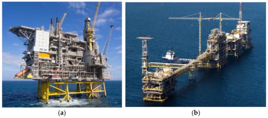 Figure 14. Typical platforms showing (a) conventional jacket platforms and (b) bridged fixed jacket platform on Zuluf oil field in Arabian Gulf, offshore northeast Saudi Arabian coast, with the water depth of about 40 m (Image (b) Courtesy: Saudi Aramco).
2.3. Subsea System
Wells on the sea floor, rather than at the surface, are used in subsea production systems. Petroleum is extracted at the seafloor, similar to a floating production system, and then ‘tied-back’ to an existing production platform. The well can be drilled with a mobile rig, and instead of constructing a production platform for that well, the recovered oil and natural gas can be delivered to a nearby production platform through a riser or even an undersea pipeline. This enables a single strategically located production platform to service a large number of wells across a vast area. Subsea systems can be installed in both shallow waters and deep waters. They are normally utilized at depths of 2100 m (6890 feet) or more, and they can only extract and transfer, not drill. Subsea systems are typically those systems whereby their wells have the wellhead mounted upon the floor of the seabed after drilling operations from the wells, by any of the drilling platforms deployed. Recent advances made in sea systems can be seen in the realization of Statoil’s Subsea Factory [232][233][234][232,233,234], as seen in Figure 25. The targeted ambition for such subsea systems is summarized in Table 2.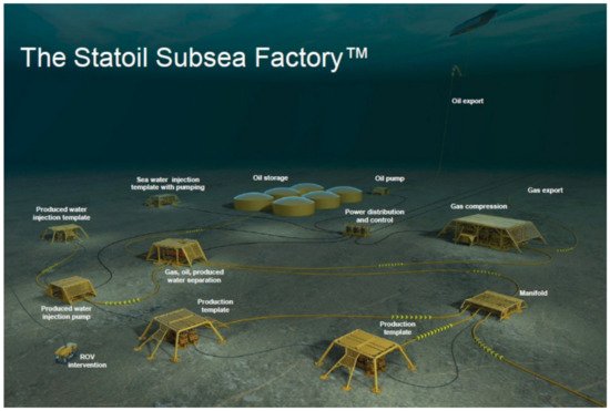 Figure 25.Subsea Production Systems in the Statoil Subsea FactoryTM(Courtesy: Statoil).Table 2.Targeted ambitions for subsea factory.
Key Parameters Heavy Oil Fields Oil Fields Gas/Condensate Fields Colder (heavy/complex fluids) Cold transport Cold flow Sour/Acid gas issues Colder (arctic environment) Harsh environment Under ice Under ice Deep water (deeper environment) 2000 m 3000 m 3000 m Longer power 50 MW 20 MW 100 MW Longer transport 50 km 200 km 250 km 3. Types of Offshore Platforms
Different types of offshore oil rigs and platforms are utilized depending on the water depth and location of the offshore oil/gas field. To drill wells and produce oil and gas, rigs are employed, and platforms are set up in the field. To achieve fossil fuels from oil products, drilling and production activities must be carried out using oil rigs and platforms. Drilling can be used for obtaining natural gas and oil offshore, offshore. Most of the oil deposits are far from the closest mainland, which involves a series of obstacles not encountered when drilling onshore. When drilling at sea (i.e., offshore), the sea floor could be many meters below sea level. As a result, while onshore drilling uses the land as a platform, drilling at sea necessitates the construction of an artificial drilling platform. Since there are different types of offshore structures as depicted in Figure 1 and Figure 36, a comparative analysis of offshore structures is necessary.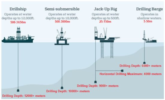 Figure 36.Types of Drilling Rigs.
3.1. Moveable Offshore Drilling Platforms
Offshore drilling rigs/platforms are divided into two categories. The first is a mobile offshore drilling rig that can be moved from one location to another, while the second is a stationary offshore drilling rig. Historically, the first submersible mobile drilling equipment to drill offshore in 1954 was called Mr. Charlie [261]. Over the years, newer developments have been made on moveable platforms. Offshore drilling platforms (and drilling rigs) are those platforms that can be moved from one drilling location to another or even higher application in the industry, as seen in recent leases. A mobile offshore drilling unit (MODU) or unit is a ship that can conduct drilling operations to explore for petrochemical minerals or exploit resources such as liquid or gaseous hydrocarbons, sulfur or salt that are present beneath the seabed. MODU can be jack-up, semi-submersible, barge-type or ship-shaped. For offshore oil and gas drilling, rigid platforms are necessary for drilling operations. They can be moved and retained in place by their own azimuth thrusters with dynamic positioning or hauled into place by a tugboat and moored. A recognized design and operational standard for semi-submersible mobile offshore drilling units (MODU) is the IMO’s MODU Code.3.2. Drilling Barges
Drilling barges are commonly used for shallow-water inland drilling. Drilling barges are massive floating platforms that require tugs to transport from one location to another. Canals, lakes, rivers, marshes, and other bodies of water are frequent areas for this to occur. Drilling barges are only suitable for still, shallow waterways and cannot survive the water movement found in vast open sea conditions. Figure 47 shows some drilling barges used in earlier oil explorations.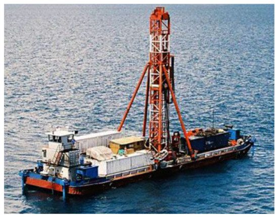 Figure 47.Drilling barge.
3.3. Jackup Drilling Platforms/Rigs
With one difference, jackup rigs are identical to drilling barges. After a jack-up rig is towed to the drilling location, three or four ‘legs’ are lowered until they land on the seafloor. Unlike a floating barge, the working platform can be raised above the water’s surface. Jackup rigs, on the other hand, are only suitable for shallower seas due to the impossibility of extending these legs too far. This rig can only operate in waters up to 500 feet deep. These rigs are usually safer to operate than drilling barges since their working platform is elevated above the sea level [262]. In addition to exploration operations, jack-ups are utilized for drilling operations and wind farms service. Figure 58 shows a Jack-up platform in operation and a labelled projection.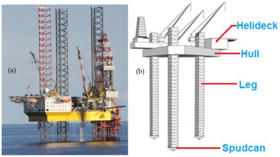 Figure 58.Typical Jack-up Structures showing (a) a jack-up in operation and (b) a labelled projection of the jack-up platform.
3.4. Offshore Wind Turbine Platforms
The global concern about the emission of greenhouse gases has provided a line of research into alternative renewable and clean energy. In this regard, wind power is one of the fastest-growing alternative technologies. However, this technology could help power a clean energy transition only if it can overcome hurdles of cost, design and opposition from fishing. More so, the application of offshore structures in renewable energy has taken more interests on breakwater devices, water energy converters, and wind turbines (such as FOWTs). The scale of wind turbines are larger and more adaptable forms of offshore structures are seen today. Offshore wind turbines may either be fixed-bottom or floating types [263]. The fixed-bottom platform is quite common in off the coast of Denmark, consisting of 91 wind turbines [264]. By design, offshore wind turbines, which are anchored to the seabed with monopile or jacket foundations, can only operate in waters less than 50 m deep. This eliminates sites with the greatest winds and, in many cases, easy access to large markets. However, there are exceptions as the application of Fixed-bottom wind turbines is more economical as it operates in shallow water depths of 50 or 60 m [265]. On the other hand, the floating wind turbines are anchored to the seabed using mooring lines, thus, are suitable for deeper water locations and areas with the soft seabed. Floating wind turbines have been used in water depths of up to 700 m [264][265][264,265]. Different concepts have been identified in on FOWTs projects with different platform types. The projects include DeepCWind, HyWind, WindFloat, NRMI, DTU and MARINTEK wind turbines. The ability to install FOWTs in deeper waters has an open huge amount of the oceans for the generation of renewable wind power. Table 3 shows some existing wind turbines with details.Table 3.List of some offshore wind farms by capacity.Name Installation Year Diameter Tower Height Capacity Status Hornsea 2 2002 167 m 190 m 1396 MW Active Burbo Bank Extension 2017 164 m 113 m 800 MW Active Westermost Rough 2014 154 m 102 m 600 MW Active Anholt 2012 120 m 82 m 360 MW Active Horns Rev 2 2009 93 m 68 m 230 MW Active Nysted 2003 82.4 m 69 m 230 MW Active Middelgrund 2000 76 m 64 m 200 MW Active Vindeby 1991 35 m 35 m 4.95 MW Inactive Although, the floating wind energy is still in its early stage of utilization, close to 80% of the wind power potential is found in deeper water. However, only about 80 megawatts of a total of about 32 GW (0.25%) of the installed offshore wind capacity is from floating wind turbines [265]. This narrative may change in the near future with the US government under USA’s President Joe Biden pledging to build more than 30 GW of offshore wind turbines by the year 2030, worth more than $100 m [265]. Hence, this might bring the assertions of the National Renewable Energy Laboratory (NREL) to reality, which suggests that the floating turbine projects could achieve cost parity with the fixed turbines by the year 2030.By classification, there are four main types of floating platforms, namely the spar-buoy, the tension leg platform, the semi-submersible and the Pontoon-type (Barge-type) floating wind turbines. However, there are other types and design concepts because these are the most common platform already installed and adapted for various planned projects, such as the Semi-submersible platforms which are expected to be used in about 50% to 75% of projects. Figure 69 shows four (4) types of offshore wind turbines.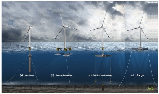 Figure 69. Different types of offshore wind turbines, showing (a) the spar-buoy, (b) the tension leg platform, (c) the semi-submersible and (d) the Pontoon-type (Barge-type) floating wind turbines (Original Illustration by Josh Bauer of NREL, Courtesy: NREL and DNV; Image adapted with permission from NREL and DNV, by Author 1—C.V.A.).
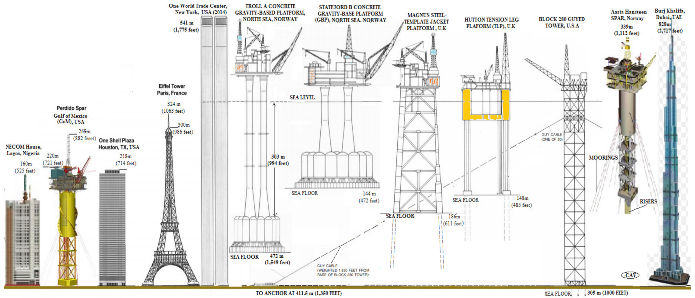 Figure A1. Offshore oil platforms compared to tallest building structures [Credit: Author 1—C.V.A.].