Your browser does not fully support modern features. Please upgrade for a smoother experience.
Please note this is a comparison between Version 2 by Dean Liu and Version 1 by Yavuz Nuri Ertas.
Cochlear implants are neural implant devices that aim to restore hearing in patients with severe sensorineural hearing impairment.
- cochlear implant
- electrode
- spiral ganglion cells
- cochlea
1. Electrode Materials
Electrode materials used for neural stimulation have varied for many years. Biocompatibility, high charge capacitance, high conductivity, and stability are the main qualities desired in CI electrode materials. The most popular alloy materials for CI electrodes are titanium-nitrite, titanium (Ti)-Ir, Ti-tantalum, iridium-oxide, and Pt-Ir [32][1]. In addition, although rare, polymer-coated metal electrodes are among the studied materials. However, the development of cochlear implant electrodes continues in electrode arrays. The main goal of this technological development is to produce an electrode array that is close to the spiral ganglion cells and can perfectly be wrapped around the modiolus, because the electrode in the cochlea should be able to embrace the modiolus to reduce the distance between the targeted spiral ganglion cells and reduce the power consumption and channel interference [33,34,35,36][2][3][4][5]. Here, minimizing channel interference can provide users with a better hearing experience. Additionally, softer and more flexible electrode arrays are required to reduce the insertion trauma of the electrode array and postoperative fibrous tissue formation [37][6]. A hydrogel-based electrode array that can be bent-flexible when exposed to a saline solution (simulating the intracochlear fluid perilymph) was fabricated [38][7]. Here, a reliable hydrogel-driven self-bending CI electrode array was realized with a dummy electrode carrier made of silicon rubber and carbon nanotubes. Trauma during the electrode placement can cause permanent hearing damage. The localized administration of steroid drugs is important to minimize hearing damage. An electrode array consisting of a microfabricated flexible electrode array and a three-dimensional (3D) microscaffold for steroid release was fabricated [39][8]. Threshold shifts, which refer to better hearing quality, tended to be lower in the group in which steroid-containing ……. (MiSCEAs) were implanted. It was proposed that the feasibility of the 3D MiSCEA will enable the development of a potential next-generation cochlear electrodes with improved steroid release dynamics. Patients having a cochlear implant may lose residual hearing at low frequencies within a few months after cochlear implantation [40][9]. There are two important issues in this respect: (1) inflammatory response caused by mechanical trauma, and (2) fibrosis and new bone formation in the cochlea, which increase the impedance of the electrodes and compromised neuronal activity [41,42,43,44,45,46,47][10][11][12][13][14][15][16]. Dexamethasone release from poly-ε-caprolactone (PCL) coating of cochlear electrodes was used to control cochlear fibrosis caused by cochlear implantation [48][17]. An ideal coating should have certain level of thickness to hold enough drugs without impacting the performance of electrodes, and the drug release should be prolonged to have an effective long-term treatment. Implantation experiments in rats showed that drug-loaded PCL coating of electrodes could reduce surgery-induced inflammation. During the first few weeks after the implantation of a CI electrode array, electrical impedance at the electrode–tissue interface increases due to the formation of fibrous tissue around the electrode array, which diminishes the interaction between the electrodes and target tissue. Therefore, it is of great clinical interest to modify electrode carrier material to improve the electrode–nerve interface. While fibrous tissue growth needs to be reduced to prevent electrode array encapsulation, the electrode carrier material should also not compromise the interaction with neuronal cells. To improve the electrode–nerve interface in these patients, it is therefore aimed to reduce fibrous tissue formation around electrode arrays after implantation. The impedance of CI electrodes can be lowered with the technologies developed on the electrode array, specifically by utilizing micro-nano structures formed on the electrode surface. Nanostructures were formed on the electrode surfaces, and surface-structured electrode arrays were implanted in guinea pigs. Compared to the control group, surface structured electrodes induced lower impedance, showing the potential of a nanopatterning approach [49][18]. Micropatterning of electrode surfaces can improve the interaction between electrode and neuronal cells because electrode contacts need to be free of fibrous tissue for effective stimulation, and it is desired to guide and attach neurons or their extensions to the electrodes. Electrodes with different surface patterns were produced, and their interactions with spiral ganglion cells and PC-12 neuronal-like cells were investigated (Figure 1). Both cell types were aligned parallel to the microstructures of both silicone and Pt surfaces, indicating that the microstructure induced the guidance of neurites, which also lowers fibroblast growth on the electrodes [50][19].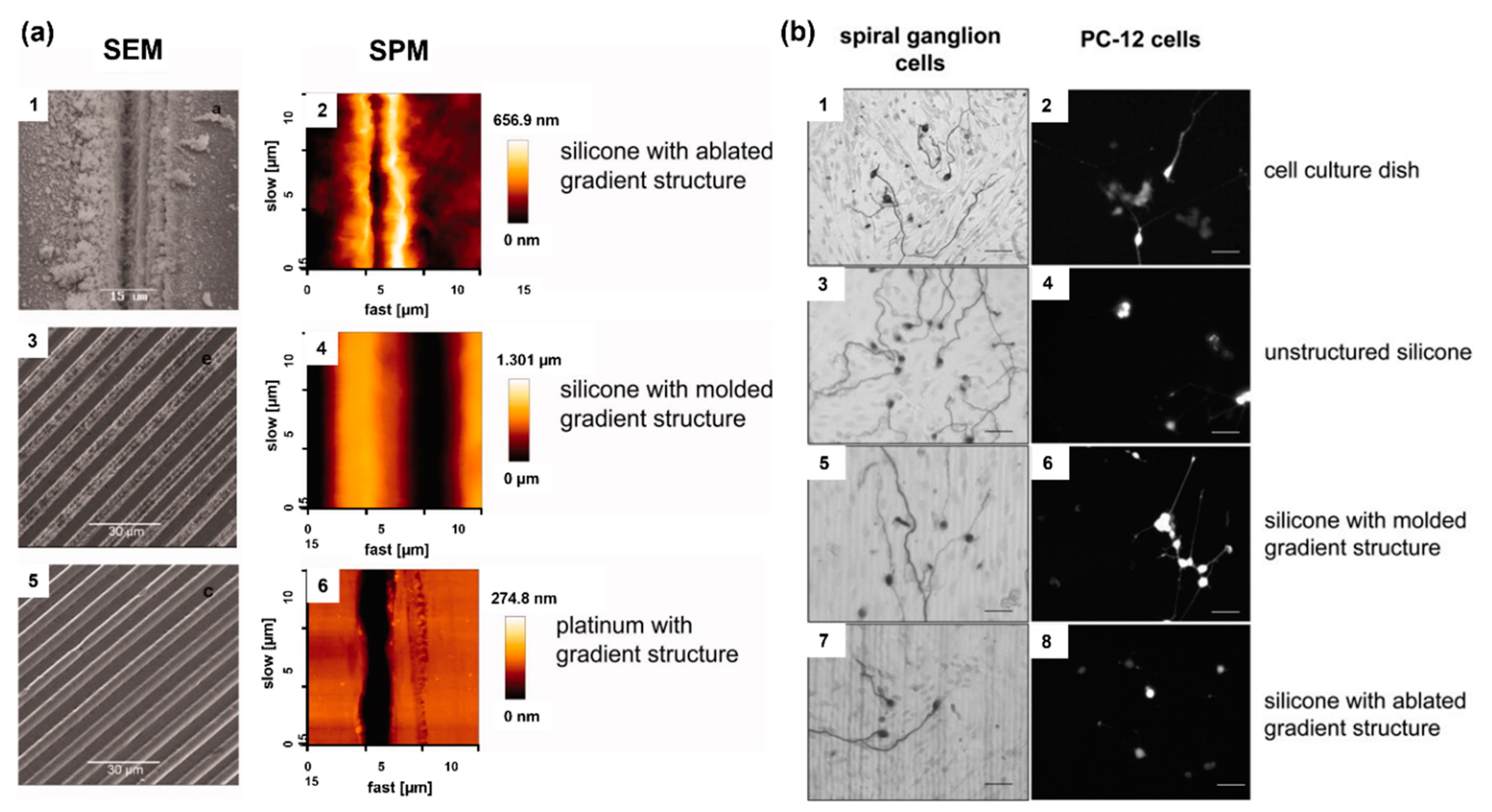
Figure 1. (a) Assessment of the various microstructures on electrode materials with scanning electrode microscopy (SEM) and scanning probe microscopy (SPM); ablated silicone elastomer (1,2), molded silicone elastomer (3,4), and platinum sputtered glass (5,6). (b) Microstructure-guided neurite outgrowth of spiral ganglion cells (left) and PC−12 cells (right) on the cell culture dish as the control (1,2) as well as on unstructured silicone (3,4), silicone molded gradient microstructure (5,6), silicone with ablated gradient microstructure (7,8). Bars: 50 μm. Reprinted with permission from [50][19]. Copyright 2012, Wiley.
2. Electrode Shape
Electrodes used in CI devices represent an approach to the realization of neural stimulation, and the geometric design of the electrodes is vitally important for nerve stimulation. However, there are limited studies on this subject. The common electrode geometry for many years has been rectangular or square in shape. Rectangular electrodes are preferred in almost all models by Advanced Bionics and MED-EL manufacturers. In the first years of CI production, ring-shaped electrode designs were developed. The biggest nuance about the electrode geometry is that electrode surface should be large enough to excite without affecting the electromagnetic fields of the nearby electrodes, hence preventing unwanted stimulation. In recent years, innovative studies on this subject have been published [57,58][26][27]. In the original electrode design, an octagonal star with pointed corners was used in order to achieve a higher electric field and sealing resistance [59][28]. Figure 2 shows the electric field generated by a star electrode and a commonly used circular electrode. The high electric field created by the eight-pointed star electrode was about three times larger than the spherical design. Another study reported high-peripheral electrodes, which have the same surface area, yet the circumference of each one of them was 2–4 times larger than that of planar electrodes with a circular shape [60][29]. Unlike electrodes with regular circumference, planar electrodes with irregular (serpentine) circumference were found to be more efficient in activating axons located farther from them and reduced power consumption by ~10%. Various computational experimental models have been developed to determine the efficiency of electrodes. The aim here is to enhance the electrical energy transmitted to the auditory nerves, thereby decreasing wasted energy, and increasing the efficiency and effectiveness of the CI system. The current distribution of the human cochlea was determined during CI electrical stimulation using finite element (FE) analysis [61][30]. The efficiency of the electrodes was assessed by applying genetic algorithms along with computational models and FE analysis to optimize the shape and dimensions of the CI electrode array. There are still not enough studies on the effect of electrode geometry on neural stimulation devices. Future research on more comprehensive studies of the electrode surface and electric fields should improve the CI design accordingly.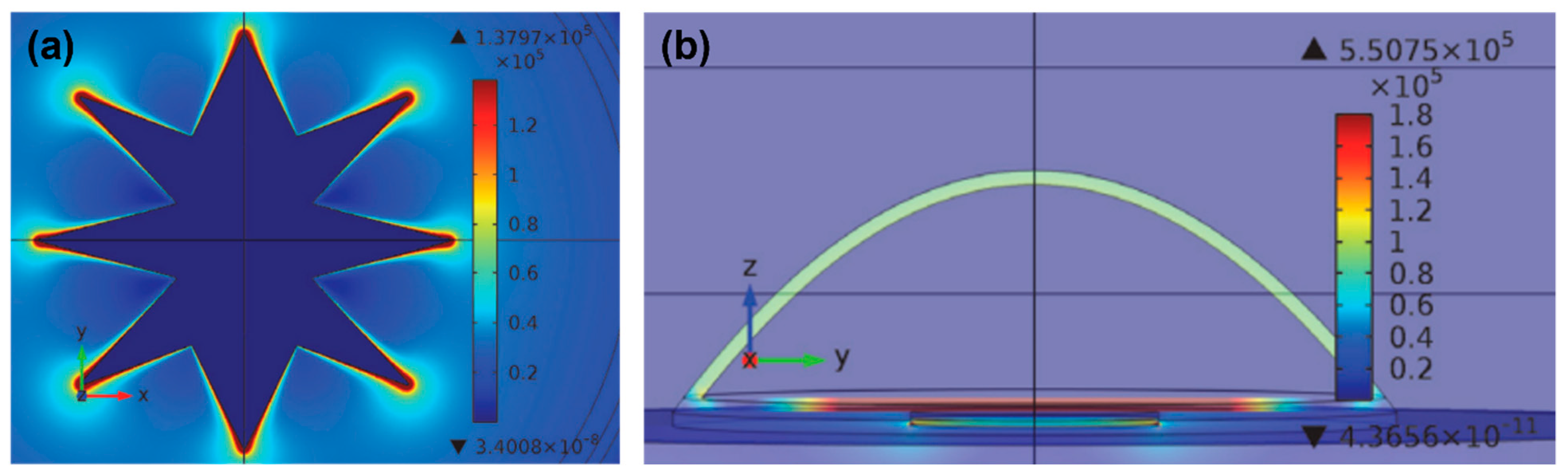
Figure 2. (a) Current density distribution on a star electrode upon −60 mV/ms of falling voltage ramp stimuli at t = 10 ms. (b) Electric field at different areas of the cell at the termination of the stimulus voltage ramp on the circular electrode. Reprinted from [59][28]. Copyright 2013 according to Attribution-NonCommercial-NoDerivatives 4.0 International (CC BY-NC-ND 4.0), which allows to copy and redistribute the material in any medium or format.
3. Effect of Electrode Spacing on Stimulation of Spiral Ganglion Cells
When sound hits the microphone, the processor receives it, amplifies it, and separates it into different frequencies with band-pass filters [6,62][31][32]. This band-pass filtered information is sent to the inner part of the CI, where the receiver decodes the band-filtered RF signals and sends current to the electrode for the stimulation of nerves [63][33]. The current generated from filtered information flows between the active and return electrodes of the CI, and the configuration of these electrodes defines channels of the choclear implant [64][34]. Each channel has defined band-pass filter [65][35]. The transmission efficiency of electrical stimulation depends on the spacing of electrodes, stimulation modes, surface of electrodes, and distance between the electrodes and nerves [66][36]. However, channel interaction due to broad spread of excitation is an inherent problem of multielectrode stimulation [18][37]. CI users suffer from insufficient spectral resolution due to channel interaction. Theoretically, an electrode stimulates the area directly facing it, but the electrical field generated by one stimulating electrode can cause the stimulation of neighboring spiral ganglion neurons [67,68][38][39]. Figure 3 shows this phenomenon, which is known as the spread of neural excitation (SOE). Unwanted overlaps of excitation may change the efficiency of subsequent stimuli, or, if sufficient, it can trigger the firing of neighboring neurons, which leads to poor vowel and consonant recognition and poor auditory rehabilitation [67][38]. Even though current CIs have 12–22 electrodes and channels, due to channel interactions, the number of independent channels is smaller than the actual number of activated electrodes [66][36]. Although interactions may occur between non-adjacent electrodes, they are greatest and strongest between adjacent electrodes [66,69][36][40]. For better hearing, larger interelectrode spacing can be used to reduce channel interactions between adjacent electrodes [19][41]. Studies have shown that improved spectral resolution and better speech understanding are achievable with lesser channel interactions [70,71,72][42][43][44].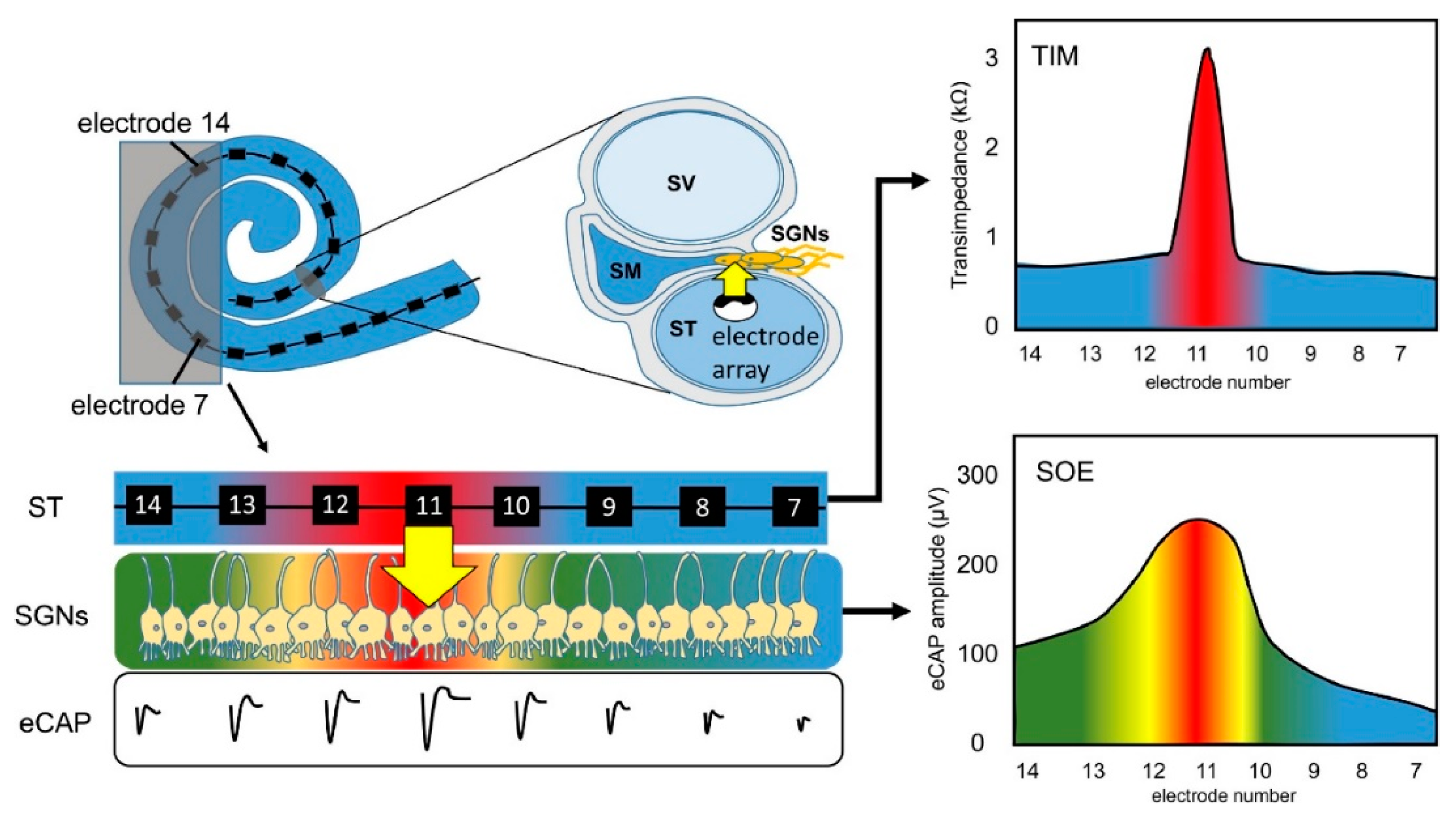
Figure 3. Principle of spread of neural excitation (SOE). Stimulation of electrode 11 spreads over neighboring electrodes and causes overlapping of excitation on spiral ganglion neurons (Scala tympani, ST; electrically evoked compound action potential, eCAP; spiral ganglion neurons, SGNs; transimpedance matrix, TIM). Reprinted with permission from [67][38]. Copyright 2021, Elsevier.
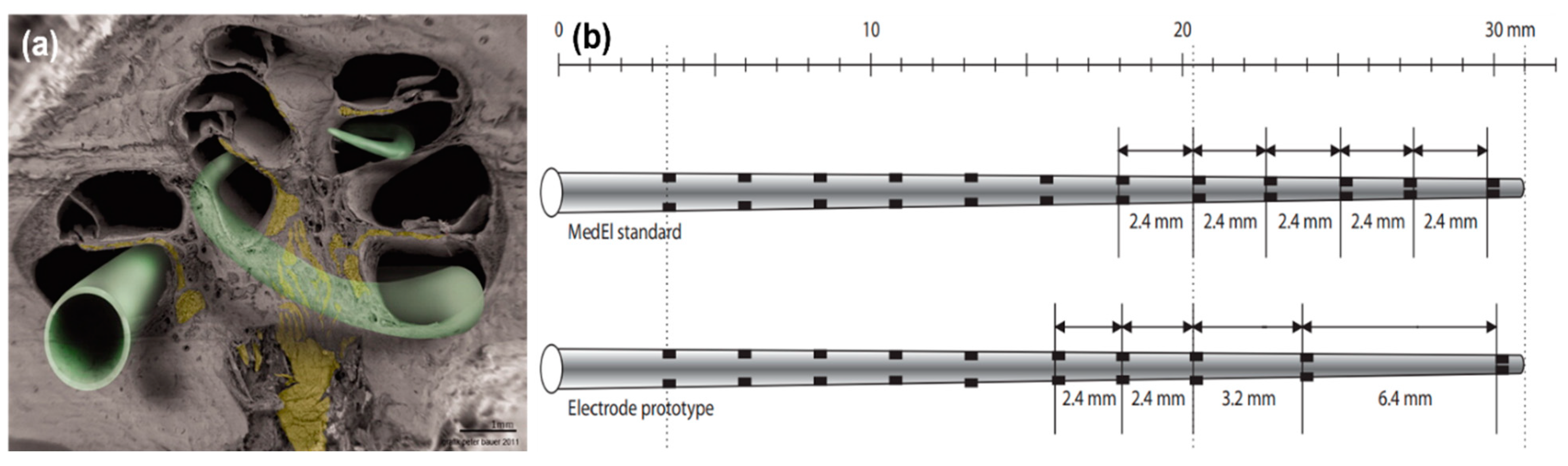
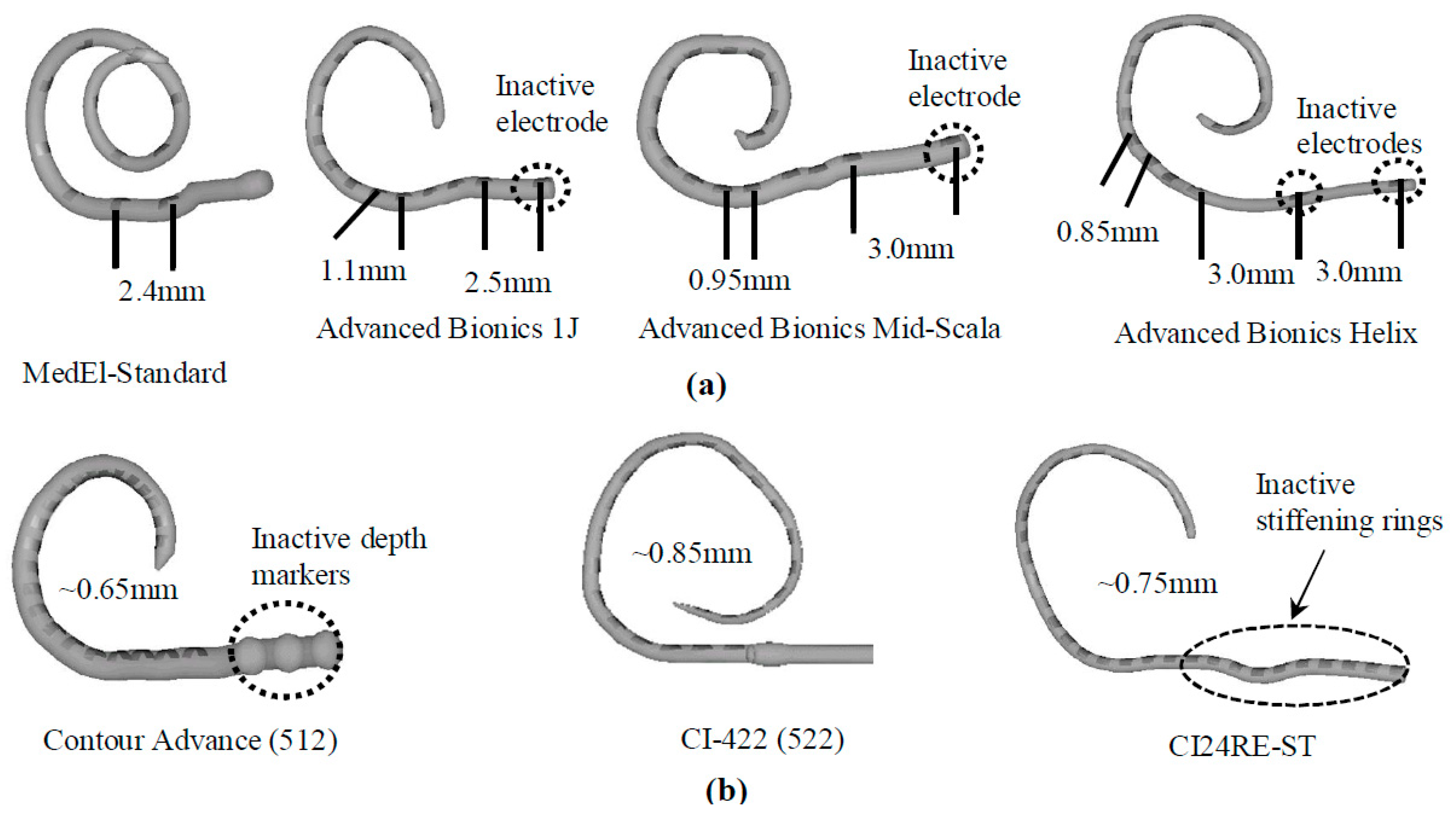
Figure 4. (a) Scanning electron microscopy (SEM) image of a hemisectioned human cochlea. Neuronal components are shown in yellow. The electrode array in green indicates potential electrode positions. Some electrode designs target the electrode array to a site close to the modiolus (perimodiolar-lower basal turn at the left lower corner of the figure), while non–preshaped electrodes are placed closer to the spiral ligament and osseous spiral lamina (other electrode positions). Reprinted with permission from [73][45]. Copyright 2012, Wiley. (b) A standard MedEl electrode array (with a length of 26.4 mm) that contains 12 electrodes. The interelectrode spacing is 2.4 mm. A prototype electrode array (with a length of 26.4 mm) that contains 10 electrodes. The interelectrode spacing is 2.4 mm to 3.2 mm in the basal and middle part and 6.4 mm in the middle and apical part of the electrode array. Reprinted with permission from [69][40], Copyright 2007, Karger.
4. Electrode Arrays
There are three types of electrode arrays, perimodiolar, lateral wall, and mid-scala. Perimodiolar electrode arrays, also called modiolus-hugging or counter type arrays, are placed close to the modiolus wall [77][49]. In this configuration, the electrode array is placed as near as possible to the modiolus, which contains spiral ganglion cells, resulting in the generation of lower electrical thresholds for stimulation, higher dynamic ranges, and less channel interaction as compared to normal implant electrodes, which are usually located peripherally within the scala tympani [36][5]. Lateral wall electrode arrays are placed along the lateral wall of the scala tympani. All lateral wall electrode arrays face the lateral wall at an angle of approximately 180°, which may lead to trauma of the scala tympani [78][50]. The perimodiolar type offers advantages over the lateral wall type in terms of lower stimulation levels, an expanded dynamic range, and better channel separation. Because perimodiolar configuration provides a placement of electrodes closer to spiral ganglions than the lateral wall, it leads to better neural stimulation, which may result in better speech perception [79][51]. Both lateral wall and perimodiolar electrode arrays can cause intra-cochlear trauma, but perimodiolar electrode arrays are likely to deviate to the scala vestibuli from the scala tympani more often than the lateral wall electrode arrays, leading to damage of the osseous spiral lamina/spiral ligament, which can induce new bone formation and ultimately impact the hearing quality [77][49]. Mid-scala electrode arrays are implanted in the middle of the scala tympani, where this design minimizes trauma to the modiolus wall or lateral wall, albeit with a lower quality of stimulation [80][52].5. Stiffness and Flexibility of Electrode Arrays
During the insertion of CI electrode arrays, different ranges of trauma may occur at the delicate anatomical regions of the cochlea such as the basilar membrane, osseous spiral lamina, scala tympani, and scala vestibuli. Intracochlear trauma may cause severe damage to the dendrites, spiral ganglion cells, and the specific distribution of these cells, and it can also result in the efficiency of the stimulation of sites located along the implant electrodes and a loss of high-fidelity sound [9,81][53][54]. It was found that 10–30% of patients lose their residual hearing after CI insertion [82][55]. Properties such as size, dimensions, and stiffness are important factors for the insertion and final positioning of electrode arrays within the scala tympani. Specifically, stiffness of electrode arrays is significantly related to the trauma to cochlear structures [9,81,83,84,85,86][53][54][56][57][58][59]. For example, if the electrode array tip is very stiff, it could penetrate the spiral ligament during insertion, and the surgeon may not feel the pressure [77][49]. The stiffness of electrode arrays is, therefore, an important factor for the effective function of CI devices. There are many factors affecting the stiffness of the electrode array, such as the size and thickness of the electrode contact pad, wire thickness and electrode material (i.e., Pt, and Pt–Ir alloy), insulating material around wires (i.e., Teflon, Parylene, and silicon), and the number of individual stimulating channels [77][49]. Wire bundling also determines the stiffness of the device. Conventional CIs contain Pt or Pt–Ir wires, which increase the stiffness of the electrode array. An electrode array with carbon nanotube (CNT) bundles instead of metal wires, where eight CNT bundles were coated with Parylene-C for insulation, was developed (Figure 6a–c) [87][60]. After coating, each CNT bundle was encapsulated with a silicone elastomer. Developed electrode array had a thickness of 135 µm at the apex and 395 µm at the base. These dimensions are smaller than those of conventional intracochlear electrode arrays. Thin and flexible CNT bundle-based electrode arrays require a sixfold lower force for insertion and extraction than metal wire-based intracochlear electrode arrays, reducing the risk of trauma [87][60]. While some CI manufacturers prefer straight wires, MED-EL uses wavy wires which spread forces and prevent electrodes from acting like needles that can cause damage during the insertion (Figure 6d) [77][49].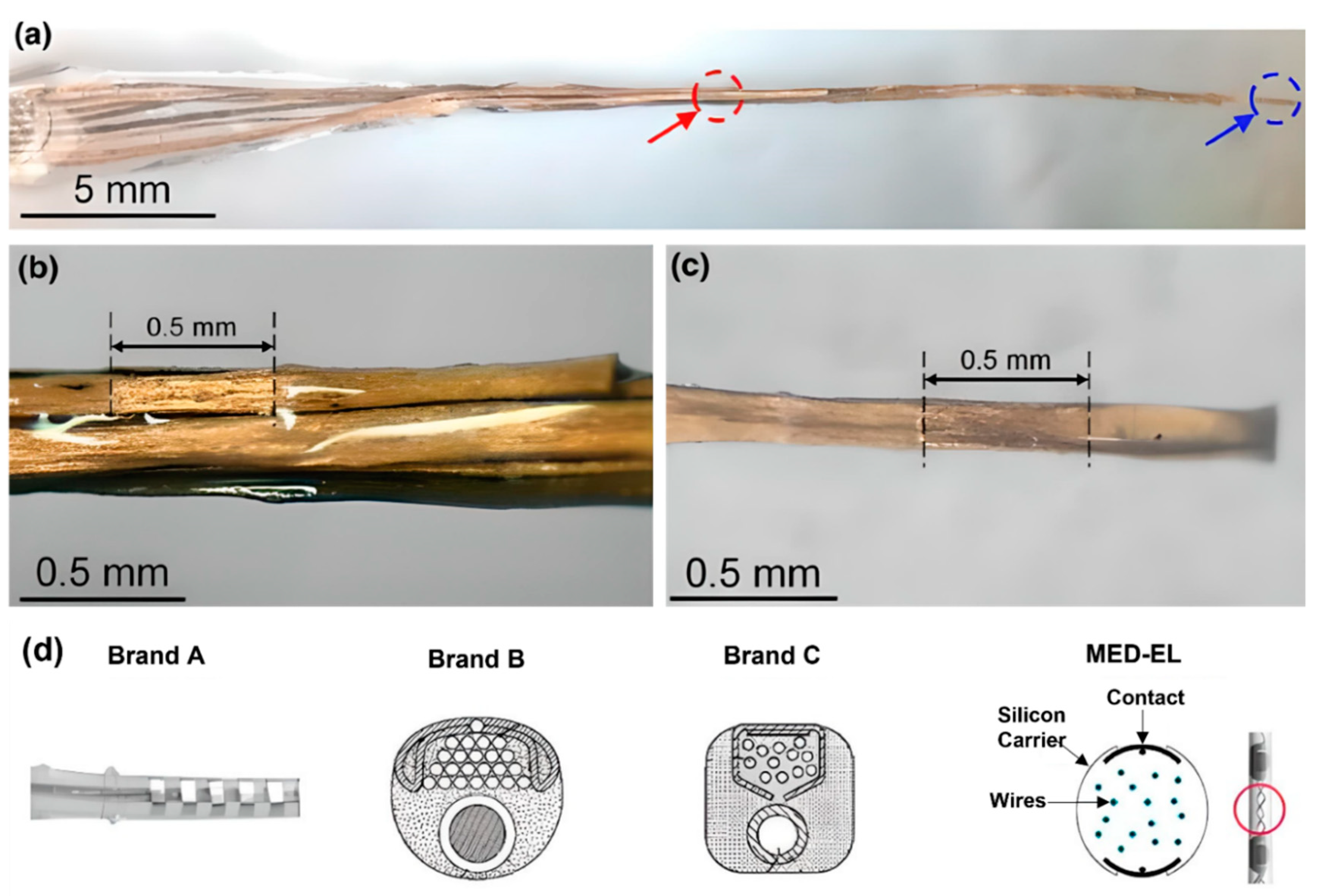
Figure 6. (a–c) Carbon nanotube (CNT) bundle-based intracochlear electrode array. (a) Red circle indicates stimulation site at the base, and blue circle indicates stimulation site at the apex of the CI. A closer photograph of the stimulation site (b) at the base, (c) at the apex. Reprinted with permission from [87][60]. Copyright 2019, Springer Nature. (d) Straight and wavy wire management/distribution of electrode arrays by brand A, B, C, and MED-EL. Reprinted with permission from [77][49]. Copyright 2017, Elsevier.
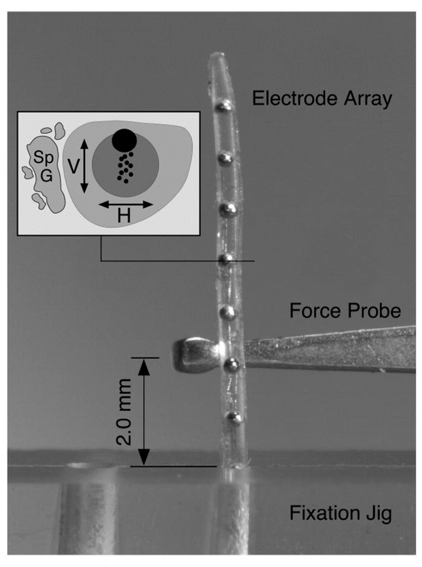
Figure 7. Deflection force required to bend each electrode array 30° at a distance of 2 mm from the fulcrum of a fixation jig that was measured with a mechanical force gauge at 1 mm intervals across the length of each electrode. The stiffness of the electrode array was deducted from the experiment. Reprinted with permission from [9][53]. Copyright 2008, United States Department of Veterans Affairs.
References
- Cogan, S.F. Neural stimulation and recording electrodes. Annu. Rev. Biomed. Eng. 2008, 10, 275–309.
- Shepherd, R.; Hatsushika, S.; Clark, G.M. Electrical stimulation of the auditory nerve: The effect of electrode position on neural excitation. Hear. Res. 1993, 66, 108–120.
- Cohen, L.T.; Saunders, E.; Knight, M.R.; Cowan, R.S. Psychophysical measures in patients fitted with Contour™ and straight Nucleus electrode arrays. Hear. Res. 2006, 212, 160–175.
- Marrinan, M.S.; Roland, J.T., Jr.; Reitzen, S.D.; Waltzman, S.B.; Cohen, L.T.; Cohen, N.L. Degree of modiolar coiling, electrical thresholds, and speech perception after cochlear implantation. Otol. Neurotol. 2004, 25, 290–294.
- Gstoettner, W.K.; Adunka, O.; Franz, P.; Hamzavi, J.; Plenk, H., Jr.; Susani, M.; Baumgartner, W.; Kiefer, J. Perimodiolar electrodes in cochlear implant surgery. Acta Oto-Laryngol. 2001, 121, 216–219.
- Lenarz, T.; Stöver, T.; Buechner, A.; Paasche, G.; Briggs, R.; Risi, F.; Pesch, J.; Battmer, R.-D. Temporal bone results and hearing preservation with a new straight electrode. Audiol. Neurotol. 2006, 11, 34–41.
- Stieghorst, J.; Tegtmeier, K.; Aliuos, P.; Zernetsch, H.; Glasmacher, B.; Doll, T. Self-bending hydrogel actuation for electrode shafts in cochlear implants. Phys. Status Solidi (A) 2014, 211, 1455–1461.
- Jang, J.; Kim, J.Y.; Kim, Y.C.; Kim, S.; Chou, N.; Lee, S.; Choung, Y.H.; Kim, S.; Brugger, J.; Choi, H. A 3D microscaffold cochlear electrode array for steroid elution. Adv. Healthc. Mater. 2019, 8, 1900379.
- Jia, H.; François, F.; Bourien, J.; Eybalin, M.; Lloyd, R.; Van De Water, T.; Puel, J.-L.; Venail, F. Prevention of trauma-induced cochlear fibrosis using intracochlear application of anti-inflammatory and antiproliferative drugs. Neuroscience 2016, 316, 261–278.
- Fayad, J.N.; Makarem, A.O.; Linthicum, F.H., Jr. Histopathologic assessment of fibrosis and new bone formation in implanted human temporal bones using 3D reconstruction. Otolaryngol.—Head Neck Surg. 2009, 141, 247–252.
- Bas, E.; Dinh, C.T.; Garnham, C.; Polak, M.; Van de Water, T.R. Conservation of hearing and protection of hair cells in cochlear implant patients’ with residual hearing. Anat. Rec. Adv. Integr. Anat. Evol. Biol. 2012, 295, 1909–1927.
- Jia, H.; Wang, J.; François, F.; Uziel, A.; Puel, J.-L.; Venail, F. Molecular and cellular mechanisms of loss of residual hearing after cochlear implantation. Ann. Otol. Rhinol. Laryngol. 2013, 122, 33–39.
- Ceschi, P.; Bohl, A.; Sternberg, K.; Neumeister, A.; Senz, V.; Schmitz, K.; Kietzmann, M.; Scheper, V.; Lenarz, T.; Stöver, T. Biodegradable polymeric coatings on cochlear implant surfaces and their influence on spiral ganglion cell survival. J. Biomed. Mater. Res. Part B Appl. Biomater. 2014, 102, 1255–1267.
- Bas, E.; Bohorquez, J.; Goncalves, S.; Perez, E.; Dinh, C.T.; Garnham, C.; Hessler, R.; Eshraghi, A.A.; Van De Water, T.R. Electrode array-eluted dexamethasone protects against electrode insertion trauma induced hearing and hair cell losses, damage to neural elements, increases in impedance and fibrosis: A dose response study. Hear. Res. 2016, 337, 12–24.
- Eftekhari, A.; Maleki Dizaj, S.; Sharifi, S.; Salatin, S.; Rahbar Saadat, Y.; Zununi Vahed, S.; Samiei, M.; Ardalan, M.; Rameshrad, M.; Ahmadian, E. The use of nanomaterials in tissue engineering for cartilage regeneration; current approaches and future perspectives. Int. J. Mol. Sci. 2020, 21, 536.
- Kather, M.; Koitzsch, S.; Breit, B.; Plontke, S.; Kammerer, B.; Liebau, A. Metabolic reprogramming of inner ear cell line HEI-OC1 after dexamethasone application. Metabolomics 2021, 17, 52.
- Luo, Y.; Chen, A.; Xu, M.; Chen, D.; Tang, J.; Ma, D.; Zhang, H. Preparation, characterization, and in vitro/vivo evaluation of dexamethasone/poly (ε-caprolactone)-based electrode coatings for cochlear implants. Drug Deliv. 2021, 28, 1673–1684.
- Linke, I.; Fadeeva, E.; Scheper, V.; Esser, K.H.; Koch, J.; Chichkov, B.N.; Lenarz, T.; Paasche, G. Nanostructuring of cochlear implant electrode contacts induces delayed impedance increase in vivo. Phys. Status Solidi (A) 2015, 212, 1210–1215.
- Reich, U.; Fadeeva, E.; Warnecke, A.; Paasche, G.; Müller, P.; Chichkov, B.; Stöver, T.; Lenarz, T.; Reuter, G. Directing neuronal cell growth on implant material surfaces by microstructuring. J. Biomed. Mater. Res. Part B Appl. Biomater. 2012, 100, 940–947.
- Ashammakhi, N. Reactions to biomaterials: The good, the bad, and ideas for developing new therapeutic approaches. J. Craniofac. Surg. 2005, 16, 195–196.
- Ashammakhi, N.; Waris, T.; Serlo, W.; Törmälä, P. Self-reinforced bioabsorbable devices for osteofixation of craniofacial bones. In Biomaterials in Orthopedics; Yaszemski, M.J., Trantolo, D.J., Lewandrowski, K.-U., Hasirci, V., Altobelli, D.E., Wise, D.L., Eds.; Marcel Dekker, Inc.: New York, NY, USA, 2004.
- O’Malley, J.T.; Burgess, B.J.; Galler, D.; Nadol, J.B., Jr. Foreign body response to silicone in cochlear implant electrodes in the human. Otol. Neurotol. Off. Publ. Am. Otol. Soc. Am. Neurotol. Soc. Eur. Acad. Otol. Neurotol. 2017, 38, 970.
- Dalrymple, A.N.; Huynh, M.; Nayagam, B.A.; Lee, C.D.; Weiland, G.R.; Petrossians, A.; John, J.; Fallon, J.B.; Shepherd, R.K. Electrochemical and biological characterization of thin-film platinum-iridium alloy electrode coatings: A chronic in vivo study. J. Neural Eng. 2020, 17, 036012.
- Tegtmeier, K.; Aliuos, P.; Stieghorst, J.; Schickedanz, M.; Golly, F.; Zernetsch, H.; Glasmacher, B.; Doll, T. Aligned carbon nanotube-liquid silicone rubber conductors and electrode surfaces for stimulating medical implants. Phys. Status Solidi (A) 2014, 211, 1439–1447.
- Peck, C.-T.; Schwieger, J.; Lenarz, T.; Scheper, V. Stability and Biocompatibility Tests of Alginate as Cochlear Implant Coating Material. Curr. Dir. Biomed. Eng. 2021, 7, 775–778.
- Choi, C. Shape optimization of cochlear implant electrode array using genetic algorithms. In Proceedings of the 2001 Conference Proceedings of the 23rd Annual International Conference of the IEEE Engineering in Medicine and Biology Society, Istanbul, Turkey, 25–28 October 2001; pp. 1445–1448.
- Nigam, A.; Ahmed, F.; Pawar, S. Design and simulation of geometrical shape and size variations of micro-electrode for cochlear implant. In Biotechnological Applications in Human Health; Springer: Berlin/Heidelberg, Germany, 2020; pp. 69–75.
- Ghazavi, A.; Westwick, D.T.; Luk, C.; Syed, N.; Dalton, C. Improving Neuron Stimulation Efficency by Altering Electrode Geometry. In Proceedings of the BIODEVICES-2013, Barcelona, Spain, 11–14 February 2013; pp. 51–56.
- Wei, X.F.; Grill, W.M. Analysis of high-perimeter planar electrodes for efficient neural stimulation. Front. Neuroeng. 2009, 2, 15.
- Choi, C.T.; Lai, W.-D.; Chen, Y.-B. Optimization of cochlear implant electrode array using genetic algorithms and computational neuroscience models. IEEE Trans. Magn. 2004, 40, 639–642.
- Zeng, F.-G.; Rebscher, S.; Harrison, W.; Sun, X.; Feng, H. Cochlear implants: System design, integration, and evaluation. IEEE Rev. Biomed. Eng. 2008, 1, 115–142.
- Boucherit, I.; Guerti, M. Speech analysis in cochlear implant using auditory filter bank model. In Proceedings of the 2016 8th International Conference on Modelling, Identification and Control (ICMIC), Algiers, Algeria, 15–17 November 2016; pp. 274–278.
- Macherey, O.; Carlyon, R.P. Cochlear implants. Curr. Biol. 2014, 24, R878–R884.
- Arenberg Bierer, J. Probing the electrode-neuron interface with focused cochlear implant stimulation. Trends Amplif. 2010, 14, 84–95.
- Kim, K.H.; Choi, S.J.; Kim, J.H. A sound processor for cochlear implant using a simple dual path nonlinear model of basilar membrane. Comput. Math. Methods Med. 2013, 2013, 153039.
- Joly, C.-A.; Reynard, P.; Hermann, R.; Seldran, F.; Gallego, S.; Idriss, S.; Thai-Van, H. Intra-Cochlear Current Spread Correlates with Speech Perception in Experienced Adult Cochlear Implant Users. J. Clin. Med. 2021, 10, 5819.
- Padilla, M.; Landsberger, D.M. Reduction in spread of excitation from current focusing at multiple cochlear locations in cochlear implant users. Hear. Res. 2016, 333, 98–107.
- Söderqvist, S.; Lamminmäki, S.; Aarnisalo, A.; Hirvonen, T.; Sinkkonen, S.T.; Sivonen, V. Intraoperative transimpedance and spread of excitation profile correlations with a lateral-wall cochlear implant electrode array. Hear. Res. 2021, 405, 108235.
- Cucis, P.-A.; Berger-Vachon, C.; Hermann, R.; Thai-Van, H.; Gallego, S.; Truy, E. Cochlear Implant: Effect of the Number of Channel and Frequency Selectivity on Speech Understanding in Noise Preliminary Results in Simulation with Normal-Hearing Subjects. Model. Meas. Control C 2020, 81, 17–23.
- Arnoldner, C.; Riss, D.; Baumgartner, W.-D.; Kaider, A.; Hamzavi, J.-S. Cochlear implant channel separation and its influence on speech perception–implications for a new electrode design. Audiol. Neurotol. 2007, 12, 313–324.
- Büchner, A.; Illg, A.; Majdani, O.; Lenarz, T. Investigation of the effect of cochlear implant electrode length on speech comprehension in quiet and noise compared with the results with users of electro-acoustic-stimulation, a retrospective analysis. PLoS ONE 2017, 12, e0174900.
- Berenstein, C.K.; Mens, L.H.; Mulder, J.J.; Vanpoucke, F.J. Current steering and current focusing in cochlear implants: Comparison of monopolar, tripolar, and virtual channel electrode configurations. Ear Hear. 2008, 29, 250–260.
- Smith, Z.M.; Parkinson, W.S.; Long, C.J. Multipolar current focusing increases spectral resolution in cochlear implants. In Proceedings of the 2013 35th Annual International Conference of the IEEE Engineering in Medicine and Biology Society (EMBC), Osaka, Japan, 3–7 July 2013; pp. 2796–2799.
- Srinivasan, A.G.; Padilla, M.; Shannon, R.V.; Landsberger, D.M. Improving speech perception in noise with current focusing in cochlear implant users. Hear. Res. 2013, 299, 29–36.
- Rask-Andersen, H.; Liu, W.; Erixon, E.; Kinnefors, A.; Pfaller, K.; Schrott-Fischer, A.; Glueckert, R. Human cochlea: Anatomical characteristics and their relevance for cochlear implantation. Anat. Rec. Adv. Integr. Anat. Evol. Biol. 2012, 295, 1791–1811.
- Zhao, Y.; Chakravorti, S.; Labadie, R.F.; Dawant, B.M.; Noble, J.H. Automatic graph-based method for localization of cochlear implant electrode arrays in clinical CT with sub-voxel accuracy. Med. Image Anal. 2019, 52, 1–12.
- Zhao, Y. Automatic techniques for cochlear implant CT image analysis. arXiv 2019, arXiv:1909.10922.
- Landsberger, D.M.; Mertens, G.; Punte, A.K.; Van De Heyning, P. Perceptual changes in place of stimulation with long cochlear implant electrode arrays. J. Acoust. Soc. Am. 2014, 135, EL75–EL81.
- Dhanasingh, A.; Jolly, C. An overview of cochlear implant electrode array designs. Hear. Res. 2017, 356, 93–103.
- Risi, F. Considerations and rationale for cochlear implant electrode design-past, present and future. J. Int. Adv. Otol. 2018, 14, 382.
- Lee, J.Y.; Hong, S.H.; Moon, I.J.; Kim, E.Y.; Baek, E.; Seol, H.Y.; Kang, S. Effect of cochlear implant electrode array design on electrophysiological and psychophysical measures: Lateral wall versus perimodiolar types. J. Audiol. Otol. 2019, 23, 145.
- Boyle, P. The rationale for a mid-scala electrode array. Eur. Ann. Otorhinolaryngol. Head Neck Dis. 2016, 133, S61–S62.
- Rebscher, S.J.; Hetherington, A.; Bonham, B.; Wardrop, P.; Whinney, D.; Leake, P.A. Considerations for the design of future cochlear implant electrode arrays: Electrode array stiffness, size and depth of insertion. J. Rehabil. Res. Dev. 2008, 45, 731.
- Kha, H.N.; Chen, B.K.; Clark, G.M.; Jones, R. Stiffness properties for Nucleus standard straight and contour electrode arrays. Med. Eng. Phys. 2004, 26, 677–685.
- Drouillard, M.; Torres, R.; Mamelle, E.; De Seta, D.; Sterkers, O.; Ferrary, E.; Nguyen, Y. Influence of electrode array stiffness and diameter on hearing in cochlear implanted guinea pig. PLoS ONE 2017, 12, e0183674.
- Patrick, J.; MacFarlane, J. Characterization of mechanical properties of single electrodes and multielectrodes. Ann. Otol. Rhinol. Laryngol. 1987, 96, 46–48.
- Kha, H.; Chen, B. Finite element analysis of damage by cochlear implant electrode array’s proximal section to the basilar membrane. Otol. Neurotol. 2012, 33, 1176–1180.
- Chen, B.K.; Clark, G.M.; Jones, R. Evaluation of trajectories and contact pressures for the straight nucleus cochlear implant electrode array—A two-dimensional application of finite element analysis. Med. Eng. Phys. 2003, 25, 141–147.
- Lim, Y.S.; Park, S.-I.; Kim, Y.H.; Oh, S.H.; Kim, S.J. Three-dimensional analysis of electrode behavior in a human cochlear model. Med. Eng. Phys. 2005, 27, 695–703.
- Choi, G.J.; Gwon, T.M.; Kim, D.H.; Park, J.; Kim, S.M.; Oh, S.H.; Lim, Y.; Jun, S.B.; Kim, S.J. CNT bundle-based thin intracochlear electrode array. Biomed. Microdevices 2019, 21, 27.
- Johnson, A.C.; Wise, K.D. An active thin-film cochlear electrode array with monolithic backing and curl. J. Microelectromech. Syst. 2013, 23, 428–437.
- Bhatti, P.T.; Wise, K.D. A 32-site 4-channel high-density electrode array for a cochlear prosthesis. IEEE J. Solid-State Circuits 2006, 41, 2965–2973.
- Wang, J.; Wise, K.D. A thin-film cochlear electrode array with integrated position sensing. J. Microelectromech. Syst. 2009, 18, 385–395.
- Xu, Y.; Luo, C.; Zeng, F.-G.; Middlebrooks, J.C.; Lin, H.W.; You, Z. Study of the carrier-aided thin film electrode array design for cochlear insertion. Micromachines 2018, 9, 206.
- Boyer, E.; Karkas, A.; Attye, A.; Lefournier, V.; Escude, B.; Schmerber, S. Scalar localization by cone-beam computed tomography of cochlear implant carriers: A comparative study between straight and periomodiolar precurved electrode arrays. Otol. Neurotol. 2015, 36, 422–429.
More