Laser Doppler vibrometry (LDV) is a non-contact vibration measurement technique based on the Doppler effect of the reflected laser beam. Thanks to its feature of high resolution and flexibility, LDV has been used in many different fields today. The miniaturization of the LDV systems is one important development direction for the current LDV systems that can enable many new applications.
- laser Doppler vibrometry
- miniaturization
- photonic integrated circuit
1. PIC-Based LDV
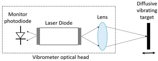
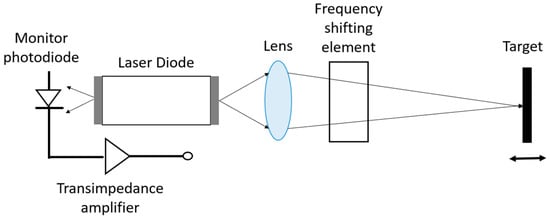
2. Self-Mixing LDV
 where the following
is the coupling strength coefficient of external reflection, R is the reflectance of light at the laser facet, R2 is the reflectance of the target, ε is the loss of reflected light caused by, e.g., mode mismatch, α is the linewidth enhancement factor of the laser, τext is the round-trip time of flight in the external cavity, and τlaser
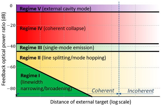
is the round-trip time of flight in the laser cavity. To be more specific, there are five different performance regimes in self-mixing interferometry
(see
) that correspond to different monitoring shapes. For self-mixing LDVs, the researchers only discuss the phenomenon in regimes I–III. They are the weak optical feedback regime I (
≤ 1), moderate optical feedback regime II (
> 1), and strong optical feedback regime III (
>> 1). When the reflection is even stronger, the system will be working the regime IV or V, where the self-mixing technique will not be applicable. To be in the self-mixing regime, the feedback power should be reduced by more than 35 dB.
3. Micromachined Free-Space Interferometer of LDV
References
- Jian Wang; Yun Long; On-chip silicon photonic signaling and processing: a review. Science Bulletin 2018, 63, 1267-1310, 10.1016/j.scib.2018.05.038.
- Po Dong; Young-Kai Chen; Guang-Hua Duan; David T. Neilson; Silicon photonic devices and integrated circuits. Nanophotonics 2014, 3, 215-228, 10.1515/nanoph-2013-0023.
- Jianwei Wang; Alberto Santamato; Pisu Jiang; Damien Bonneau; Erman Engin; Joshua W. Silverstone; Matthias Lermer; Johannes Beetz; Martin Kamp; Sven Höfling; et al.Michael G. TannerChandra M. NatarajanRobert H. HadfieldSander N. DorenbosVal ZwillerJeremy L. O’BrienMark G. Thompson Gallium arsenide (GaAs) quantum photonic waveguide circuits. Optics Communications 2014, 327, 49-55, 10.1016/j.optcom.2014.02.040.
- Christof P. Dietrich; Andrea Fiore; Mark G. Thompson; Martin Kamp; Sven Höfling; GaAs integrated quantum photonics: Towards compact and multi-functional quantum photonic integrated circuits (Laser Photonics Rev. 10(6)/2016). Laser & Photonics Reviews 2016, 10, 857-857, 10.1002/lpor.201670065.
- Meint Smit; Xaveer Leijtens; Huub Ambrosius; Erwin Bente; Jos Van Der Tol; Barry Smalbrugge; Tjibbe De Vries; Erik-Jan Geluk; Jeroen Bolk; Rene Van Veldhoven; et al.Luc AugustinPeter ThijsDomenico D’AgostinoHadi RabbaniKatarzyna LawniczukStanisław StopińskiSaeed TahviliAntonio CorradiEmil KleijnDzmitry DzibrouManuela FelicettiElton BitinckaValentina MoskalenkoJing ZhaoRui SantosGiovanni GilardiWeiming YaoKevin WilliamsPatty StabilePiet KuindersmaJosselin PelloSrivathsa BhatYuqing JiaoDominik HeissGunther RoelkensMike WalePaul FirthFrancisco SoaresNorbert GroteMartin SchellHelene DebregeasMohand AchoucheJean-Louis GentnerArjen BakkerTwan KorthorstDominic GallagherAndrew DabbsAndrea Ivano MelloniFrancesco MorichettiDaniele MelatiAdrian WonforRichard PentyRonald BroekeBob MuskDave Robbins An introduction to InP-based generic integration technology. Semiconductor Science and Technology 2014, 29, 083001, 10.1088/0268-1242/29/8/083001.
- Meint Smit; Kevin Williams; Jos Van Der Tol; Past, present, and future of InP-based photonic integration. APL Photonics 2019, 4, 050901, 10.1063/1.5087862.
- A. Rubiyanto; H. Herrmann; R. Ricken; F. Tian; W. Sohler; Integrated Optical Heterodyne Interferometer in Lithium Niobate. Journal of Nonlinear Optical Physics & Materials 2001, 10, 163-168, 10.1142/s0218863501000516.
- Hiroshi Takahashi; High performance planar lightwave circuit devices for large capacity transmission. Optics Express 2011, 19, B173-B180, 10.1364/oe.19.00b173.
- Daniel J. Blumenthal; Rene Heideman; Douwe Geuzebroek; Arne Leinse; Chris Roeloffzen; Silicon Nitride in Silicon Photonics. Proceedings of the IEEE 2018, 106, 2209-2231, 10.1109/jproc.2018.2861576.
- Abdul Rahim; Eva Ryckeboer; Ananth Z. Subramanian; Stephane Clemmen; Bart Kuyken; Ashim Dhakal; Ali Raza; Artur Hermans; Muhammad Muneeb; Soren Dhoore; et al.Yanlu LiUtsav DavePeter BienstmanNicolas Le ThomasGunther RoelkensDries Van ThourhoutPhilippe HelinSimone SeveriXavier RottenbergRoel Baets Expanding the Silicon Photonics Portfolio With Silicon Nitride Photonic Integrated Circuits. Journal of Lightwave Technology 2016, 35, 639-649, 10.1109/jlt.2016.2617624.
- Roger Dangel; Antonio La Porta; Daniel Jubin; Folkert Horst; Norbert Meier; Marc Seifried; Bert J. Offrein; Polymer Waveguides Enabling Scalable Low-Loss Adiabatic Optical Coupling for Silicon Photonics. IEEE Journal of Selected Topics in Quantum Electronics 2018, 24, 1-11, 10.1109/jstqe.2018.2812603.
- Shankar Kumar Selvaraja, Purnima Sethi. Review on Optical Waveguides; Kok Yeow You, Eds.; IntechOpen : Vienna, Austria, 2018; pp. 384 .
- Corning, S.M.F. 28e Optical Fiber Product Information; Corning: New York, NY, USA, 2005.
- Slevaraja, S. Wafer-Scale Fabrication Technology for Silicon Photonic Integrated Circuits. Ph.D. Thesis, Ghent University, Ghent, Belgium, 2011.
- W. Bogaerts; S. K. Selvaraja; Compact Single-Mode Silicon Hybrid Rib/Strip Waveguide With Adiabatic Bends. IEEE Photonics Journal 2011, 3, 422-432, 10.1109/jphot.2011.2142931.
- Eric Dulkeith; Yurii A Vlasov; Xiaogang Chen; Nicolae C Panoiu; Richard M Osgood; Self-phase-modulation in submicron silicon-on-insulator photonic wires.. Optics Express 2006, 14, 5524–5534.
- Yanlu Li; Roel Baets; Homodyne laser Doppler vibrometer on silicon-on-insulator with integrated 90 degree optical hybrids. Optics Express 2013, 21, 13342-13350, 10.1364/oe.21.013342.
- José Manuel Luque‐González; Robert Halir; Juan Gonzalo Wangüemert‐Pérez; José De‐Oliva‐Rubio; Jens H. Schmid; Pavel Cheben; Íñigo Molina‐Fernández; Alejandro Ortega‐Moñux; An Ultracompact GRIN‐Lens‐Based Spot Size Converter using Subwavelength Grating Metamaterials. Laser & Photonics Reviews 2019, 13, 1900172, 10.1002/lpor.201900172.
- Dirk Taillaert; Frederik Van Laere; Melanie Ayre; Wim Bogaerts; Dries Van Thourhout; Peter Bienstman; Roel Baets; Grating Couplers for Coupling between Optical Fibers and Nanophotonic Waveguides. Japanese Journal of Applied Physics 2006, 45, 6071-6077, 10.1143/jjap.45.6071.
- Steven J. Koester; Jeremy D. Schaub; Gabriel Dehlinger; Jack O. Chu; Germanium-on-SOI Infrared Detectors for Integrated Photonic Applications. IEEE Journal of Selected Topics in Quantum Electronics 2006, 12, 1489-1502, 10.1109/jstqe.2006.883160.
- Di Liang; John E. Bowers; Recent Progress in Heterogeneous III-V-on-Silicon Photonic Integration. Light: Advanced Manufacturing 2021, 2, 59-25, 10.37188/lam.2021.005.
- Matthieu Duperron; Lee Carroll; Marc Rensing; Sean Collins; Yan Zhao; Yanlu Li; Roel Baets; Peter O'Brien; Hybrid integration of laser source on silicon photonic integrated circuit for low-cost interferometry medical device. Imaging, Manipulation, and Analysis of Biomolecules, Cells, and Tissues XII 2017, 10109, 1010915-1010915-17, 10.1117/12.2250921.
- Thomas Taimre; Milan Nikolić; Karl Bertling; Yah Leng Lim; Thierry Bosch; Aleksandar D. Rakić; Laser feedback interferometry: a tutorial on the self-mixing effect for coherent sensing. Advances in Optics and Photonics 2015, 7, 570-631, 10.1364/aop.7.000570.
- Jiyang Li; Haisha Niu; Yan Xiong Niu; Laser feedback interferometry and applications: a review. Optical Engineering 2017, 56, 050901-050901, 10.1117/1.oe.56.5.050901.
- Yu Zhao; Julien Perchoux; Lucie Campagnolo; Thierry Camps; Reza Atashkhooei; Véronique Bardinal; Optical feedback interferometry for microscale-flow sensing study: numerical simulation and experimental validation. Optics Express 2016, 24, 23849, 10.1364/oe.24.023849.
- King, P.; Steward, G. Metrology with an optical maser. New Sci. 1963, 17, 180.
- M J Rudd; A laser Doppler velocimeter employing the laser as a mixer-oscillator. Journal of Physics E: Scientific Instruments 1968, 1, 723-726, 10.1088/0022-3735/1/7/305.
- Edson T. Shimizu; Directional discrimination in the self-mixing type laser Doppler velocimeter. Applied Optics 1987, 26, 4541-4544, 10.1364/ao.26.004541.
- M. H. Koelink; M. Slot; F. F. M. De Mul; J. Greve; R. Graaff; A. C. M. Dassel; J. G. Aarnoudse; Laser Doppler velocimeter based on the self-mixing effect in a fiber-coupled semiconductor laser: theory. Applied Optics 1992, 31, 3401-3408, 10.1364/ao.31.003401.
- R. Tkach; A. Chraplyvy; Regimes of feedback effects in 1.5-µm distributed feedback lasers. Journal of Lightwave Technology 1986, 4, 1655-1661, 10.1109/jlt.1986.1074666.
- S. Donati; Developing self-mixing interferometry for instrumentation and measurements. Laser & Photonics Reviews 2011, 6, 393-417, 10.1002/lpor.201100002.
- Peter J. De Groot; Gregg M. Gallatin; Steven H. Macomber; Ranging and velocimetry signal generation in a backscatter-modulated laser diode. Applied Optics 1988, 27, 4475-4480, 10.1364/ao.27.004475.
- W. M. Wang; W. J. O. Boyle; K. T. V. Grattan; A. W. Palmer; Self-mixing interference in a diode laser: experimental observations and theoretical analysis. Applied Optics 1993, 32, 1551-1558, 10.1364/ao.32.001551.
- R. Lang; K. Kobayashi; External optical feedback effects on semiconductor injection laser properties. IEEE Journal of Quantum Electronics 1980, 16, 347-355, 10.1109/jqe.1980.1070479.
- Yufeng Tao; Ming Wang; Wei Xia; Carrier-separating demodulation of phase shifting self-mixing interferometry. Optics & Laser Technology 2017, 89, 75-85, 10.1016/j.optlastec.2016.08.013.
- S. Donati; G. Giuliani; S. Merlo; Laser diode feedback interferometer for measurement of displacements without ambiguity. IEEE Journal of Quantum Electronics 1995, 31, 113-119, 10.1109/3.341714.
- G. Plantier; C. Bes; T. Bosch; Behavioral model of a self-mixing laser diode sensor. IEEE Journal of Quantum Electronics 2005, 41, 1157-1167, 10.1109/jqe.2005.853364.
- T. Giallorenzi; J. Bucaro; A. Dandridge; G. Sigel; J. Cole; S. Rashleigh; R. Priest; Optical fiber sensor technology. IEEE Journal of Quantum Electronics 1982, 18, 626-665, 10.1109/jqe.1982.1071566.
- S. Donati; Laser interferometry by induced modulation of cavity field. Journal of Applied Physics 1978, 49, 495-497, 10.1063/1.324672.
- Guido Giuliani; Simone Bozzi-Pietra; Silvano Donati; Self-mixing laser diode vibrometer. Measurement Science and Technology 2002, 14, 24-32, 10.1088/0957-0233/14/1/304.
- Jiyang Li; Haisha Niu; Laser feedback interferometry and applications: a review. Optical Engineering 2017, 56, 050901-050901, 10.1117/1.oe.56.5.050901.
- Zang, D.; Millerd, J. Heterodyned Self-Mixing Laser Diode Vibrometer. U.S. Patent 5,838,439, 17 November 1998.
- Y. Fu; M. Guo; P. B. Phua; Spatially encoded multibeam laser Doppler vibrometry using a single photodetector. Optics Letters 2010, 35, 1356-1358, 10.1364/ol.35.001356.
- Yasser M. Sabry; Diaa Khalil; Tarik Bourouina; Monolithic silicon-micromachined free-space optical interferometers onchip. Laser & Photonics Review 2014, 9, 1-24, 10.1002/lpor.201400069.
- Kyoungsik Yu; Daesung Lee; Uma Krishnamoorthy; Namkyoo Park; Olav Solgaard; Micromachined Fourier transform spectrometer on silicon optical bench platform. Sensors and Actuators A: Physical 2006, 130-131, 523-530, 10.1016/j.sna.2005.12.022.
- B. Saadany; H. Omran; M. Medhat; F. Marty; D. Khalil; T. Bourouina; MEMS tunable Michelson interferometer with robust beam splitting architecture. 2009 IEEE/LEOS International Conference on Optical MEMS and Nanophotonics 2009, -, 49-50, 10.1109/omems.2009.5338601.
- Hichem Nouira; Jean-Pierre Wallerand; Maurine Malak; Anne-Françoise Obaton; José Salgado; Tarik Bourouina; Miniature silicon Michelson interferometer characterization for dimensional metrology. Sensors and Actuators A: Physical 2015, 223, 141-150, 10.1016/j.sna.2014.12.031.
- M. Malak; F. Marty; H. Nouira; G. Vailleau; T. Bourouina; All-silicon Michelson instrument on chip: Distance and surface profile measurement and prospects for visible light spectrometry. Applied Physics Letters 2013, 102, 141102, 10.1063/1.4801778.
- Haitham Omran; Mostafa Medhat; Bassem Mortada; Bassam Saadany; Diaa Khalil; Fully Integrated Mach-Zhender MEMS Interferometer With Two Complementary Outputs. IEEE Journal of Quantum Electronics 2011, 48, 244-251, 10.1109/jqe.2011.2170825.