Your browser does not fully support modern features. Please upgrade for a smoother experience.
Please note this is a comparison between Version 3 by Vivi Li and Version 2 by Vivi Li.
Computer-aided design (CAD) systems have advanced to become a critical tool in product design. Nevertheless, they still primarily rely on the traditional mouse and keyboard interface. This limits the naturalness and intuitiveness of the 3D modeling process. Recently, a multimodal human–computer interface (HCI) has been proposed as the next-generation interaction paradigm. Widening the use of a multimodal HCI provides new opportunities for realizing natural interactions in 3D modeling.
- human–computer interface
- multimodal interface
- computer-aided design
- natural interaction
1. Introduction
Computer-aided design (CAD) systems have traditionally been used to aid the processes of product design and manufacturing [1]. Recent advances in CAD technology have led to a greater efficiency of 3D modeling in multiple industrial domains, such as mechanical and aerospace engineering [2][3]. Yet, there are some significant obstacles preventing further advancements in the research on human–computer interfaces (HCIs) for CAD, slowing the same pace of development. The current CAD systems still heavily rely on the conventional WIMP (Windows, Icons, Menus, Pointer) interface, using keystrokes and pointer movements as input. The behavioral patterns providing the system with input in this way show a mismatch in mapping between the user’s mental model and the computer interface. This mismatch forces the user to perform complex mental transformations between the 3D modeling space and 2D input devices, resulting in a high lead-time and hindered design creativity [3][4]. Moreover, novice users need to master a dense set of toolbars and menus, which takes considerable time to learn [5]. It is therefore necessary to move to user-centered natural HCI technology that can make CAD modeling more natural for users to operate and more intuitive to learn.
Efforts to mitigate this need have led to the development of multimodal interfaces that use eye tracking [6], gesture recognition [7], speech recognition [8], and brain signal recording techniques such as electroencephalograms (EEG) [9]. Standing at the crossroads of several research areas including psychology, computer vision, signal analysis, artificial intelligence, and cognitive science, the field of multimodal HCIs for CAD is in need of a solid theoretical foundation [10]. With the assistance of neighboring disciplines, researchers have developed a variety of novel interfaces for CAD [8][11][12]. Unfortunately, new input modalities, such as gesture, gaze, and EEG signals, are currently processed separately and integrated only at the application stage. Not only does this ignore the many issues regarding the application of each separate modality but also, more importantly, the roles and functions of multiple modalities for CAD and their interplay remain to be quantified and scientifically understood. In addition, there is a one-size-fits all attitude with respect to these modalities, in that an application fails to take individual differences into account.
2. Ways to Implement Natural HCI for CAD
Multimodal interfaces provide a promising solution to realize natural interactions for CAD applications. In this entry, researchers consider the following single-mode components: (1) eye tracking, (2) gesture recognition, (3) speech recognition, and (4) brain–computer interfaces (BCIs). Researchers discuss each of them briefly before turning to the key topic of their multimodal integration in this section. An overview of core references is presented in Table 1.Table 1. Overview of core references for natural HCIs for CAD.
| Category of Interfaces | Descriptions | References |
|---|---|---|
| Unimodal | Eye Tracking | [13][14][15] |
| Gesture | [5][7][16][17][18][19][20][21][22][23] | |
| Speech | [24][25][26][27][28][29][30][31][32] | |
| BCI | [9][33][34][35][36][37][38][39] | |
| Multimodal | Gesture + Speech | [8][11][12][40][41][42][43][44][45][46] |
| Gesture + Eye Tracking | [6][47][48] | |
| Gesture + BCI | [49] | |
| Gesture + Speech + BCI | [3] | |
| Others | [50][51][52][53][54][55] |
2.1. Eye Tracking-Based Interaction for CAD
The human gaze is defined as the direction to which the eyes are pointing in space, which could indicate where the attention of the user is focused [56][57]. Eye tracking is a technique in which eye-trackers record a user’s eye movements to determine where on the screen the user’s attention is directed when looking at the screen [58][59][60]. Ever since 1879, eye tracking has been used extensively in psychological science in the field of reading and image perception, and more recently in neuroscience and computer applications, especially HCI applications [60]. In the area of HCIs, eye tracking offers an important interface for a range of input methods including pointing and selecting [61], text input via virtual keyboards [62], gaze gestures [63], and drawing [64]. By tracking the direction and position of human eyes, the user’s intention could be judged and analyzed directly and rapidly [60][65][66]. For example, Connor et al. [67] developed two eyeLook applications (i.e., seeTV and seeTXT) based on a gaze-aware mobile computing platform. For seeTV, a mobile video player, gaze is used as a trigger condition such that content playback is automatically paused when the user is not looking. seeTXT, as an attentive speed-reading application, can flash words on a display, advancing the text only when the user is looking. Similarly, Nagamatsu et al. [68] integrated an eye-tracking-based interface into a handheld mobile device, through which the user is able to move the cursor and interact with a mobile device through their gaze. Furthermore, Miluzzo and Wang [69] demonstrated the capability of a smart phone to track the user’s eye movements across the phone. They presented a prototype implementation of EyePhone on a Nokia phone, enabling the user to operate a phone in touch-free manner. Incorporating such a facility in the process of interaction enhances the entertainment value and practicability, and benefits the development of natural HCIs. For CAD applications, eye tracking could be used to interpret the user’s intentions for modeling and operating a 3D model effectively in a touch-free manner [13][47]. For example, model selection is one of the fundamental operations and also the initial task for the most common user interactions in CAD modeling [15]. Using eye-tracking technology, the user could select models in 2D/3D environments directly and quickly. Ryu et al. [6] and Pouke et al. [48] adopted eye tracking as an extra channel of input and employed the user’s gaze to find the intersection point with the surface of the target to select 3D objects in a virtual environment. In addition, eye tracking could also be used in certain CAD operation tasks as an independent pointing interface, such as rotation, zooming, and translation. In traditional CAD systems, free rotation is obviously difficult, requiring additional commands for setting the rotation center [47]. With an eye-tracking-based interface, the user in the CAD environment can easily choose the rotation center without much effort just by fixating their gaze on it. For the zooming task, in order to explore detailed information through zooming, the user needs to preset the point of interest to the target that the model view camera moves towards in CAD applications. To ensure intuitiveness of operation, the location of interest is fixated and recorded by the eye-tracker, while the zooming operation could be controlled by another modality, e.g., a hand gesture [47]. Furthermore, the direction of translation operation in CAD could also be designed to be controlled by gazing. During all of the above operations, the application of eye tracking could decrease the user’s effort in position error feedback and reduce the fatigue of users, since it involves moving their eyes instead of hands. Thus, an eye-tracking-based interface in CAD can be a more natural and intuitive interface than traditional mouse and keyboard-based interfaces. In sum, eye-tracking technology presents itself as a potentially natural interface for CAD applications. However, eye tracking has rarely been used independently as an interactional modality for CAD modeling. To achieve more complex modeling tasks, researchers have focused on combining eye tracking with other modalities [48][59][70].2.2. Gesture Recognition-Based Interaction for CAD
Gestures are a form of body language that offer an effective way of communicating with others. People use a variety of gestures ranging from simple ones (such as pointing and pinching) to more complex actions for expressing feelings [71]. In recent years, the maturity of gesture-recognition technology based on depth vision has promoted the development of gesture interaction technology in applications of CAD [72]. Gestural interfaces aim to offer highly intuitive and free-form modeling modes that emulate interactions with physical products [18] and allow designers to create 3D conceptual models quickly, while just requiring a minimal amount of CAD software experience [19]. Approaches and modes using gestures to execute CAD modeling manipulation tasks will be covered in this section. According to their spatiotemporal characteristics, gestures used in CAD interactions can mainly be divided into static and dynamic ones [16]. Research on static gestures considers the position information of a gesture, while that on dynamic gestures needs to consider not only the change in spatial position of the gesture, but also that in the expression of a gesture during the time sequence. Therefore, static gestures could be mainly used to invoke CAD commands for model-creation tasks while dynamic gestures could be used for model manipulation and modification [17]. In some studies [3][47][73], static gestures and dynamic gestures are combined for CAD manipulation instructions. For example, users can translate a model by closing the left hand into a fist (i.e., static gesture) and moving the right hand in the direction they want to translate it (i.e., dynamic gesture) [73][74]. In this process, the left-hand gesture plays the role of a trigger signal for the translation task while the right-hand gesture controls the direction and distance of the translation. Researchers found that they designed various sets or repositories of gestures for carrying out various CAD model tasks in the past [7][8][16][20]. The gestures in these repositories could, in principle, readily be used to test some gesture recognition algorithms and also directly as resources to select gestures in the application of CAD interfaces. However, most gestures in these repositories are typically chosen by researchers rather than users, often for the sake of ease of implementation with existing technology, while ignoring users’ preferences. It could be difficult for users to remember this information and, as a result, their cognitive loads are enhanced rather than reduced [75]. To advance from this situation, user-based research has been established as an effective gesture elicitation method [7][76]. Vuletic [7] and Thakur [16] developed user-based gesture vocabulary for conceptual design via evaluating the user’s activities in the modeling process in order to achieve a higher adoptability of gestures by inexperienced users and reduce the need for gesture learning. Moreover, some authors explored the use of simple prescribed, even if free-form, gestures, such as pinching or grasping with one’s hand, to quickly create a variety of constrained and free-form shapes without the need for extensive gesture training [21][22][77]. Their evaluations demonstrated that it is possible to enable users to express their intents for modeling without the need for a fixed set of gestures. Therefore, a potential future gesture system for CAD could allow individual designers to use non-prescribed gestures that will support rather than inhibit their conceptual design thinking. Meanwhile, further research into both the procedural structure of CAD-based activities and the ways in which they might change depending on the shape being created could be conducted to explore better gesture-based design patterns that adapt to users and their specific workflows as they are used [7].2.3. Speech Recognition-Based Interaction for CAD
With the rapid development of speech synthesis and recognition technologies in recent years, speech-based HCIs have been extensively employed in a variety of household, automobile, office, and driving applications [25][78]. In particular, voice-enabled intelligent personal assistants (IPAs), such as Amazon’s Alexa, Apple’s Siri, Google Assistant, and Microsoft Cortana, are widely available on a number of automatic devices [78]. Using a speech-based interface, routine operations can be efficiently executed with intuitive voice commands and the ease of use of the system can be improved. As well as in the household, speech-recognition technology can be applied in the context of CAD. CAD modeling involves the development of a virtual object, always using step-by-step commands of instantiating primitives and using operations such as move, copy, rotate, and zoom for model manipulation and assembly [11]. These CAD commands could be realized naturally and directly through a speech-based interface. Therefore, some studies tried converting the names of menus and icons into voice-controlled commands [25][26][27][28][29][30]. Most of these studies were aimed at using fixed expressions to perform modeling operations. For example, Gao et al. [79] developed a prototype system with more than 80 speech commands which were primarily used to activate different CAD operations, for instance, selecting various operations of the system or switching from one mode to another. Similar research was also carried out by [27][29][30]. However, for all these speech-based CAD systems, CAD commands can only be activated when users utter the exact corresponding words or expressions [28]. So, novice users still have to devote considerable time to familiarize themselves with these systems and remember all the fixed vocabularies or preset expressions, which limits the utility of these speech-based CAD systems [31]. In order to implement a more flexible modeling operation, X.Y. Kou and S.K. Xue [24][31] proposed integrating a semantic inference approach into a speech-based CAD system, so users will no longer be constrained by predefined commands. In such a system, instead of using one-to-one mapping from word expressions to model actions, users can, for example, employ various expressions, such as “Rectangle”, “Draw a Rectangle” and “Create a Rectangle”, all with the same effect, namely, to generate a rectangle. This frees users from the need to memorize a host of predefined voice commands [24]. Whereas it is plain to see how this would work for simple commands, recognition methods should be further advanced for a speech-based CAD system to deal flexibly and intelligently with complex verbal commands [24][32]. Note that, as an effective interaction modality for CAD modeling, speech has been mostly used in conjunction with other interaction interfaces, such as “speech and gesture” [40], “speech and EEG” [3], and “speech and eye tracking” [70]. For this topic, more detailed studies will be reviewed in Section 4.5.2.4. BCI-Based Interaction for CAD
Brain–computer interfaces (BCIs) provide a novel communication and control channel from the brain to an output device without the involvement of users’ peripheral nerves and muscles [80]. Typically, brain activity can be detected using a variety of approaches, such as EEG, magnetoencephalography (MEG), functional magnetic resonance imaging (fMRI), electrocorticography (ECoG), and near-infrared spectroscopy (NIRS) [81]. Among them, the EEG signal is considered as the input of choice in most BCI systems to relate patterns in brain signals to the users’ thoughts and intentions [33]. The very first advancements in this respect were made by Pfurtscheller [82], who for the first time demonstrated that it is possible for users to move through a virtual street just by imagining their feet movements. Lécuyer [83] and Zhao [84] also developed some prototypes allowing users to navigate in virtual scenes and manipulate virtual objects just through EEG signals. Furthermore, Trejo [34] and Li [85] further extended the application of BCI to cursor movement. These studies show that BCI, as a new non-muscular channel, could be used in many applications involving human cognition, such as computer games, vehicle driving, assistive appliances, and neural prostheses [80]. In CAD systems, BCI could offer a more intuitive and natural pattern of interaction between the user and CAD application. Esfahani and Sundararajan [35] conducted the first study that investigated the possibility of using BCI for geometry selection. They used the evoked potential component P300-based BCI for selecting different target surfaces of geometrical objects in the CAD systems. Some other important functions for CAD application such as creating models or manipulating models via BCI have been studied by other researchers [9][33][36][37][86]. Esfahani and Sundararajan [36] also carried out experiments to distinguish between different primitive shapes based on users’ EEG activity, including cube, sphere, cylinder, pyramid and cone shapes. The EEG headset was used to collect brain signals from 14 locations on the scalp and a linear discriminant classifier was trained to discriminate between the five basic primitive objects with an average accuracy of about 44.6%, significantly above the chance level of 20%. Postelnicu [38] conducted similar studies where the user was able to create and modify geometrical models by using EEG signals. As an important task in CAD applications, model manipulation-based BCI was also realized by [9][37][38]. In another recent work, Sree [39] used EEG and electromyogram (EMG) signals from facial movement using the Emotiv headset to enable users to carry out certain tasks in the CAD environment of Google SketchUp. Meanwhile, a human-factors study assessing the usability of the EEG/EMG interface was performed with participants from different backgrounds. The results suggested that the BCI-based system could help to lower the learning curve and has high usability as a generalized medium for CAD modeling [39]. In sum, BCI shows great potential in allowing users in CAD applications to create, modify and manipulate models directly. However, there are still some common limitations on the practical applicability of BCI resulting from the difficulty of brain signal acquisition and the limited accuracy of instruction discrimination. Future, lightweight EEG acquisition equipment and high-precision classification algorithms will become the new frontier for developing BCI-based CAD applications. Additionally, detecting the emotional state and user’s satisfaction from EEG signals could be used in CAD systems to correct for errors and to strengthen proper classifications, which will make the system more reliable [87].2.5. Multimodal HCI for CAD
Multimodal interfaces aim to construct interactive systems that leverage natural human capabilities to communicate through different modalities such as speech, gesture, gaze, and others, bringing more accurate and robust intention recognition methods to human–computer interaction [88]. Thanks to advances in the development of pattern-recognition techniques (in natural language processing, machine vision, etc.) and hardware technologies of input and output (cameras and sensors, etc.), there has been a significant increase in multimodal HCI research [89]. Turk [88], Jaímes [90], and Dumas [91] performed valuable surveys on the current status of multimodal HCI research. From these studies, researchers can easily see that the main goal of research on multimodal interactions is to explore a more transparent, flexible, efficient, and natural interface that can remove existing constraints on what is possible in the field of HCIs, and progress towards the full use of human communication and interaction capabilities. The realization of this aim depends on collaboration among researchers from different disciplines, such as computer scientists, mechanical engineers, cognitive scientists, and other experts [88]. Meanwhile, multimodal interfaces are considered to offer an improved user experience and better control than a unimodal input in the application of CAD modeling. The pioneering study by Bolt [41] in creating a “Put That There” system showed the potential and advantages of combining gesture and speech inputs for the selection and displacement of virtual models. This system proposed the use of commands such as “Move that to the right of the green square” and “Delete that”, allowing users to employ vague language to activate CAD functions while disambiguating them with gestures. It is noteworthy that none of these commands can be interpreted properly from just a single input modality—at least two were required—but this multimodal interface created simple and expressive commands that are natural to users. The work by Bolt [41] led to a rapid development of many multimodal interfaces that typically used gesture, speech, eye-tracking, or BCI-based input modals for creating and manipulating CAD models, as is shown in Figure 1. From the survey results, “Gesture and Speech” is the most widely used interface in the application of CAD and drove the majority of multimodal interface research. Alternative formulations have also been followed, bringing new multimodal interfaces such as “Gesture and Eye Tracking” [47][48], “Gesture and BCI” [49], “Gesture, Speech and BCI” [3] and others [50][51][52][53][54][55]. For these multimodal interface-based CAD applications, there are three main types of combined modalities, as shown below.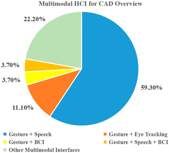
Figure 1. Survey on multimodal interfaces for CAD.
-
Different modalities can be used to execute different CAD commands. For example, in [48], eye tracking is used to select CAD models and gesture is used to activate different types of manipulation commands.
-
Different modalities can be used to execute the same CAD commands at the same time. In another words, there is overlap in the set of CAD commands that can be implemented through different modalities. For example, the task of creating models can be completed both by BCI-enabled commands and speech commands [3]. In this case, users can choose different interfaces according to their preferences. Moreover, to a certain extent, this kind of overlap in commands improves the robustness and flexibility of the interfaces.
-
Different modalities can be combined to execute a CAD command synergistically. In this respect, the advantages of different interfaces can be leveraged to work together on a model manipulation task. For example, in most CAD prototype systems combined with speech and gesture [8][12][42], speech is used to activate specific model manipulation commands (translation, rotation, zooming, etc.), while gestures are used to control the magnitude and direction of specific manipulations.
3. Devices for Natural HCI
Although these interfaces are unlikely to completely replace traditional WIMP-based interfaces, the importance of multimodal natural HCIs is growing due to advances in hardware and software, the benefits that they can provide to users, and the natural fit with the increasingly ubiquitous mobile computing environment [92]. In the process of CAD modeling, signals that can represent the design intention should first be obtained to identify the user intention. Thus, signal acquisition and identification devices are important for achieving a natural HCI. In this section, the devices used for eye tracking, gesture recognition, speech recognition, and BCI are introduced in detail, as presented in Table 2. In additional, some other devices related to natural HCIs are also briefly described.Table 2. Overview of devices for natural HCIs.
| Signal Modalities | Categories | Devices |
|---|---|---|
| Eye tracking | Head-mounted | Dikablis Glass 3.0 [93], Tobii Glass 2 [94], Pupil Labs Glasses [95] |
| Tabletop | Gazepoint GP3 [96], Tobii Pro Spectrum 150 [97], EyeLink 1000 Plus [98] | |
| Gesture | Sensor-based | MoCap Pro Glove [99], Cyber Glove [100], Vrtrix Glove [101] |
| Vision-based | Kinect [102], Leap Motion [20][103] | |
| Speech | DP-100 Connected Speech Recognition System (CSRS) [41], Microsoft Speech API (SAPI) [31], CMUSphinx [104] | |
| EEG | Saline electrode | Emotiv Epoc+ [3][36] |
| Wet electrode | Neuroscan [34] | |
| Dry electrode | Neurosky MindWave [105], InteraXon Muse [106] | |
| Others | Haptic | SensAble PHANTom [107], SPIDAR [108] |
| VR/AR | HTC Vive [109], Oculus Rift [110], HoloLens 2 [111] | |
3.1. Devices for Eye Tracking
Eye tracking technology is used to track the eye movement state of the user and recognize where the user is looking on a computer screen through some advanced optical recognition methods, such as the pupil–corneal reflection method [112], pupillary-canthus method [113], HN method [114], and so on. The first eye-tracker that could measure eye movements quantitatively was developed by Dodge and Cline in 1901 [115]. With the dramatic improvement in eye-tracking technology, more advanced and easy-to-use hardware has been developed on the market in recent years [116]. Currently, there are two main categories of eye-trackers available as interactive input devices, including head-mounted devices and tabletop devices. The head-mounted eye-tracker, which usually needs to be attached to the eyes as special contact lenses or headsets, is composed of a scene camera, which records the user’s first-person view, and an eye camera, which continuously records the changes of the sight line by using the infrared ray of cornea and pupil reflection [117]. Some common commercial head-mounted eye-trackers can be used for HCIs, as shown in Figure 2. Obviously, these head-mounted devices are inconvenient and involve some physical load for users. Therefore, the lightweight design of head-mounted eye-trackers is needed to make them more widely used in natural HCIs.

3.2. Devices for Gesture Recognition
Gesture recognition involves algorithms to detect and recognize the movement of fingers, palms, arms, or the entire body so as to interpret the user’s interaction intent. Currently, the devices for gesture recognition can be broadly divided into sensor-based devices, such as data gloves, and vision-based devices, such as normal video cameras or depth-aware cameras. Sensor-based devices can directly capture the motion and position of hand gesture by using data gloves. Commonly used sensors mainly include EMG sensors [118], bending sensors [119], pressure sensors [120], and acceleration sensors [121]. By using these glove sensors, researchers can easily obtain various gesture signals and accurately identify the hand pose and movement. Representative products in data gloves for gesture recognition are MoCap Pro Glove, Cyber Glove, and Vrtrix Glove, as shown in Figure 4. However, these data gloves are too expensive and their wired sensors restrict natural hand movement [23]. To overcome these limitations, the vision-based approach came into existence [74].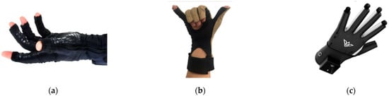

3.3. Devices for Speech Recognition
Speech recognition-based interfaces provide a natural method to operate and modify the CAD models for users. Along with the development of signal input devices and natural language-processing technology, the accuracy and effectiveness of speech recognition has been significantly improved, which further promotes the application of speech-based interfaces for CAD. Generally, the devices for speech recognition consist of two main modules, i.e., an input microphone and speech recognition module. After converting the analog signal with speech information into a digital signal through the input microphone, the speech recognition module integrated with natural language-processing algorithms completes the final recognition of semantics [123]. Obviously, the speech recognition module is a cord part of this system as an internal algorithm processor. Additionally, many companies have developed a variety of speech-recognition modules. For example, NEC (Nippon Electric Company) developed a system called DP-100 Connected Speech Recognition System (CSRS) [41] which is able to recognize a limited number of connect voices without pause. Microsoft also introduced its own voice-recognition interface for computers, Microsoft Speech API (SAPI) [31]. Carnegie Mellon University developed a speech-recognition toolbox, CMUSphinx, that can be used for microphone speech recognition [104]. In addition, machine learning and deep learning algorithms such as the Hidden Markov Model (HMM) [124], Convolutional Neural Network (CNN) [125] and Long Short-term Memory (LSTM) [126] have been widely used in the core part of speech recognition modules to improve the accuracy of speech recognition.3.4. Devices for EEG Acquisition
The EEG acquisition device is a piece of equipment that can record the electrical activity of the brain through some specific electrodes placed on a user’s scalp [127]. In 1924, the first EEG detection device in the world was developed by Berger in Jena, Germany [128]. Following the development of signal processing and microelectronics technology, the structure and function of EEG-acquisition devices have gradually matured. There are numerous EEG devices from different companies that are able to cater to the specific needs of EEG users, such as Neuroscan, Emotiv, and Neurosky MindWave. Generally, EEG-acquisition devices can be divided into invasive, semi-invasive, and non-invasive categories according to the connection with the brain [129]. Among them, a non-invasive EEG device is mainly used in the area of natural HCIs due to the damage of the scalp caused by the invasive device and the semi-invasive device. For non-invasive EEG devices, the types of electrodes used can be categorized into saline electrode, wet electrode, and dry electrode [129]. Saline electrodes use salt water as a conductive medium, which is easy to carry and low in cost [130]. Wet electrodes usually need to use gel as a conductive medium and can collect high-quality EEG signals. Dry electrodes can directly contact the user’s scalp to achieve conduction without any conductive medium which is more natural and convenient to the user, but the signal acquisition accuracy is limited [131]. In current studies in the literature, Emotiv Epoc+ is commonly used as an EEG-acquisition device in the application of CAD [3][35][36][37]. Emotiv Epoc+ is a small and low-cost device used to record and recognize EEG and facial muscles’ movements (EMG) with 14 saline electrodes. This device can communicate wirelessly with computer via a USB dongle and provide the Emotiv API, a C++ API, which can be used to easily obtain the EEG/EMG data and transform the user-specific action command into an easy-to-user structure [3]. Additionally, some other lightweight and low-cost EEG devices, such as Neurosky MindWave and InteraXon Muse, may also be used to build future BCI for CAD.3.5. Other Devices for Natural HCI
In addition to the main devices mentioned above, some other devices for natural HCIs are briefly introduced in this part. A haptic device is an interaction device which can deliver force feedback to a user, while interacting with the virtual environment (VE) or real environment (RE) [132]. This device could provide a more realistic interaction experience by making users feel the movement and touch the interaction models. The SensAble PHANTom [107][133][134] is one of the most common haptic devices used in CAD applications, which consists of a mechanical robotic arm with joints and a pen-shaped end-effector as manipulator. The arm follows the movement of the manipulator and is capable of generating a force equivalent to that applied to the manipulator [10]. Additionally, the wearable haptic device, SPIDAR, is also used to interact with virtual mock-ups [108]. Compared to SensAble PHANTom, SPIDAR has a more flexible workspace and allows the user to grasp the virtual models with natural experience. From the studies of [10][53][132], haptic devices are always applied in a virtual environment (VR) for CAD. In another word, VR devices are also needed and important for natural HCIs of CAD. Currently, the most popular VR/AR devices on the market are HTC Vive, Oculus Rift, HoloLens, and so on, as shown in Figure 6. Additionally, some other interactive devices such as touchscreen and EMG-based devices, are not listed here due to their limited application in the area of CAD.
References
- Allen, J.; Kouppas, P. Computer Aided Design: Past, Present, Future. In Design and Designing: A Critical Introduction; BERG: London, UK, 2012; pp. 97–111.
- Bilgin, M.S.; Baytaroğlu, E.N.; Erdem, A.; Dilber, E. A Review of Computer-Aided Design/Computer-Aided Manufacture Techniques for Removable Denture Fabrication. Eur. J. Dent. 2016, 10, 286–291.
- Nanjundaswamy, V.G.; Kulkarni, A.; Chen, Z.; Jaiswal, P.; Verma, A.; Rai, R. Intuitive 3D Computer-Aided Design (CAD) System with Multimodal Interfaces. In Proceedings of the 33rd Computers and Information in Engineering Conference, Portland, OR, USA, 4–7 August 2013; ASME: New York, NY, USA, 2013; Volume 2A, p. V02AT02A037.
- Wu, K.C.; Fernando, T. Novel Interface for Future CAD Environments. In Proceedings of the 2004 IEEE International Conference on Systems, Man and Cybernetics, The Hague, The Netherlands, 10–13 October 2004; Volume 7, pp. 6286–6290.
- Huang, J.; Rai, R. Conceptual Three-Dimensional Modeling Using Intuitive Gesture-Based Midair Three-Dimensional Sketching Technique. J. Comput. Inf. Sci. Eng. 2018, 18, 041014.
- Ryu, K.; Lee, J.J.; Park, J.M. GG Interaction: A Gaze–Grasp Pose Interaction for 3D Virtual Object Selection. J. Multimodal User Interfaces 2019, 13, 383–393.
- Vuletic, T.; Duffy, A.; McTeague, C.; Hay, L.; Brisco, R.; Campbell, G.; Grealy, M. A Novel User-Based Gesture Vocabulary for Conceptual Design. Int. J. Hum. Comput. Stud. 2021, 150, 102609.
- Friedrich, M.; Langer, S.; Frey, F. Combining Gesture and Voice Control for Mid-Air Manipulation of CAD Models in VR Environments. In Proceedings of the VISIGRAPP 2021—16th International Joint Conference on Computer Vision, Imaging and Computer Graphics Theory and Applications, Online, 8–10 February 2021; Volume 2, pp. 119–127.
- Huang, Y.-C.; Chen, K.-L. Brain-Computer Interfaces (BCI) Based 3D Computer-Aided Design (CAD): To Improve the Efficiency of 3D Modeling for New Users. In Lecture Notes in Computer Science (Including Subseries Lecture Notes in Artificial Intelligence and Lecture Notes in Bioinformatics); Schmorrow, D.D., Fidopiastis, C.M., Eds.; Springer International Publishing: Cham, Switzerland, 2017; Volume 10285, pp. 333–344.
- Toma, M.-I.; Postelnicu, C.; Antonya, C. Multi-Modal Interaction for 3D Modeling. Bull. Transilv. Univ. Brasov. Eng. Sci. 2010, 3, 137–144.
- Khan, S.; Tunçer, B.; Subramanian, R.; Blessing, L. 3D CAD Modeling Using Gestures and Speech: Investigating CAD Legacy and Non-Legacy Procedures. In Proceedings of the “Hello, Culture”—18th International Conference on Computer-Aided Architectural Design Future (CAAD Future 2019), Daejeon, Korea, 26–28 June 2019; pp. 624–643.
- Khan, S.; Tunçer, B. Gesture and Speech Elicitation for 3D CAD Modeling in Conceptual Design. Autom. Constr. 2019, 106, 102847.
- Jowers, I.; Prats, M.; McKay, A.; Garner, S. Evaluating an Eye Tracking Interface for a Two-Dimensional Sketch Editor. Comput. Des. 2013, 45, 923–936.
- Yoon, S.M.; Graf, H. Eye Tracking Based Interaction with 3d Reconstructed Objects. In Proceeding of the 16th ACM International Conference on Multimedia—MM ’08, Vancouver, BC, Canada, 27–31 October 2008; ACM Press: New York, NY, USA, 2008; p. 841.
- Argelaguet, F.; Andujar, C. A Survey of 3D Object Selection Techniques for Virtual Environments. Comput. Graph. 2013, 37, 121–136.
- Thakur, A.; Rai, R. User Study of Hand Gestures for Gesture Based 3D CAD Modeling. In Proceedings of the ASME Design Engineering Technical Conference, Boston, MA, USA, 2–5 August 2015; Volume 1B-2015, pp. 1–14.
- Esquivel, J.C.R.; Viveros, A.M.; Perry, N. Gestures for Interaction between the Software CATIA and the Human via Microsoft Kinect. In International Conference on Human-Computer Interaction; Springer: Berlin/Heidelberg, Germany, 2014; pp. 457–462.
- Dave, D.; Chowriappa, A.; Kesavadas, T. Gesture Interface for 3d Cad Modeling Using Kinect. Comput. Aided. Des. Appl. 2013, 10, 663–669.
- Zhong, K.; Kang, J.; Qin, S.; Wang, H. Rapid 3D Conceptual Design Based on Hand Gesture. In Proceedings of the 2011 3rd International Conference on Advanced Computer Control, Harbin, China, 18–20 January 2011; pp. 192–197.
- Xiao, Y.; Peng, Q. A Hand Gesture-Based Interface for Design Review Using Leap Motion Controller. In Proceedings of the 21st International Conference on Engineering Design (ICED 17), Vancouver, BC, Canada, 21–25 August 2017; Volume 8, pp. 239–248.
- Vinayak; Murugappan, S.; Liu, H.; Ramani, K. Shape-It-Up: Hand Gesture Based Creative Expression of 3D Shapes Using Intelligent Generalized Cylinders. CAD Comput. Aided Des. 2013, 45, 277–287.
- Vinayak; Ramani, K. A Gesture-Free Geometric Approach for Mid-Air Expression of Design Intent in 3D Virtual Pottery. CAD Comput. Aided Des. 2015, 69, 11–24.
- Huang, J.; Rai, R. Hand Gesture Based Intuitive CAD Interface. In Proceedings of the ASME 2014 International Design Engineering Technical Conferences and Computers and Information in Engineering Conference, Buffalo, NY, USA, 17–20 August 2014.
- Kou, X.Y.; Xue, S.K.; Tan, S.T. Knowledge-Guided Inference for Voice-Enabled CAD. Comput. Des. 2010, 42, 545–557.
- Kou, X.Y.; Liu, X.C.; Tan, S.T. Quadtree Based Mouse Trajectory Analysis for Efficacy Evaluation of Voice-Enabled CAD. In Proceedings of the 2009 IEEE International Conference on Virtual Environments, Human-Computer Interfaces and Measurements Systems, Hong Kong, China, 1–13 May 2009; pp. 196–201.
- Samad, T.; Director, S.W. Towards a Natural Language Interface for CAD. In Proceedings of the 22nd ACM/IEEE Design Automation Conference, Las Vegas, NV, USA, 23–26 June 1985; pp. 2–8.
- Salisbury, M.W.; Hendrickson, J.H.; Lammers, T.L.; Fu, C.; Moody, S.A. Talk and Draw: Bundling Speech and Graphics. Computer 1990, 23, 59–65.
- Kou, X.Y.; Tan, S.T. Design by Talking with Computers. Comput. Aided. Des. Appl. 2008, 5, 266–277.
- Menegotto, J.L. A Framework for Speech-Oriented CAD and BIM Systems. In Communications in Computer and Information Science; Springer: Berlin/Heidelberg, Germany, 2015; Volume 527, pp. 329–347.
- Behera, A.K.; McKay, A. Designs That Talk and Listen: Integrating Functional Information Using Voice-Enabled CAD Systems. In Proceedings of the 25th European Signal Processing Conference, Kos, Greek, 28 August–2 September 2017.
- Xue, S.; Kou, X.Y.; Tan, S.T. Natural Voice-Enabled CAD: Modeling via Natural Discourse. Comput. Aided. Des. Appl. 2009, 6, 125–136.
- Plumed, R.; González-Lluch, C.; Pérez-López, D.; Contero, M.; Camba, J.D. A Voice-Based Annotation System for Collaborative Computer-Aided Design. J. Comput. Des. Eng. 2021, 8, 536–546.
- Sree Shankar, S.; Rai, R. Human Factors Study on the Usage of BCI Headset for 3D CAD Modeling. Comput. Des. 2014, 54, 51–55.
- Trejo, L.J.; Rosipal, R.; Matthews, B. Brain-Computer Interfaces for 1-D and 2-D Cursor Control: Designs Using Volitional Control of the EEG Spectrum or Steady-State Visual Evoked Potentials. IEEE Trans. Neural Syst. Rehabil. Eng. 2006, 14, 225–229.
- Esfahani, E.T.; Sundararajan, V. Using Brain Computer Interfaces for Geometry Selection in CAD Systems: P300 Detection Approach. In Proceedings of the 31st Computers and Information in Engineering Conference, Parts A and B, Washington, DC, USA, 28–31 August 2011; Volume 2, pp. 1575–1580.
- Esfahani, E.T.; Sundararajan, V. Classification of Primitive Shapes Using Brain-Computer Interfaces. CAD Comput. Aided Des. 2012, 44, 1011–1019.
- Huang, Y.C.; Chen, K.L.; Wu, M.Y.; Tu, Y.W.; Huang, S.C.C. Brain-Computer Interface Approach to Computer-Aided Design: Rotate and Zoom in/out in 3ds Max via Imagination. In Proceedings of the International Conferences Interfaces and Human Computer Interaction 2015 (IHCI 2015), Los Angeles, CA, USA, 2–7 August 2015; Game and Entertainment Technologies 2015 (GET 2015), Las Palmas de Gran Canaria, Spain, 22–24 July 2015, Computer Graphics, Visualization, Computer Vision and Image Processing 2015 (CGVCVIP 2015), Las Palmas de Gran Canaria, Spain, 22–24 July 2015. pp. 319–322.
- Postelnicu, C.; Duguleana, M.; Garbacia, F.; Talaba, D. Towards P300 Based Brain Computer Interface for Computer Aided Design. In Proceedings of the 11th EuroVR 2014, Bremen, Germany, 8–10 December 2014; pp. 2–6.
- Verma, A.; Rai, R. Creating by Imagining: Use of Natural and Intuitive BCI in 3D CAD Modeling. In Proceedings of the 33rd Computers and Information in Engineering Conference, Portland, OR, USA, 4–7 August 2013; American Society of Mechanical Engineers: New York, NY, USA, 2013; Volume 2A.
- Moustakas, K.; Tzovaras, D. MASTER-PIECE: A Multimodal (Gesture + Speech) Interface for 3D Model Search and Retrieval Integrated in a Virtual Assembly Application. In Proceedings of the eINTERFACE′05-Summer Workshop on Multimodal Interfaces, Mons, Belgium, 12–18 August 2005; pp. 1–14.
- Bolt, R.A. Put-That-There. In Proceedings of the 7th Annual Conference on Computer Graphics and Interactive Techniques—SIGGRAPH ’80, Seattle, WA, USA, 14–18 July 1980; ACM Press: New York, NY, USA, 1980; pp. 262–270.
- Khan, S.; Rajapakse, H.; Zhang, H.; Nanayakkara, S.; Tuncer, B.; Blessing, L. GesCAD: An Intuitive Interface for Conceptual Architectural Design. In Proceedings of the 29th Australian Conference on Computer-Human Interaction, Brisbane, Australia, 28 November–1 December 2017; ACM: New York, NY, USA, 2017; pp. 402–406.
- Hauptmann, A.G. Speech and Gestures for Graphic Image Manipulation. ACM SIGCHI Bull. 1989, 20, 241–245.
- Arangarasan, R.; Gadh, R. Geometric Modeling and Collaborative Design in a Multi-Modal Multi-Sensory Virtual Environment. In Proceedings of the ASME 2000 International Design Engineering Technical Conferences and Computers and Information in Engineering Conference, Baltimore, MD, USA, 10–13 September 2000; pp. 10–13.
- Chu, C.-C.P.; Dani, T.H.; Gadh, R. Multi-Sensory User Interface for a Virtual-Reality-Based Computeraided Design System. Comput. Des. 1997, 29, 709–725.
- Chu, C.-C.P.; Dani, T.H.; Gadh, R. Multimodal Interface for a Virtual Reality Based Computer Aided Design System. In Proceedings of the International Conference on Robotics and Automation, Albuquerque, NM, USA, 20–25 April 1997; Volume 2, pp. 1329–1334.
- Song, J.; Cho, S.; Baek, S.Y.; Lee, K.; Bang, H. GaFinC: Gaze and Finger Control Interface for 3D Model Manipulation in CAD Application. CAD Comput. Aided Des. 2014, 46, 239–245.
- Pouke, M.; Karhu, A.; Hickey, S.; Arhippainen, L. Gaze Tracking and Non-Touch Gesture Based Interaction Method for Mobile 3D Virtual Spaces. In Proceedings of the 24th Australian Computer-Human Interaction Conference on OzCHI ’12, Melbourne, Australia, 26–30 November 2012; ACM Press: New York, NY, USA, 2012; pp. 505–512.
- Shafiei, S.B.; Esfahani, E.T. Aligning Brain Activity and Sketch in Multi-Modal CAD Interface. In Proceedings of the ASME 2014 International Design Engineering Technical Conferences and Computers and Information in Engineering Conference, Buffalo, NY, USA, 17–20 August 2014; Volume 1A, pp. 1–7.
- Bhat, R.; Deshpande, A.; Rai, R.; Esfahani, E.T. BCI-Touch Based System: A Multimodal CAD Interface for Object Manipulation. In Volume 12: Systems and Design, Proceedings of the ASME 2013 International Mechanical Engineering Congress and Exposition, San Diego, CA, USA, 15–21 November 2013; American Society of Mechanical Engineers: New York, NY, USA, 2013; p. V012T13A015.
- Sharma, A.; Madhvanath, S. MozArt: A Multimodal Interface for Conceptual 3D Modeling. In Proceedings of the 13th International Conference on Multimodal Interfaces, Alicante, Spain, 14–18 November 2011; pp. 3–6.
- Bourdot, P.; Convard, T.; Picon, F.; Ammi, M.; Touraine, D.; Vézien, J.-M. VR–CAD Integration: Multimodal Immersive Interaction and Advanced Haptic Paradigms for Implicit Edition of CAD Models. Comput. Des. 2010, 42, 445–461.
- Mogan, G.; Talaba, D.; Girbacia, F.; Butnaru, T.; Sisca, S.; Aron, C. A Generic Multimodal Interface for Design and Manufacturing Applications. In Proceedings of the 2nd International Workshop Virtual Manufacturing (VirMan08), Torino, Italy, 6–8 October 2008.
- Stark, R.; Israel, J.H.; Wöhler, T. Towards Hybrid Modelling Environments—Merging Desktop-CAD and Virtual Reality-Technologies. CIRP Ann.-Manuf. Technol. 2010, 59, 179–182.
- Ren, X.; Zhang, G.; Dai, G. An Experimental Study of Input Modes for Multimodal Human-Computer Interaction. In Proceedings of the International Conference on Multimodal Interfaces, Beijing, China, 14–16 October 2000; Volume 1, pp. 49–56.
- Jaimes, A.; Sebe, N. Multimodal Human–Computer Interaction: A Survey. Comput. Vis. Image Underst. 2007, 108, 116–134.
- Hutchinson, T.E. Eye-Gaze Computer Interfaces: Computers That Sense Eye Position on the Display. Computer 1993, 26, 65–66.
- Sharma, C.; Dubey, S.K. Analysis of Eye Tracking Techniques in Usability and HCI Perspective. In Proceedings of the 2014 International Conference on Computing for Sustainable Global Development (INDIACom), New Delhi, India, 5–7 March 2014; pp. 607–612.
- Brooks, R.; Meltzoff, A.N. The Development of Gaze Following and Its Relation to Language. Dev. Sci. 2005, 8, 535–543.
- Duchowski, A.T. A Breadth-First Survey of Eye-Tracking Applications. Behav. Res. Methods Instrum. Comput. 2002, 34, 455–470.
- Kumar, M.; Paepcke, A.; Winograd, T. Eyepoint: Practical Pointing and Selection Using Gaze and Keyboard. In Proceedings of the SIGCHI Conference on Human Factors in Computing Systems, San Jose, CA, USA, 28 April–3 May 2007; pp. 421–430.
- Majaranta, P.; Räihä, K.-J. Twenty Years of Eye Typing: Systems and Design Issues. In Proceedings of the 2002 Symposium on Eye Tracking Research & Applications, New Orleans, LA, USA, 25–27 March 2002; pp. 15–22.
- Wobbrock, J.O.; Rubinstein, J.; Sawyer, M.W.; Duchowski, A.T. Longitudinal Evaluation of Discrete Consecutive Gaze Gestures for Text Entry. In Proceedings of the 2008 Symposium on Eye Tracking Research & Applications, Savannah, GA, USA, 26–28 March 2008; pp. 11–18.
- Hornof, A.J.; Cavender, A. EyeDraw: Enabling Children with Severe Motor Impairments to Draw with Their Eyes. In Proceedings of the SIGCHI Conference on Human Factors in Computing Systems, Portland, OR, USA, 2–7 April 2005; pp. 161–170.
- Wu, C.-I. HCI and Eye Tracking Technology for Learning Effect. Procedia-Soc. Behav. Sci. 2012, 64, 626–632.
- Hekele, F.; Spilski, J.; Bender, S.; Lachmann, T. Remote Vocational Learning Opportunities—A Comparative Eye-Tracking Investigation of Educational 2D Videos versus 360° Videos for Car Mechanics. Br. J. Educ. Technol. 2022, 53, 248–268.
- Dickie, C.; Vertegaal, R.; Sohn, C.; Cheng, D. EyeLook: Using Attention to Facilitate Mobile Media Consumption. In Proceedings of the 18th Annual ACM Symposium on User Interface Software and Technology, Seattle, WA, USA, 23–26 October 2005; pp. 103–106.
- Nagamatsu, T.; Yamamoto, M.; Sato, H. MobiGaze: Development of a Gaze Interface for Handheld Mobile Devices. In Proceedings of the Human Factors in Computing Systems, New York, NY, USA, 10–15 April 2010; pp. 3349–3354.
- Miluzzo, E.; Wang, T.; Campbell, A.T. Eyephone: Activating Mobile Phones with Your Eyes. In Proceedings of the Second ACM SIGCOMM Workshop on Networking, Systems, and Applications on Mobile Handhelds, New Delhi, India, 30 August 2010; pp. 15–20.
- Lee, H.; Lim, S.Y.; Lee, I.; Cha, J.; Cho, D.-C.; Cho, S. Multi-Modal User Interaction Method Based on Gaze Tracking and Gesture Recognition. Signal Process. Image Commun. 2013, 28, 114–126.
- Franslin, N.M.F.; Ng, G.W. Vision-Based Dynamic Hand Gesture Recognition Techniques and Applications: A Review. In Proceedings of the 8th International Conference on Computational Science and Technology, Labuan, Malaysia, 28–29 August 2021; Springer: Berlin/Heidelberg, Germany, 2022; pp. 125–138.
- Tumkor, S.; Esche, S.K.; Chassapis, C. Hand Gestures in CAD Systems. In Proceedings of the Asme International Mechanical Engineering Congress and Exposition, San Diego, CA, USA, 15–21 November 2013; American Society of Mechanical Engineers: New York, NY, USA, 2013; Volume 56413, p. V012T13A008.
- Florin, G.; Butnariu, S. Design Review of Cad Models Using a NUI Leap Motion Sensor. J. Ind. Des. Eng. Graph. 2015, 10, 21–24.
- Kaur, H.; Rani, J. A Review: Study of Various Techniques of Hand Gesture Recognition. In Proceedings of the 1st IEEE International Conference on Power Electronics, Intelligent Control and Energy Systems, ICPEICES 2016, Delhi, India, 4–6 July 2016; IEEE: Piscataway, NJ, USA, 2017; pp. 1–5.
- Fuge, M.; Yumer, M.E.; Orbay, G.; Kara, L.B. Conceptual Design and Modification of Freeform Surfaces Using Dual Shape Representations in Augmented Reality Environments. CAD Comput. Aided Des. 2012, 44, 1020–1032.
- Pareek, S.; Sharma, V.; Esfahani, E.T. Human Factor Study in Gesture Based Cad Environment. In Proceedings of the International Design Engineering Technical Conferences and Computers and Information in Engineering Conference, Boston, MA, USA, 2–5 August 2015; Volume 1B-2015, pp. 1–6.
- Huang, J.; Jaiswal, P.; Rai, R. Gesture-Based System for next Generation Natural and Intuitive Interfaces. In Artificial Intelligence for Engineering Design, Analysis and Manufacturing-AIEDAM; Cambridge University Press: Cambridge, UK, 2019; Volume 33, pp. 54–68.
- Clark, L.; Doyle, P.; Garaialde, D.; Gilmartin, E.; Schlögl, S.; Edlund, J.; Aylett, M.; Cabral, J.; Munteanu, C.; Edwards, J.; et al. The State of Speech in HCI: Trends, Themes and Challenges. Interact. Comput. 2019, 31, 349–371.
- Gao, S.; Wan, H.; Peng, Q. Approach to Solid Modeling in a Semi-Immersive Virtual Environment. Comput. Graph. 2000, 24, 191–202.
- Rezeika, A.; Benda, M.; Stawicki, P.; Gembler, F.; Saboor, A.; Volosyak, I. Brain–Computer Interface Spellers: A Review. Brain Sci. 2018, 8, 57.
- Amiri, S.; Fazel-Rezai, R.; Asadpour, V. A Review of Hybrid Brain-Computer Interface Systems. Adv. Hum.-Comput. Interact. 2013, 2013, 187024.
- Pfurtscheller, G.; Leeb, R.; Keinrath, C.; Friedman, D.; Neuper, C.; Guger, C.; Slater, M. Walking from Thought. Brain Res. 2006, 1071, 145–152.
- Lécuyer, A.; Lotte, F.; Reilly, R.B.; Leeb, R.; Hirose, M.; Slater, M. Brain-Computer Interfaces, Virtual Reality, and Videogames. Computer 2008, 41, 66–72.
- Zhao, Q.; Zhang, L.; Cichocki, A. EEG-Based Asynchronous BCI Control of a Car in 3D Virtual Reality Environments. Chin. Sci. Bull. 2009, 54, 78–87.
- Li, Y.; Wang, C.; Zhang, H.; Guan, C. An EEG-Based BCI System for 2D Cursor Control. In Proceedings of the 2008 IEEE International Joint Conference on Neural Networks (IEEE World Congress on Computational Intelligence), Hong Kong, China, 1–6 June 2008; pp. 2214–2219.
- Chun, J.; Bae, B.; Jo, S. BCI Based Hybrid Interface for 3D Object Control in Virtual Reality. In Proceedings of the 4th International Winter Conference on Brain-Computer Interface—BCI 2016, Gangwon, Korea, 22–24 February 2016; pp. 19–22.
- Esfahani, E.T.; Sundararajan, V. Using Brain–Computer Interfaces to Detect Human Satisfaction in Human–Robot Interaction. Int. J. Hum. Robot. 2011, 8, 87–101.
- Turk, M. Multimodal Interaction: A Review. Pattern Recognit. Lett. 2014, 36, 189–195.
- Sebe, N. Multimodal Interfaces: Challenges and Perspectives. J. Ambient Intell. Smart Environ. 2009, 1, 23–30.
- Jaímes, A.; Sebe, N. Multimodal Human Computer Interaction: A Survey. In Lecture Notes in Computer Science (Including Subseries Lecture Notes in Artificial Intelligence and Lecture Notes in Bioinformatics); Figure 1; Springer: Berlin/Heidelberg, Germany, 2005; Volume 3766, pp. 1–15.
- Dumas, B.; Lalanne, D.; Oviatt, S. Multimodal Interfaces: A Survey of Principles, Models and Frameworks; Springer: Berlin/Heidelberg, Germany, 2009; pp. 3–26.
- Cutugno, F.; Leano, V.A.; Rinaldi, R.; Mignini, G. Multimodal Framework for Mobile Interaction. In Proceedings of the International Working Conference on Advanced Visual Interfaces, Capri Island, Italy, 21–25 May 2012; pp. 197–203.
- Ergoneers Dikablis Glasses 3 Eye Tracker. Available online: https://www.jalimedical.com/dikablis-glasses-eye-tracker.php (accessed on 10 May 2020).
- Tobii Pro Glasses 2—Discontinued. Available online: https://www.tobiipro.com/product-listing/tobii-pro-glasses-2/ (accessed on 10 May 2020).
- Pupil Labs Core Hardware Specifications. Available online: https://imotions.com/hardware/pupil-labs-glasses/ (accessed on 10 May 2020).
- GP3 Eye Tracker. Available online: https://www.gazept.com/product/gazepoint-gp3-eye-tracker/ (accessed on 10 May 2020).
- Tobii Pro Spectrum. Available online: https://www.tobiipro.com/product-listing/tobii-pro-spectrum/ (accessed on 10 May 2020).
- EyeLink 1000 Plus. Available online: https://www.sr-research.com/eyelink-1000-plus/ (accessed on 10 May 2020).
- MoCap Pro Gloves. Available online: https://stretchsense.com/solution/gloves/ (accessed on 10 May 2020).
- CyberGlove Systems. Available online: http://www.cyberglovesystems.com/ (accessed on 10 May 2020).
- VRTRIX. Available online: http://www.vrtrix.com/ (accessed on 10 May 2020).
- Kinect from Wikipedia. Available online: https://en.wikipedia.org/wiki/Kinect (accessed on 10 May 2020).
- Leap Motion Controller. Available online: https://www.ultraleap.com/product/leap-motion-controller/ (accessed on 10 May 2020).
- Satori, H.; Harti, M.; Chenfour, N. Introduction to Arabic Speech Recognition Using CMUSphinx System. arXiv 2007, arXiv0704.2083.
- NeuroSky. Available online: https://store.neurosky.com/ (accessed on 10 May 2020).
- Muse (Headband) from Wikipedia. Available online: https://en.wikipedia.org/wiki/Muse_(headband) (accessed on 10 May 2020).
- Liu, X.; Dodds, G.; McCartney, J.; Hinds, B.K. Manipulation of CAD Surface Models with Haptics Based on Shape Control Functions. CAD Comput. Aided Des. 2005, 37, 1447–1458.
- Chamaret, D.; Ullah, S.; Richard, P.; Naud, M. Integration and Evaluation of Haptic Feedbacks: From CAD Models to Virtual Prototyping. Int. J. Interact. Des. Manuf. 2010, 4, 87–94.
- VIVE Pro 2. Available online: https://www.vive.com/us/product/vive-pro2-full-kit/overview/ (accessed on 10 May 2020).
- Meta Quest. Available online: https://www.oculus.com/rift-s/ (accessed on 10 May 2020).
- Microsoft HoloLens 2. Available online: https://www.microsoft.com/en-us/hololens (accessed on 10 May 2020).
- Sigut, J.; Sidha, S.-A. Iris Center Corneal Reflection Method for Gaze Tracking Using Visible Light. IEEE Trans. Biomed. Eng. 2010, 58, 411–419.
- Chennamma, H.R.; Yuan, X. A Survey on Eye-Gaze Tracking Techniques. Indian J. Comput. Sci. Eng. 2013, 4, 388–393.
- Ma, C.; Baek, S.-J.; Choi, K.-A.; Ko, S.-J. Improved Remote Gaze Estimation Using Corneal Reflection-Adaptive Geometric Transforms. Opt. Eng. 2014, 53, 53112.
- Dodge, R.; Cline, T.S. The Angle Velocity of Eye Movements. Psychol. Rev. 1901, 8, 145.
- Stuart, S.; Hickey, A.; Vitorio, R.; Welman, K.; Foo, S.; Keen, D.; Godfrey, A. Eye-Tracker Algorithms to Detect Saccades during Static and Dynamic Tasks: A Structured Review. Physiol. Meas. 2019, 40, 02TR01.
- Chen, C.H.; Monroy, C.; Houston, D.M.; Yu, C. Using Head-Mounted Eye-Trackers to Study Sensory-Motor Dynamics of Coordinated Attention, 1st ed.; Elsevier: Amsterdam, The Netherlands, 2020; Volume 254.
- Lake, S.; Bailey, M.; Grant, A. Method and Apparatus for Analyzing Capacitive Emg and Imu Sensor Signals for Gesture Control. U.S. Patents 9,299,248, 29 March 2016.
- Wang, Z.; Cao, J.; Liu, J.; Zhao, Z. Design of Human-Computer Interaction Control System Based on Hand-Gesture Recognition. In Proceedings of the 2017 32nd Youth Academic Annual Conference of Chinese Association of Automation (YAC), Hefei, China, 19–21 May 2017; pp. 143–147.
- Grosshauser, T. Low Force Pressure Measurement: Pressure Sensor Matrices for Gesture Analysis, Stiffness Recognition and Augmented Instruments. In Proceedings of the NIME 2008, Genova, Italy, 5–7 June 2008; pp. 97–102.
- Sawada, H.; Hashimoto, S. Gesture Recognition Using an Acceleration Sensor and Its Application to Musical Performance Control. Electron. Commun. Jpn. 1997, 80, 9–17.
- Suarez, J.; Murphy, R.R. Hand Gesture Recognition with Depth Images: A Review. In Proceedings of the 2012 IEEE RO-MAN: The 21st IEEE International Symposium on Robot and Human Interactive Communication, Paris, France, 9–13 September 2012; Volume 2012, pp. 411–417.
- Abu Shariah, M.A.M.; Ainon, R.N.; Zainuddin, R.; Khalifa, O.O. Human Computer Interaction Using Isolated-Words Speech Recognition Technology. In Proceedings of the ICIAS 2007: International Conference on Intelligent and Advanced Systems, Kuala Lumpur, Malaysia, 25–28 November 2007; pp. 1173–1178.
- Zhang, J.; Zhang, M. A Speech Recognition System Based Improved Algorithm of Dual-Template HMM. Procedia Eng. 2011, 15, 2286–2290.
- Chang, S.-Y.; Morgan, N. Robust CNN-Based Speech Recognition with Gabor Filter Kernels. In Proceedings of the Fifteenth Annual Conference of the International Speech Communication Association, Singapore, 14–18 September 2014.
- Soltau, H.; Liao, H.; Sak, H. Neural Speech Recognizer: Acoustic-to-Word LSTM Model for Large Vocabulary Speech Recognition. arXiv 2016, arXiv1610.09975.
- Tyagi, A. A Review of Eeg Sensors Used for Data Acquisition. Electron. Instrum. 2012, 13–18. Available online: https://www.researchgate.net/profile/Sunil-Semwal/publication/308259085_A_Review_of_Eeg_Sensors_used_for_Data_Acquisition/links/57df321408ae72d72eac238e/A-Review-of-Eeg-Sensors-used-for-Data-Acquisition.pdf (accessed on 10 May 2020).
- Pinegger, A.; Wriessnegger, S.C.; Faller, J.; Müller-Putz, G.R. Evaluation of Different EEG Acquisition Systems Concerning Their Suitability for Building a Brain–Computer Interface: Case Studies. Front. Neurosci. 2016, 10, 441.
- Zerafa, R.; Camilleri, T.; Falzon, O.; Camilleri, K.P. A Comparison of a Broad Range of EEG Acquisition Devices–Is There Any Difference for SSVEP BCIs? Brain-Comput. Interfaces 2018, 5, 121–131.
- Liu, Y.; Jiang, X.; Cao, T.; Wan, F.; Mak, P.U.; Mak, P.-I.; Vai, M.I. Implementation of SSVEP Based BCI with Emotiv EPOC. In Proceedings of the 2012 IEEE International Conference on Virtual Environments Human-Computer Interfaces and Measurement Systems (VECIMS), Tianjin, China, 2–4 July 2012; pp. 34–37.
- Guger, C.; Krausz, G.; Allison, B.Z.; Edlinger, G. Comparison of Dry and Gel Based Electrodes for P300 Brain–Computer Interfaces. Front. Neurosci. 2012, 6, 60.
- Kind, S.; Geiger, A.; Kießling, N.; Schmitz, M.; Stark, R. Haptic Interaction in Virtual Reality Environments for Manual Assembly Validation. Procedia CIRP 2020, 91, 802–807.
- Hirose, S. A VR Three-Dimensional Pottery Design System Using PHANTOM Haptic Devices. In Proceedings of the 4th PHANToM Users Group Workshop, Dedham, MA, USA, 9–12 October 1999.
- Nikolakis, G.; Tzovaras, D.; Moustakidis, S.; Strintzis, M.G. CyberGrasp and PHANTOM Integration: Enhanced Haptic Access for Visually Impaired Users. In Proceedings of the SPECOM’2004 9th Conference Speech and Computer, Saint-Petersburg, Russia, 20–22 September 2004; pp. x1–x7.
More