Your browser does not fully support modern features. Please upgrade for a smoother experience.
Please note this is a comparison between Version 2 by Guangtao Shang and Version 3 by Camila Xu.
Simultaneous Localization and Mapping (SLAM)AM was first applied in the field of robotics. Its goal is to build a real-time map of the surrounding environment based on sensor data without any prior knowledge, and at the same time predict its own location based on the map. SLAM has attracted extensive attention from many researchers since it was first proposed in 1986 and is now a necessary capability for autonomous mobile robots. In recent years, due to the rich environmental information that cameras can obtain, the research of vision-based SLAM has developed rapidly, and a series of amazing achievements have been made.
- SLAM
- computer vision
- Robot
- Environmental awareness
1. Introduction
SLAM [1] (Simultaneous Localization and Mapping), which enables localization and mapping in unfamiliar environments, has become a necessary capacity for autonomous mobile robots. Since it was first proposed in 1986, SLAM has attracted extensive attention from many researchers and developed rapidly in robotics, virtual reality, and other fields. SLAM refers to self-positioning based on location and map, and building incremental maps based on self-positioning. It is mainly used to solve the problem of robot localization and map construction when moving in an unknown environment [2].
2. Sensors Commonly Used in VSLAM
The sensors used in the VSLAM typically include the monocular camera, stereo camera, and RGB-D camera. The monocular camera and the stereo camera have similar principles and can be used in a wide range of indoor and outdoor environments. As a special form of camera, the RGB-D camera can directly obtain image depth mainly by actively emitting infrared structured light or calculating time-of-flight (TOF). It is convenient to use, but sensitive to light, and can only be used indoors in most cases [3]. Events camera as appeared in recent years, a new camera sensor, a picture of a different from the traditional camera. Events camera is “events”, can be as simple as “pixel brightness change”. The change of events camera output is pixel brightness, SLAM algorithm based on the event camera is still only in the preliminary study stage [4]. In Figure 13, rwesearchers compare the main features of different cameras.
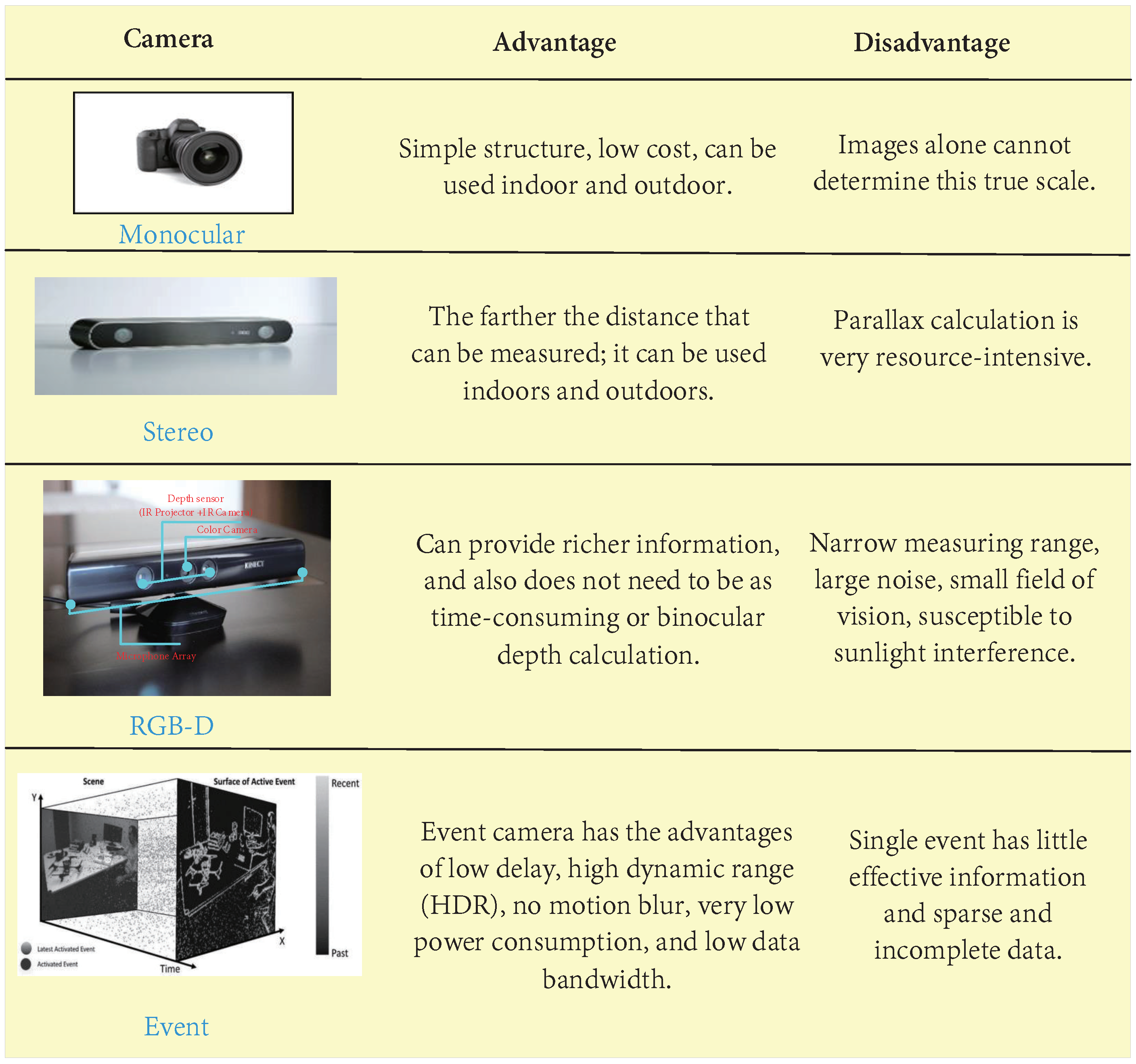
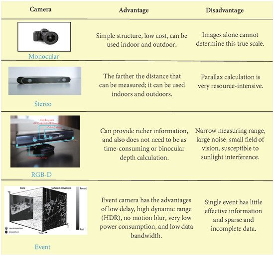
Figure 12. Comparison between different cameras. An event camera is not a specific type of camera, but a camera that can obtain “event information”. “Traditional cameras” work at a constant frequency and have natural drawbacks, such as lag, blurring, and overexposure when shooting high-speed objects. However, the event camera, a neuro-based method of processing information similar to the human eye, has none of these problems.
3. Traditional VSLAM
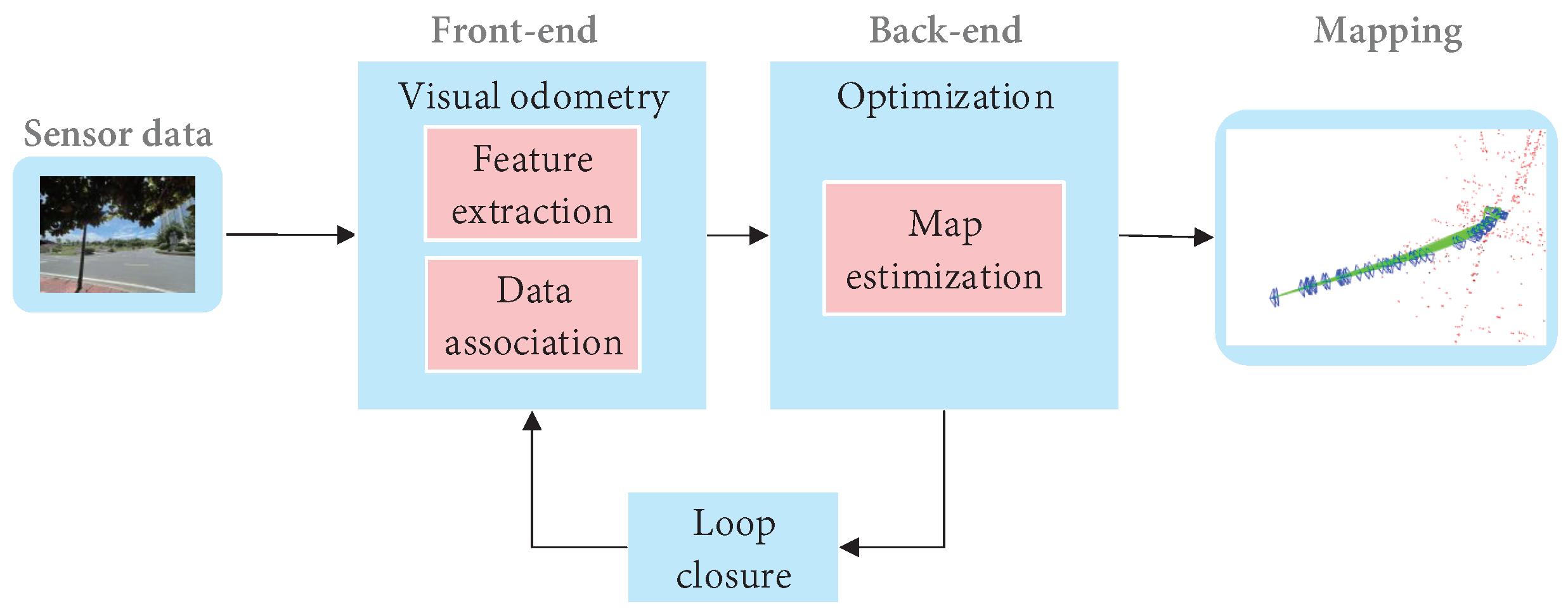
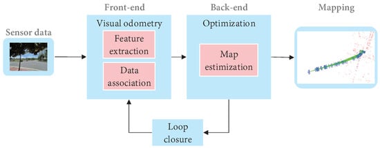
Cadena et al. [5] proposed a classical VSLAM framework, which mainly consists of two parts: front-end and back-end, as shown in Figure 23. The front end provides real-time camera pose estimation, while the back end provides map updates and optimizations. Specifically, mature visual SLAM systems include sensor data collection, front-end visual odometer, back-end optimization, loop closure detection, and map construction modules [6].
Figure 23. The typical visual SLAM system framework.
The typical visual SLAM system framework.
3.1 VSLAM Based on the Feature-Based Method
The core of indirect VSLAM is to detect, extract and match geometric features( points, lines, or planes), estimate camera pose, and build an environment map while retaining important information, it can effectively reduce calculation, so it has been widely used [7]. The VSLAM method based on point feature has long been taken into account as the mainstream method of indirect VSLAM due to its simplicity and practicality [8].
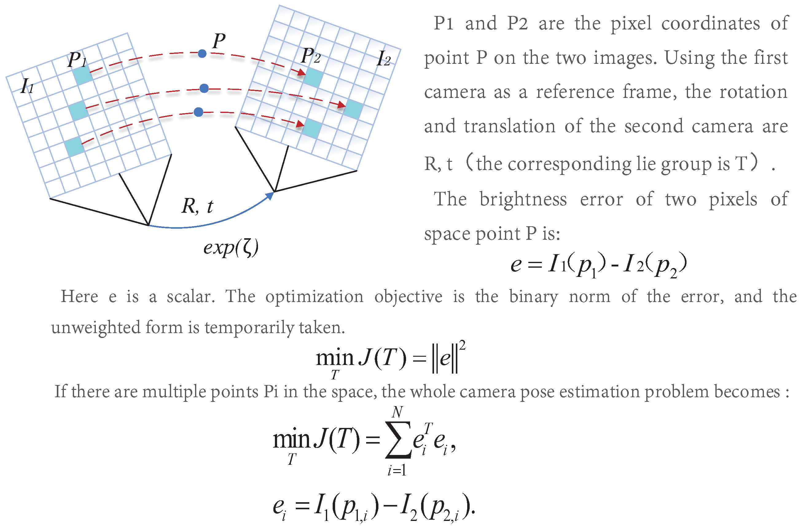
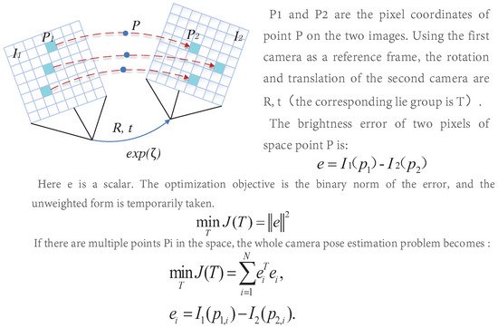
Different from feature-based methods, the direct method operates directly on pixel intensity and can retain all information about the image. Furthermore, the direct method cancels the process of feature extraction and matching, so the computational efficiency is better than the indirect method. Furthermore, it has good adaptability to the environment with complex textures. It can still keep a good effect in the environment with missing features. The direct method is similar to the optical flow, and they both have a strong assumption: gray-level invariance, the principle of which is shown in Figure 312.
Figure 312. Schematic diagram of the direct method.
Schematic diagram of the direct method.
3.2. RGB-D SLAM
An RGB-D camera is a visual sensor launched in recent years. The RGB-D camera, as a special camera, can gain three-dimensional information in space more conveniently. So it has been widely concerned and developed in three-dimensional reconstruction [9]. Although the RGB-D camera is more convenient to use, the RGB-D camera is extremely sensitive to light. Furthermore, there are many problems with narrow, noisy, and small horizons, so most of the situation is only used in the room. In addition, the existing algorithms must be implemented using GPU. So the mainstream traditional VSLAM system still does not use the RGB-D camera as the main sensor.
3.3. Visual-Inertial SLAM
IMU is considered to be one of the most complementary sensors to the camera. It can obtain accurate estimation at high frequency in a short time, and reduce the impact of dynamic objects on the camera. In addition, the camera data can effectively correct the cumulative drift of IMU [10]. At the same time, due to the miniaturization and cost reduction of cameras and IMU, visual-inertial fusion has also achieved rapid development. Nowadays, visual-inertial fusion can be divided into loosely coupled and tightly coupled according to whether image feature information is added to the state vector [11]. Loosely coupled means the IMU and the camera estimate their motion, respectively, and then fuse their pose estimation. Tightly coupled refers to the combination of the state of IMU and the state of the camera to jointly construct the equation of motion and observation, and then perform state estimation [12].
3.3.1. Loosely Coupled Visual-Inertial
The loosely coupled core is to fuse the positions and poses calculated by the vision sensor and IMU, respectively. The fusion has no impact on the results obtained by the two. Generally, the fusion is performed through EKF. The loose-coupling implementation is relatively simple, but the fusion result is prone to error and there has been little research in this area.
3.3.2. Tightly Coupled Visual-Inertial
The core of the tightly coupled is to combine the states of the vision sensor and IMU through an optimized filter. It needs the image features to be added to the feature vector to jointly construct the motion equation and observation equation [13]. Then perform state estimation to obtain the pose information. Tightly coupled needs full use of visual and inertial measurement information, which is complicated in method implementation but can achieve higher pose estimation accuracy. Therefore, it is also the mainstream method, and many breakthroughs have been made in this area.As a supplement to cameras, inertial sensors can effectively solve the problem that a single camera cannot cope with. Visual inertial fusion is bound to become a long-term hot direction of SLAM research [14].
References
- Khalid Yousif; Alireza Bab-Hadiashar; Reza Hoseinnezhad; An Overview to Visual Odometry and Visual SLAM: Applications to Mobile Robotics. Intelligent Industrial Systems 2015, 1, 289-311, 10.1007/s40903-015-0032-7.
- Andréa Macario Barros; Maugan Michel; Yoann Moline; Gwenolé Corre; Frédérick Carrel; A Comprehensive Survey of Visual SLAM Algorithms. Robotics 2022, 11, 24, 10.3390/robotics11010024.
- Ian De Medeiros Esper; Oleh Smolkin; Maksym Manko; Anton Popov; Pål Johan From; Alex Mason; Evaluation of RGB-D Multi-Camera Pose Estimation for 3D Reconstruction. Applied Sciences 2022, 12, 4134, 10.3390/app12094134.
- Thomas Whelan; Renato F Salas-Moreno; Ben Glocker; Andrew J Davison; Stefan Leutenegger; ElasticFusion: Real-time dense SLAM and light source estimation. The International Journal of Robotics Research 2016, 35, 1697-1716, 10.1177/0278364916669237.
- Cesar Cadena; Luca Carlone; Henry Carrillo; Yasir Latif; Davide Scaramuzza; Jose Neira; Ian Reid; John J. Leonard; Past, Present, and Future of Simultaneous Localization and Mapping: Toward the Robust-Perception Age. IEEE Transactions on Robotics 2016, 32, 1309-1332, 10.1109/tro.2016.2624754.
- Yi Zhou; Guillermo Gallego; Shaojie Shen; Event-Based Stereo Visual Odometry. IEEE Transactions on Robotics 2021, 37, 1433-1450, 10.1109/tro.2021.3062252.
- Rana Azzam; Tarek Taha; Shoudong Huang; Yahya Zweiri; Feature-based visual simultaneous localization and mapping: a survey. SN Applied Sciences 2020, 2, 1-24, 10.1007/s42452-020-2001-3.
- Ruihao Li; Sen Wang; Dongbing Gu; Ongoing Evolution of Visual SLAM from Geometry to Deep Learning: Challenges and Opportunities. Cognitive Computation 2018, 10, 875-889, 10.1007/s12559-018-9591-8.
- Hamid Taheri; Zhao Chun Xia; SLAM; definition and evolution. Engineering Applications of Artificial Intelligence 2020, 97, 104032, 10.1016/j.engappai.2020.104032.
- Tong Qin; Peiliang Li; Shaojie Shen; VINS-Mono: A Robust and Versatile Monocular Visual-Inertial State Estimator. IEEE Transactions on Robotics 2018, 34, 1004-1020, 10.1109/tro.2018.2853729.
- Stefan Leutenegger; Simon Lynen; Michael Bosse; Roland Siegwart; Paul Furgale; Keyframe-based visual–inertial odometry using nonlinear optimization. The International Journal of Robotics Research 2014, 34, 314-334, 10.1177/0278364914554813.
- Raul Mur-Artal; Juan D. Tardos; ORB-SLAM2: An Open-Source SLAM System for Monocular, Stereo, and RGB-D Cameras. IEEE Transactions on Robotics 2017, 33, 1255-1262, 10.1109/tro.2017.2705103.
- Andrew J. Davison; Ian D. Reid; Nicholas D. Molton; Olivier Stasse; MonoSLAM: Real-Time Single Camera SLAM. IEEE Transactions on Pattern Analysis and Machine Intelligence 2007, 29, 1052-1067, 10.1109/tpami.2007.1049.
- Yanjie Liu; Changsen Zhao; Meixuan Ren; An Enhanced Hybrid Visual–Inertial Odometry System for Indoor Mobile Robot. Sensors 2022, 22, 2930, 10.3390/s22082930.
More