Your browser does not fully support modern features. Please upgrade for a smoother experience.
Please note this is a comparison between Version 1 by Guangtao Shang and Version 3 by Camila Xu.
Simultaneous Localization and Mapping (SLAM) was first applied in the field of robotics. Its goal is to build a real-time map of the surrounding environment based on sensor data without any prior knowledge, and at the same time predict its own location based on the map. SLAM has attracted extensive attention from many researchers since it was first proposed in 1986 and is now a necessary capability for autonomous mobile robots.SLAM(同步定位和映射)可以在不熟悉的环境中进行定位和映射,已成为自主移动机器人的必要能力。自1986年首次提出以来,SLAM引起了许多研究人员的广泛关注,并在机器人,虚拟现实等领域迅速发展。SLAM是指基于位置和地图的自定位,以及基于自我定位的增量地图。它主要用于解决机器人在未知环境中移动时的定位和地图构建问题。SLAM作为一项基础技术,在前期就已经应用于移动机器人的定位和导航。
- SLAM
- computer vision
- Robot
- Environmental awareness
- deep learning
- neural networks
1. Introduction
People need the mobile robot to perform some tasks by themselves, which needs the robot to be able to adapt to an unfamiliar environment. Therefore, SLAM [1] (Simultaneous Localization and Mapping), which enables localization and mapping in unfamiliar environments, has become a necessary capacity for autonomous mobile robots. Since it was first proposed in 1986, SLAM has attracted extensive attention from many researchers and developed rapidly in robotics, virtual reality, and other fields. SLAM refers to self-positioning based on location and map, and building incremental maps based on self-positioning. It is mainly used to solve the problem of robot localization and map construction when moving in an unknown environment [2][2]. SLAM, as a basic technology, has been applied to mobile robot localization and navigation in the early stage. With the development of computer technology (hardware) and artificial intelligence (software), robot research has received more and more attention and investment. Numerous researchers are committed to making robots more intelligent. SLAM is considered to be the key to promoting the real autonomy of mobile robots [3].
Some scholars divide SLAM into Laser SLAM and Visual SLAM (VSLAM) according to the different sensors adopted [4]. Compared with VSLAM, because of an early start, laser SLAM studies abroad are relatively mature and have been considered the preferred solution for mobile robots for a long time in the past. Similar to human eyes, VSLAM mainly uses images as the information source of environmental perception, which is more consistent with human understanding and has more information than laser SLAM. In recent years, camera-based VSLAM research has attracted extensive attention from researchers. Due to the advantages of cheap, easy installation, abundant environmental information, and easy fusion with other sensors, many vision-based SLAM algorithms have emerged [5]. VSLAM has the advantage of richer environmental information and is considered to be able to give mobile robots stronger perceptual ability and be applied in some specific scenarios. Therefore, this paper focuses on VSLAM and combs out the algorithms derived from it. SLAM based on all kinds of laser radar is not within the scope of discussion in this paper. Interested readers can refer to [6,7,8] and other sources in the literature.
As one of the solutions for autonomous robot navigation, traditional VSLAM is essentially a simple environmental understanding based on image geometric features [9]. Because traditional VSLAM only uses the geometric feature of the environment, such as points and lines, to face this low-level geometry information, it can reach a high level in real-time. Facing changes in lighting, texture, and dynamic objects are widespread, which shows the obvious shortage, in terms of position precision and robustness is flawed [10]. Although the map constructed by traditional visual SLAM includes important information in the environment and meets the positioning needs of the robot to a certain extent. It is inadequate in supporting the autonomous navigation and obstacle avoidance tasks of the robot. Furthermore, it cannot meet the interaction needs of the intelligent robot with the environment and humans [11].
People’s demand for intelligent mobile robots is increasing day by day, which put forward a high need for autonomous ability and the human–computer interaction ability of robots [12]. The traditional VSLAM algorithm can meet the basic positioning and navigation requirements of the robot, but cannot complete higher-level tasks such as “help me close the bedroom door”, “go to the kitchen and get me an apple”, etc. To achieve such goals, robots need to recognize information about objects in the scene, find out their locations and build semantic maps. With the help of semantic information, the data association is upgraded from the traditional pixel level to the object level. Furthermore, the perceptual geometric environment information is assigned with semantic labels to obtain a high-level semantic map. It can help the robot to understand the autonomous environment and human–computer interaction [13]. We believe that the rapid development of deep learning provides a bridge for the introduction of semantic information into VSLAM. Especially in semantic map construction, combining it with VLAM can enable robots to gain high-level perception and understanding of the scene. It significantly improves the interaction ability between robots and the environment [14].
In 2016, Cadena et al. [15] first proposed to divide the development of SLAM into three stages. In their description, we are in a stage of robust perception, as shown in Figure 1. They describe the emphasis and contribution of SLAM in different times from three aspects: Classical, Algorithmic, and Robust. Ref. [16] summarizes the development of vision-based SLAM algorithms from 2010 to 2016 and provides a toolkit to help beginners. Yousif et al. [17] discussed the elementary framework of VSLAM and summarized several mathematical problems to help readers make the best choice. Bavle et al. [18] summarized the robot SLAM technology and pointed out the development trend of robot scene understanding. Starting from the fusion of vision and visual inertia, Servieres et al. [19] reviewed and compared important methods and summarized excellent algorithms emerging in SLAM. Azzam et al. [20] conducted a comprehensive study on feature-based methods. They classified the reviewed methods according to the visual features observed in the environment. Furthermore, they also proposed possible problems and solutions for the development of SLAM in the future. Ref. [21] introduces in detail the SLAM method based on monocular, binocular, RGB-D, and visual-inertial fusion, and gives the existing problems and future direction. Ref. [22] describes the opportunities and challenges of VSLAM from geometry to deep learning and forecasts the development prospects of VSLAM in the future semantic era.
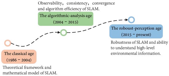
Figure 1. Overview of SLAM development era. The development of SLAM has gone through three main stages: theoretical framework, algorithm analysis, and advanced robust perception. The time points are not strictly limited, but rather represent the development of SLAM at a certain stage and the hot issues that people are interested in.
2. Sensors Commonly Used in VSLAM
The sensors used in the VSLAM typically include the monocular camera, stereo camera, and RGB-D camera. The monocular camera and the stereo camera have similar principles and can be used in a wide range of indoor and outdoor environments. As a special form of camera, the RGB-D camera can directly obtain image depth mainly by actively emitting infrared structured light or calculating time-of-flight (TOF). It is convenient to use, but sensitive to light, and can only be used indoors in most cases [3][23]. Events camera as appeared in recent years, a new camera sensor, a picture of a different from the traditional camera. Events camera is “events”, can be as simple as “pixel brightness change”. The change of events camera output is pixel brightness, SLAM algorithm based on the event camera is still only in the preliminary study stage [4][24]. In Figure 1addition, as researchers ca classical SLAM system based on vision, visual-inertial fusion has achieved excellent results in many aspects. In Figure 3, we compare the main features of different cameras.
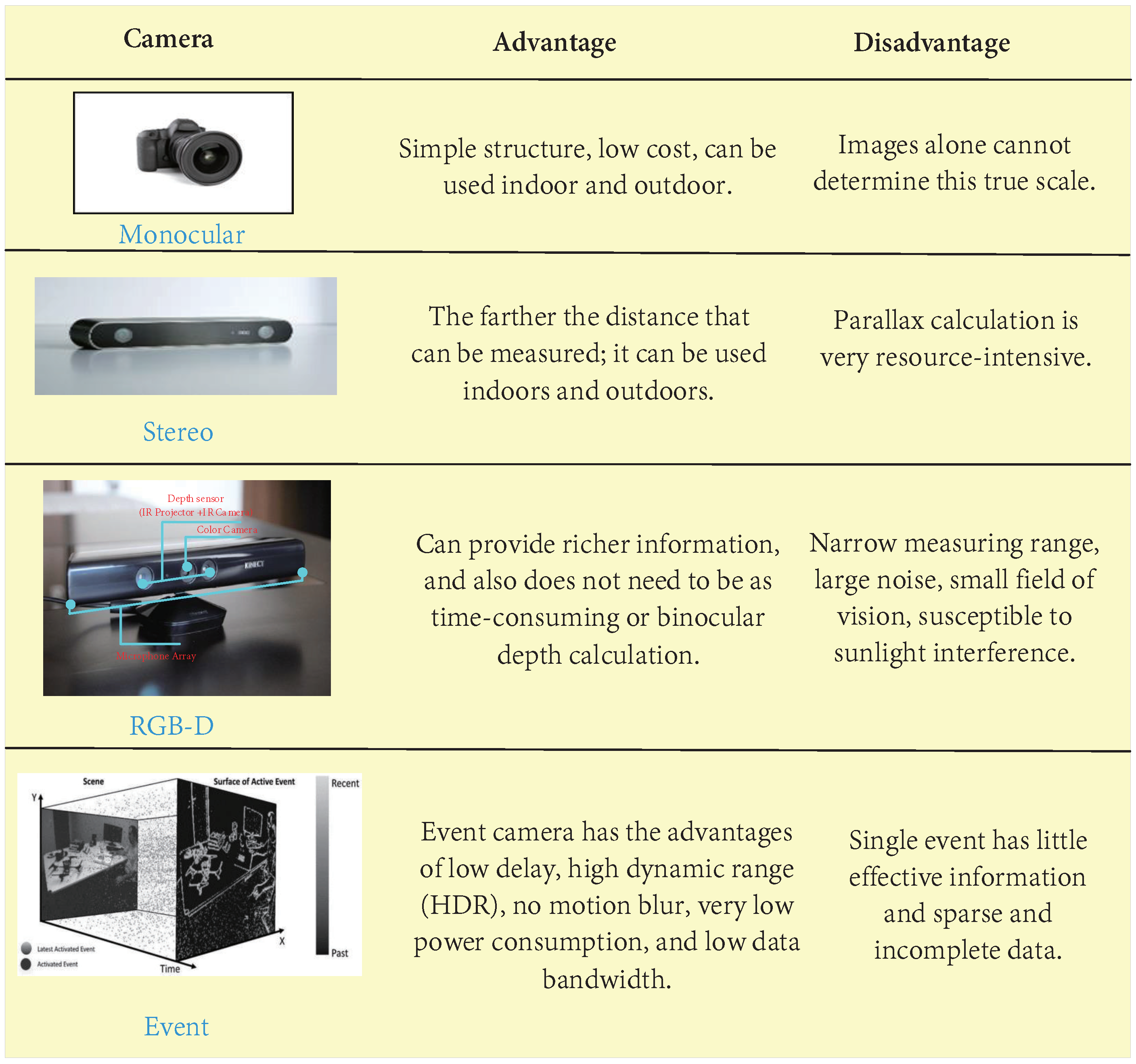
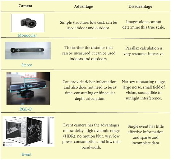
Figure 13. Comparison between different cameras. An event camera is not a specific type of camera, but a camera that can obtain “event information”. “Traditional cameras” work at a constant frequency and have natural drawbacks, such as lag, blurring, and overexposure when shooting high-speed objects. However, the event camera, a neuro-based method of processing information similar to the human eye, has none of these problems.
3. Traditional VSLAM
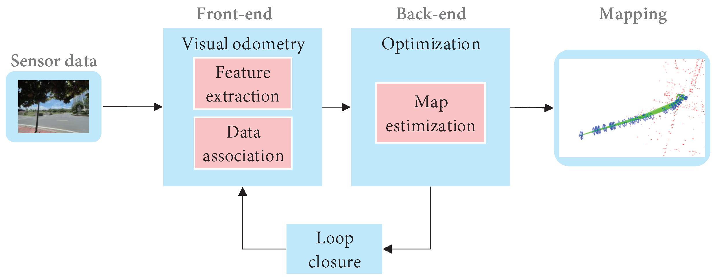
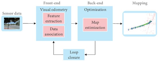
Cadena et al. [5][15] proposed a classical VSLAM framework, which mainly consists of two parts: front-end and back-end, as shown in Figure 29. The front end provides real-time camera pose estimation, while the back end provides map updates and optimizations. Specifically, mature visual SLAM systems include sensor data collection, front-end visual odometer, back-end optimization, loop closure detection, and map construction modules [6][64].
Figure 29. The typical visual SLAM system framework.
The typical visual SLAM system framework.
3.1 VSLAM Based on the Feature-Based Method
3.1. Monocular/Stereo VSLAM
In this section, we will elaborate on the VSLAM algorithm based on monocular or stereo cameras. For the VSLAM system, the visual odometer, as the front-end of SLAM, is an indispensable part [65]. Ref. [20] points out that VSLAM can be divided into the direct method and indirect method according to the different image information collected by the front-end visual odometer. The indirect method needs to select a certain number of representative points from the collected images, called key points, and detect and match them in the following images to gain the camera pose. It not only saves the key information of the image but also reduces the amount of calculation, so it is widely used. The direct method uses all the information of the image without preprocessing and directly operates on pixel intensity, which has higher robustness in an environment with sparse texture [66]. Both the indirect method and direct method have been widely concerned and developed to different degrees.
3.1.1. VSLAM Based on the Feature-Based Method
The core of indirect VSLAM is to detect, extract and match geometric features( points, lines, or planes), estimate camera pose, and build an environment map while retaining important information, it can effectively reduce calculation, so it has been widely used [7][67]. The VSLAM method based on point feature has long been taken into account as the mainstream method of indirect VSLAM due to its simplicity and practicality [8][68].
Feature extraction mostly adopted corner extraction methods in the early, such as Harris [69], FAST [70], GFTT [71], etc. However, in many scenarios, simple corners cannot provide reliable features, which prompts researchers to seek more stable local image features. Nowadays, typical VSLAM methods based on point features firstly use feature detection algorithms, such as SIFT [72], SURF [73], and ORB [74], to extract key points in the image for matching. Then gain pose after minimizing reprojection error. Feature points and corresponding descriptors in the image are employed for data association. Furthermore, data association in initialization is completed through the matching of feature descriptors [75]. In Table 3, we list common traditional feature extraction algorithms and compare their main performance to help readers have a more comprehensive understanding.
Table 3. Comparison table of commonly used feature extraction algorithms.
| Method | Year | Type | Speed | Rotation Invariance | Scale Invariance | Illumination Invariance | Anti-Invariance |
|---|---|---|---|---|---|---|---|
| ORB [74] | 2011 | Point | High | Yes | Yes | Yes | Stronger |
| SURF [73] | 2008 | Point | Middle | Yes | Yes | No | Week |
| FAST [70] | 2006 | Point | High | No | Yes | No | Week |
| SIFT [72] | 2004 | Point | Low | Yes | Yes | Yes | Strong |
| Shi-Tomasi [71] | 1994 | Coner | Middle | Yes | No | Yes | Week |
| Harris [69] | 1988 | Coner | Low | Yes | No | Yes | Week |
| LSD [76] | 2010 | Line | Middle | Yes | Yes | Yes | Stronger |
Davidson et al. [77] proposed MonoSLAM in 2007. This algorithm is considered to be the first real-time monocular VSLAM algorithm, which can achieve real-time drift free-motion structure recovery. The front end tracks the sparse feature points shi-Tomasi corner point for feature point matching, and the back end uses Extended Kalman Filter (EKF) [78] for optimization, which can build the sparse environment map online in real-time. This algorithm has a milestone significance in SLAM research, but the EKF method leads to a square growth between storage and state quantity, so it is not suitable for large-scale scenarios. In the same year, the advent of PTAM [79] improved MonoSLAM’s inability to work steadily for long periods in a wide range of environments. PTAM, as the first SLAM algorithm using nonlinear optimization at the back end, solves the problem of fast data growth in the filter-based method. Furthermore, it separated tracking and mapping into two different threads for the first time. The front end uses FAST corner detection to extract and estimate camera motion using image features, and the back end is responsible for nonlinear optimization and mapping. It not only ensures the real-time performance of SLAM in the calculation of camera pose but also ensures the accuracy of the whole SLAM system. However, because there is no loopback detection module, it will accumulate errors during long-running.
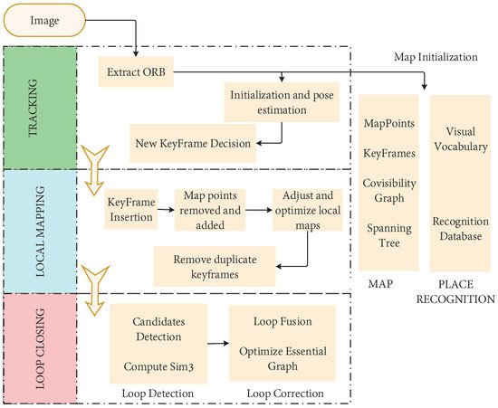
In 2015, MUR-Artal et al. proposed the ORB-SLAM [80]. This algorithm is regarded as the excellent successor of PTAM, and based on PTAM, added a loop closure detection module, which effectively reduces the cumulative error. As a real-time monocular visual SLAM system that uses ORB feature matching, the whole process is carried out around ORB features. As shown in Figure 10, the three threads of tracking, local mapping, and loop closure detection are used innovatively. In addition, the loop closure detection thread uses the word bag model DBoW [81] for loop closure. The loop closure method based on the BoW model can detect the loop closure quickly by detecting the image similarity. Furthermore, achieve good results in the processing speed and the accuracy of map construction. In later years, the team launched ORB-SLAM2 [28] and ORB-SlAM3 [82]. The ORB-SLAM family is one of the most widely used visual SLAM solutions due to its real-time CPU performance and robustness. However, the ORB-SLAM series relies heavily on environmental features, so it may be difficult to obtain enough feature points in an environment without texture features.
Figure 10. Flow chart of ORB-SLAM.
The point feature-based SLAM system relies too much on the quality and quantity of point features. It is difficult to detect enough feature points in weak texture scenes, such as corridors, windows, white walls, etc. Thus, affecting the robustness and accuracy of the system and even leading to tracking failure. In addition, due to the rapid movement of the camera, illumination changes, and other reasons, the matching quantity and quality of point features will decline seriously. To improve the feature-based SLAM algorithms, the application of line features in SLAM systems has attracted more and more attention [83]. The commonly used line feature extraction algorithm is LSD [76].
In recent years, with the improvement of computer computing capacity, VSLAM-based online features have also been developed rapidly. Smith et al. [84] proposed a monocular VSLAM algorithm-based online feature extraction in 2006. Lines are represented by two endpoints, and line features are used in the SLAM system to detect and track the two endpoints of lines in small scenes. The system can use line features alone or in combination with point-line features, which is of groundbreaking significance in VSLAM research. In 2014, Perdices et al. proposed LineSLAM, a line-based monocular SLAM algorithm [85]. For line extraction, this scheme adopts the line extraction scheme in [86]. It detects the lines every time the keyframes are acquired. Then uses the Unscented Kalman Filter (UKF) to predict the current camera state and vector probability distribution of the ground line. Then, matches the line prediction result with the detected lines. Because the scheme has no loop closure and the line segment is of infinite length instead of finite length, it is difficult to be used in practice.
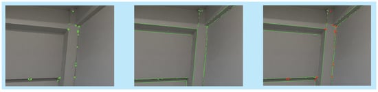
As shown in Figure 11, compared with point feature or line feature alone, the combination of point feature and line feature increases the number of feature observations and data association. Furthermore, line feature is less sensitive to light changes than the point feature, which improves the positioning accuracy and robustness of the original system [76]. In 2016, Klein et al. [87] adopted the method of point-line fusion to improve the tracking failure of the SLAM system due to image blur caused by fast camera movement. In 2017, Pumarola et al. [88] published monocular PL-SLAM, and Gomez-Ojeda et al. [89] published stereo PL-SLAM in the same year. Based on ORB-SLAM, the two algorithms use the LSD detection algorithm to detect line features and then combine the point-line features in each link of SLAM. It can work even when most of the point features disappear. Furthermore, it improves the accuracy, robustness, and stability of the SLAM system, but the real-time performance is not good.
Figure 11. Comparison of point and line feature extraction in a weak texture environment. From left to right are ORB point feature extraction, LSD line feature extraction, and point-line combination feature extraction.
In addition, in some environments, there are some obvious surface features, which have aroused great interest of some researchers. Ref. [90] proposed a map construction method combining planes and lines. By introducing surface features into the real-time VSLAM system, the errors are reduced and the system robustness is improved by combining low-level features. In 2017, Li et al. [91] proposed a VSLAM algorithm based on point, line, and plane fusion for an artificial environment. Point features are used for the initial estimation of the robot’s current pose. Lines and planes are used to describe the environment. However, most planes only exist in the artificial environment, and few suitable planes can be found in the natural environment. These limit its application range.
Compared with the methods that rely only on point features, SLAM systems that rely only on lines or planes can only work stably in artificial environments in most cases. The VSLAM method combining point, line, and surface features improve the localization accuracy and robustness in weak texture scenes, illumination changes, and fast camera movement. However, the introduction of line and surface features increases the time consumption of feature extraction and matching, which reduces the efficiency of the SLAM system. Therefore, the VSLAM algorithm based on the point feature still occupies the mainstream position [92]. Table 4 shows a comparison of geometric features.
Table 4. Comparison table of geometric features.
| Feature | Benefits | Disbenefits |
|---|---|---|
| Point | Is the most popular and commonly used feature, easy to store and match, and the speed is generally faster. | It is difficult to extract sufficient features in an environment of intense light and rapid camera rotation. |
| Line | It has natural lighting and viewing Angle invariance, while more advanced features also improve tracking robustness and accuracy. Especially in certain artificial scenes (indoor, corridor), the interference of untextured or unreliable textures can be overcome. | The detection and matching time of the line segment is longer than that of the feature point. There is also no standard, universal SLAM optimization and loopback module on the back end. Line feature matching is also difficult, for example, line segments are easy to fracture, do not have strong geometric constraints (such as polar line geometric constraints), and do not have strong identification of texture missing places. |
| Plane | It has a more stable effect in artificial environments. | The range is small and can only be operated in certain artificial environments. |
3.1.2. VSLAM Based on Direct Method
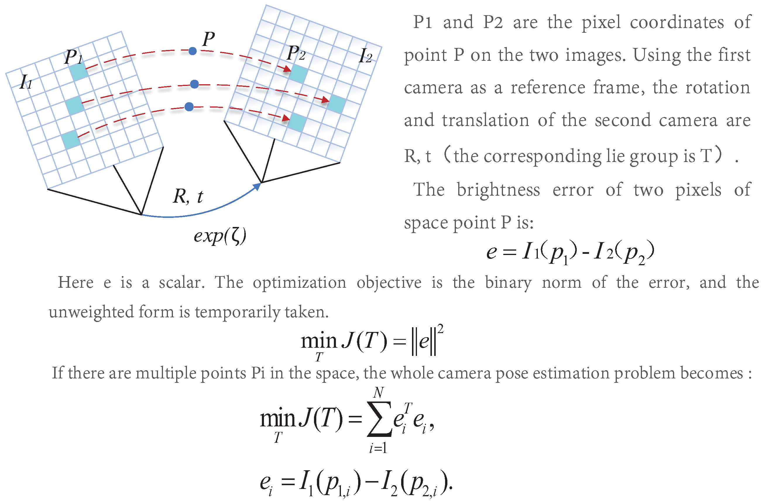
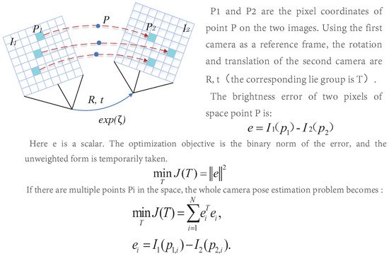
Different from feature-based methods, the direct method operates directly on pixel intensity and can retain all information about the image. Furthermore, the direct method cancels the process of feature extraction and matching, so the computational efficiency is better than the indirect method. Furthermore, it has good adaptability to the environment with complex textures. It can still keep a good effect in the environment with missing features [93]. The direct method is similar to the optical flow, and they both have a strong assumption: gray-level invariance, the principle of which is shown in Figure 312.
Figure 312. Schematic diagram of the direct method.
Schematic diagram of the direct method.
3.2. RGB-D SLAM
In 2011, Newcombe et al. [94] proposed the DTAM algorithm, which was considered the first practical direct method sof VSLAM. DTAM allows tracking by comparing the input images with those created by reconstructed maps. The algorithm performs a precise and detailed reconstruction of the environment. However, it affects the computational cost of storing and processing the data, so it can only run in real-time on GPU. LSD-SLAM [40] neglects texture-free areas to improve operational efficiency and can run in real-time on CUP. LSD-SLAM, another major approach indirect method, combines featureless extraction with semi-dense reconstruction, and its core is a visual odometer using semi-dense reconstruction. The algorithm consists of three steps: tracking, depth estimation, and map optimization. Firstly, the photometric error is minimized to estimate the sensor pose. Secondly, select a keyframe for in-depth estimation. Finally, in the map optimization step, the new keyframe is merged into the map and optimized by using the posture optimization algorithm. In 2014, Forster et al. [95] proposed the semi-direct visual SLAM algorithm SVO. Since the algorithm does not need to extract features for each frame, it can run at high frame rates, which enables it to run in low-cost embedded systems [80]. SVO combines the advantages of the feature point method and direct method. The algorithm is divided into two main threads: motion estimation and mapping. Motion estimation is carried out by feature point matching, but mapping is carried out by the direct method. SVO has good results, but as a purely visual method, it only performs short-term data association, which limits its accuracy [82]. In 2018, Engel et al. [39] proposed DSO. DSO can effectively use any image pixel, which makes it robust even in featureless regions and can gain more accurate results than SVO. DSO can calculate accurate camera attitude in poor feature point detector performance, improving the robustness of low-texture areas or blurred images. In addition, the DSO uses both geometric and photometric camera calibration results for high accuracy estimation. However, DSO only considers local geometric consistency, so it inevitably produces cumulative errors. Furthermore, it is not a complete SLAM because it does not include loop closure, map reuse, etc.
Up to now, VSLAM has made many achievements in direct and indirect methods. Table 5 compares the advantages and disadvantages of the direct method and the indirect method to help readers better understand.
Table 5. Comparison between direct method and indirect method.
| Method | Benefits | Shortcomings |
|---|---|---|
| Indirect | (1) The feature point itself is not sensitive to light, motion, and rotation, so it is relatively stable. (2) The camera moves faster (relatively direct method) and can track successfully, with better robustness. (3) The research time is long and the scheme is mature. | (1) It takes a long time to extract, describe and match key points. (2) The feature point loss scenario cannot be used. (3) Only sparse maps can be constructed. |
| Direct | (1) Fast speed, can save the calculation of feature points, and descriptors time. (2) It can be used in situations where features are missing (such as white walls), and the feature point method will deteriorate rapidly in this case. (3) Semi-dense and even dense maps can be constructed. | (1) Since the gray level is assumed to be unchanged, it is susceptible to the change in illumination. (2) Slow camera movement or high sampling frequency is required (can be improved by image pyramid). (3) The differentiation of single-pixel or pixel blocks is not strong, and the strategy of quantity instead of quality is adopted. |
3.2. RGB-D SLAM
An RGB-D camera is a visual sensor launched in recent years. It Tcan simultaneously collect environmental color images and depth images, and directly gain depth maps mainly by actively emitting infrared structured light or calculating time-of-flight (TOF) [96]. The RGB-D camera, as a special camera, can gain three-dimensional information in space more conveniently. So it has been widely concerned and developed in three-dimensional reconstruction [9][97].
KinectFusion [98] is the first real-time 3D reconstruction system based on an RGB-D camera. It uses a point cloud created by the depth to estimate the camera pose through ICP (Iterative Closest Point). Then splices multi-frame point cloud collection based on the camera pose, and expresses reconstruction result by the TSDF (Truncated signed distance Function) model. The 3D model can be constructed in real-time with GPU acceleration. However, the system has not been optimized by loop closure. Furthermore, there will be obvious errors in long-term operation, and the RGB information of the RGB-D camera has not been fully utilized. In contrast, ElasticFusion [27] makes full use of the color and depth information of the RGB-D camera. It estimates the camera pose by the color consistency of RGB and estimates the camera pose by ICP. Then improves the estimation accuracy of the camera pose by constantly optimizing and reconstructing the map. Finally, the surfel model was used for map representation, but it could only be reconstructed in a small indoor scene. Kinitinuous [99] adds loop closure based on KinectFusion and makes non-rigid body transformation for 3d rigid body reconstruction by using a deformation graph for the first time. So it makes the results of two-loop closure reconstruction overlap, achieving good results in an indoor environment. Compared with the above algorithms, RGB-D SLAMv2 [53] is a very excellent and comprehensive system. It includes image feature detection, optimization, loop closure, and other modules, which are suitable for beginners to carry out secondary development.
Although the RGB-D camera is more convenient to use, the RGB-D camera is extremely sensitive to light. Furthermore, there are many problems with narrow, noisy, and small horizons, so most of the situation is only used in the room. In addition, the existing algorithms must be implemented using GPU. So the mainstream traditional VSLAM system still does not use the RGB-D camera as the main sensor. However, in three-dimensional reconstruction in the interior, the RGB-D camera is widely used. In addition, because of the ability to build a dense environment map, the semantic VSLAM direction, RGB-D camera is widely used. Table 6 shows the classic SLAM algorithm based on RGB-D cameras.
Table 6. Some SLAM algorithms for sensors with an RGB-D camera.
| Method | Year | Camera Tracking | Loop Closure | Code Resource |
|---|---|---|---|---|
3.3.2. Tightly Coupled Visual-Inertial
The core of the tightly coupled is to combine the states of the vision sensor and IMU through an optimized filter. It needs the image features to be added to the feature vector to jointly construct the motion equation and observation equation [13]. Then perform state estimation to obtain the pose information. Tightly coupled needs full use of visual and inertial measurement information, which is complicated in method implementation but can achieve higher pose estimation accuracy. Therefore, it is also the mainstream method, and many breakthroughs have been made in this area.
In 2007, Mourikis et al. [117] proposed MSCKF. The core of MSCKF is to fuse IMU and visual information under the EKF in a tightly coupled way. Compared with the VO algorithm alone, MSCKF can adapt to more intense motion and texture loss, with higher robustness. Speed and accuracy can also reach a high level. MSCKF has been widely used in robot, UAV, and AR/VR fields a suppleme. However, because the backend uses the Kalman filter method, global information cannot be used for optimization, and no loopback detection will cause error accumulation. Ref. [29] proposed OKVIS based on a fusion of binocular vision and IMU. However, it to cameras, inertial sensors only outputs six degrees of freedom pose without loopback detection and map, so it is not a complete SLAM in a strict sense. Although it has good accuracy, its pose will be loose when it runs for a long time. Although these two algorithms have achieved good results, they have not been widely promoted. The lack of loop closure modules inevitably leads to cumulative errors when running for long periods of time.
The emergence of VINS-Mono [55] broke this situation effectively solve the problem that a single camera cannot cope with. In 2018, a team from The Hong Kong University of Science and Technology (HKUST) introduced a monocular inertially tightly coupled VINS-Mono algorithm. It has since released its expanded version, Vins-Fusion, which supports multi-sensor integration, including Monocular + IMU, Stereo + IMU, and even stereo only, and also provides a version with GPS. VINS-mono is a classic fusion of vision and IMU. Its positioning accuracy is comparable to OKVIS, and it has a more complete and robust initialization and loop closure detection process than OKVIS. At the same time, VINS-Mono has set a standard for the research and application of visual SLAM, which is more monocular +IMU. In the navigation of robots, especially the autonomous navigation of UAVs, monocular cameras are not limited by RGB-D cameras (susceptible to illumination and limited depth information) and stereo cameras (occupying a large space). It can adapt to indoor, outdoor and different illumination environments with good adaptability.
As a supplement to cameras, inertial sensors can effectively solve the problem that a single camera cannot cope with. Visual inertial fusion is bound to become a long-term hot direction of SLAM research. [14]However, the introduction of multiple sensors will lead to an increase in data, which has a high requirement on computing capacity [118]. Therefore, we believe that the next hot issue of visual-inertial fusion will be reflected in the efficient processing of sensor fusion data. How to make better use of data from different sensors will be a long-term attractive hot issue. Due to the rich information acquisition, convenient use and low price of visual sensors, the environment map constructed is closer to the real environment recognized by human beings. After decades of development, vision-based SLAM technology has achieved many excellent achievements. Table 7 summarizes some of the best visual-based SLAM algorithms, comparing their performance in key areas, and providing open-source addresses to help readers make better choices.
Table 7. Best visual-based SLAM algorithms.
| 方法 | 传感器 | 前端 | 后端 | 闭环 | 映射 | 代码资源 | |||||
|---|---|---|---|---|---|---|---|---|---|---|---|
| KinectFusion [98] | 2011 | Direct | No | [100] | |||||||
| 单色 [77] | M | P | F | 不 | 稀疏 | [119] | Kinitinuous [99] | 2012 | Direct | ||
| Yes | 断续器 [79] | M | P | [101] | |||||||
| O | 不 | 稀疏 | [120] | RGB-D SLAMv2 [53] | 2013 | Indirect | Yes | ||||
| ORB-SLAM2 [28] | [ | M/S/R | 102 | P | ] | ||||||
| O | 是的 | 稀疏 | [121] | ElasticFusion [27] | 2016 | Direct | Yes | ||||
| PL-SVO [ | [103] | ||||||||||
| 122 | ] | M | 断续器 | O | 不 | 稀疏 | [123] | DVO-SLAM [104] | 2017 | Direct | Yes |
| 视觉 | PL-灌篮 [88 | [105] | |||||||||
| ] | 米/秒 | 断续器 | O | 是的 | 稀疏 | [124] | BundleFusion [106] | 2017 | Hybrid | Yes | [107] |
| RGBDTAM [108] | 2017 | Direct | Yes | [109] |
3.3. Visual-Inertial SLAM
The pure visual SLAM algorithm has achieved many achievements. However, it is still difficult to solve the effects of image blur caused by fast camera movement and poor illumination by using only the camera as a single sensor [110]. IMU is considered to be one of the most complementary sensors to the camera. It can obtain accurate estimation at high frequency in a short time, and reduce the impact of dynamic objects on the camera. In addition, the camera data can effectively correct the cumulative drift of IMU [10][111]. At the same time, due to the miniaturization and cost reduction of cameras and IMU, visual-inertial fusion has also achieved rapid development. Furthermore, it become the preferred method of sensor fusion, which is favored by many researchers [112]. Nowadays, visual-inertial fusion can be divided into loosely coupled and tightly coupled according to whether image feature information is added to the state vector [11][113]. Loosely coupled means the IMU and the camera estimate their motion, respectively, and then fuse their pose estimation. Tightly coupled refers to the combination of the state of IMU and the state of the camera to jointly construct the equation of motion and observation, and then perform state estimation [12][114].
3.3.1. Loosely Coupled Visual-Inertial
The loosely coupled core is to fuse the positions and poses calculated by the vision sensor and IMU, respectively. The fusion has no impact on the results obtained by the two. Generally, the fusion is performed through EKF. Stephen Weiss [115] provided groundbreaking insights in their doctoral thesis. Ref. [116] proposed an efficient loose coupling method, and good experimental results were obtained by using an RGB-D camera and IMU. The loose-coupling implementation is relatively simple, but the fusion result is prone to error and there has been little research in this area.
| 达姆 [ | |||||||
| 94 | |||||||
| ] | M | D | O | 不 | 稠 | [125] | |
| 断续器 [95] | M | H | O | 不 | 稀疏 | [126] | |
| 轻密度-满载 [40]] | 米/秒 | D | O | 是的 | 半致密 | [127] | |
| 断续器 [39] | M | D | O | 不 | 稀疏 | [128] | |
| 方法 | 传感器 | 耦合 | 后端 | 闭环 | 映射 | 代码资源 | |
| 视觉惯性 | 无精华素 [117] | M + I | T | F | 不 | 稀疏 | [129] |
| 奥克维斯 [29]] | S + I | T | O | 不 | 稀疏 | [130] | |
| 罗威奥 [131] | M + I | T | F | 不 | 稀疏 | [132] | |
| 单声道 [55] | M + I | T | O | 是的 | 稀疏 | [133] |
传感器:M代表单目相机;S代表立体摄像头;R 代表 RGB-D 相机,I 代表 IMU。前端:P表示点;PL 表示点线;D 代表直接;H 表示混合。后端:F表示过滤;O 表示优化。耦合:T 表示紧绷。