Your browser does not fully support modern features. Please upgrade for a smoother experience.
Please note this is a comparison between Version 2 by Vivi Li and Version 3 by Vivi Li.
Optimization and improvement of the electrical system are applied to cope with the increased demand for electrical power in the vehicular system; they must be carried out in many ways to ensure that the vehicles are provided with the necessary electricity for their performance work electrical equipment.
- optimization methods
- alternators
- control systems
- energy management
1. Introduction
The power demand was not a concern for decades because the only consumers were electrical ignition, lights, and windshield wipers, and extras like radio and electrically operated fans were only available in higher-end automobiles. However, the extra equipment installed in the vehicles forced the car industry to search for solutions to increase the power generation. One of these solutions is using optimization techniques. Some optimization techniques cannot achieve optimum fuel usage due to the many components of the vehicle’s electrical system. Other optimization methods rely on a precise driving cycle. As a result, real-time recognition of actual driving conditions is the most excellent technique to achieve excessive fuel consumption and poor electrical system performance. As it is applied in the research by [1], they studied the impact of speed changes on the output voltage, current, and power for the automotive alternator. The optimization methods and techniques are found in the most modern research, and industrial car companies apply them. The summary of the battery power related to the load for the autonomous system is in Table 1. In [2], various excitation methods of double starter-alternator are investigated to overcome the problem of single stator design. The authors [3] discussed energy consumption, management, and recovery as essential considerations in automotive systems considering future trends.
Table 1. Summary for the power demand associated with the load for autonomous systems.
| Item No. | Year | Status |
|---|---|---|
| 1 | Before the 1960s | Only the ignition was the primary load for the battery and the alternator. |
| 2 | After the 1960s | The power requirement of upper-class automobiles has climbed from less than 500 W. |
| 3 | In the 2000 year | More than 2 kW and will continue to rise. |
| 4 | In the coming decade | An accelerated growth to around 10 kW. |
Moreover, linear alternator design is reviewed in [4]. In addition, switch reluctance alternators for automotive applications are reviewed by [5][6]; they included modeling, design, simulation, analysis, and control, among other topics. In addition, the authors [7] investigated the effect of idling on fuel consumption in a truck. Moreover, a review of the various power sources in hybrid vehicles using multi-input DC-DC (DC stand for direct current) converter topologies is given in [8]. An overview is presented in [9] to discuss electric power conversion and its power electronics digital control for new functions on board automobiles. Solutions to enhance hybrid electrical vehicles’ performance and power efficiency are survived in [10] using three types of alternators. An overview of the various AC machines (AC stands for alternating current) in hybrid electrical vehicles (HEVs) is investigated in [11]. Furthermore, a comprehensive review of modeling and control has been presented in [12] for hybrid electric vehicles.
2. Optimization Methods
2.1. Pontryagin’s Minimum Principle (PMP)
The authors in [13] designed a supervisory energy management strategy using an adaptive Pontryagin’s Minimum Principle (PMP) optimization algorithm. This strategy commands the alternator duty and reeds the instantaneous load current to optimize the fuel economy by constraining the battery’s voltage and state of charge (SOC); the PMP algorithm commands the alternator duty cycle to decrease the vehicle’s fuel consumption. It captures the energy spent by the alternator and the dynamics of bus voltage, battery charge, and electricity. In the general control strategy, a command is signaled to the field circuit of the alternator via its field current, and the output load current will be enhanced by increasing this current. The experimental platform for the proposed system is in Figure 1.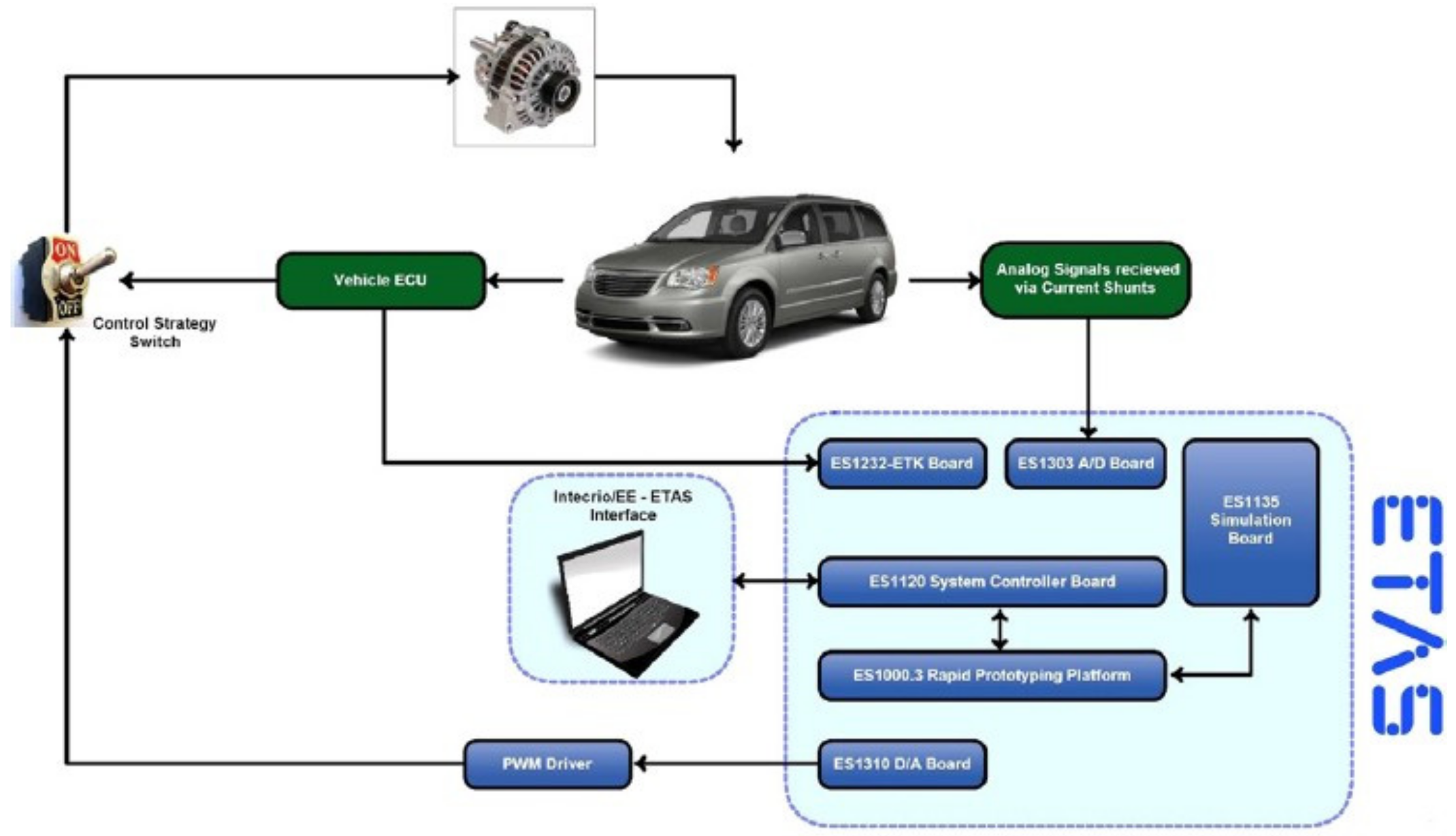
Figure 1. Block diagram for the experimental test rig [13].
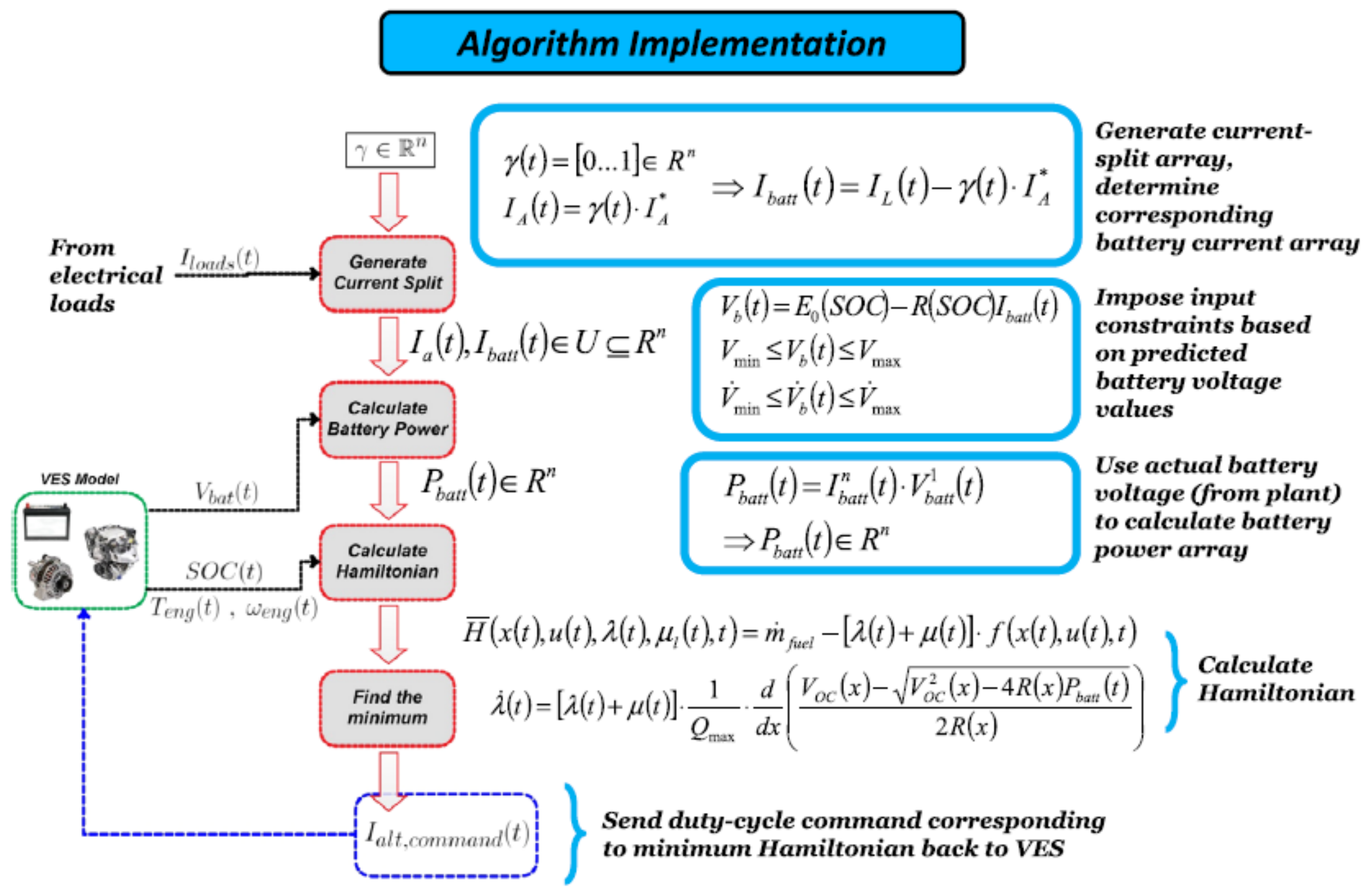
Figure 2. Block diagram of PMP control algorithm [13].
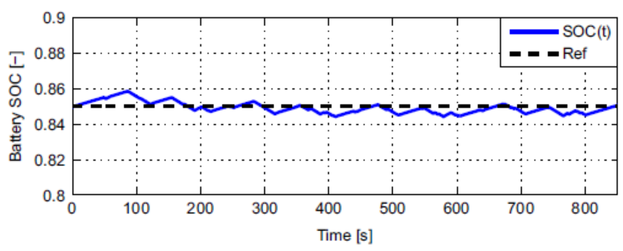
Figure 3. Result for state of charge of the battery using the proposed algorithm [13].
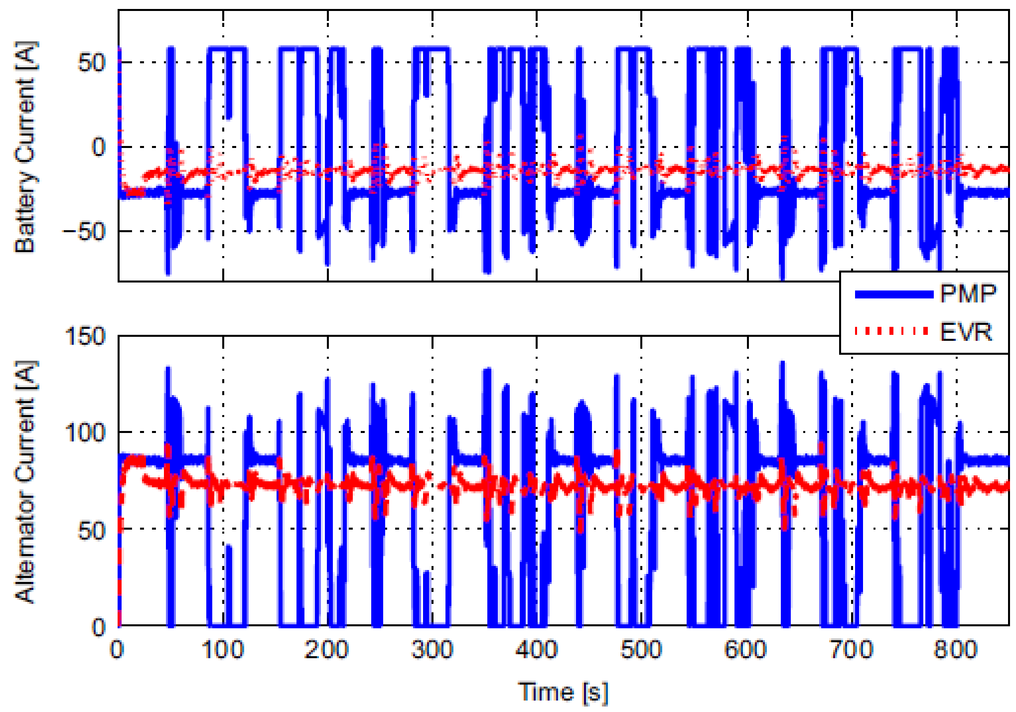
Figure 4. Battery and alternator current for the PMP and EVR algorithms [13].
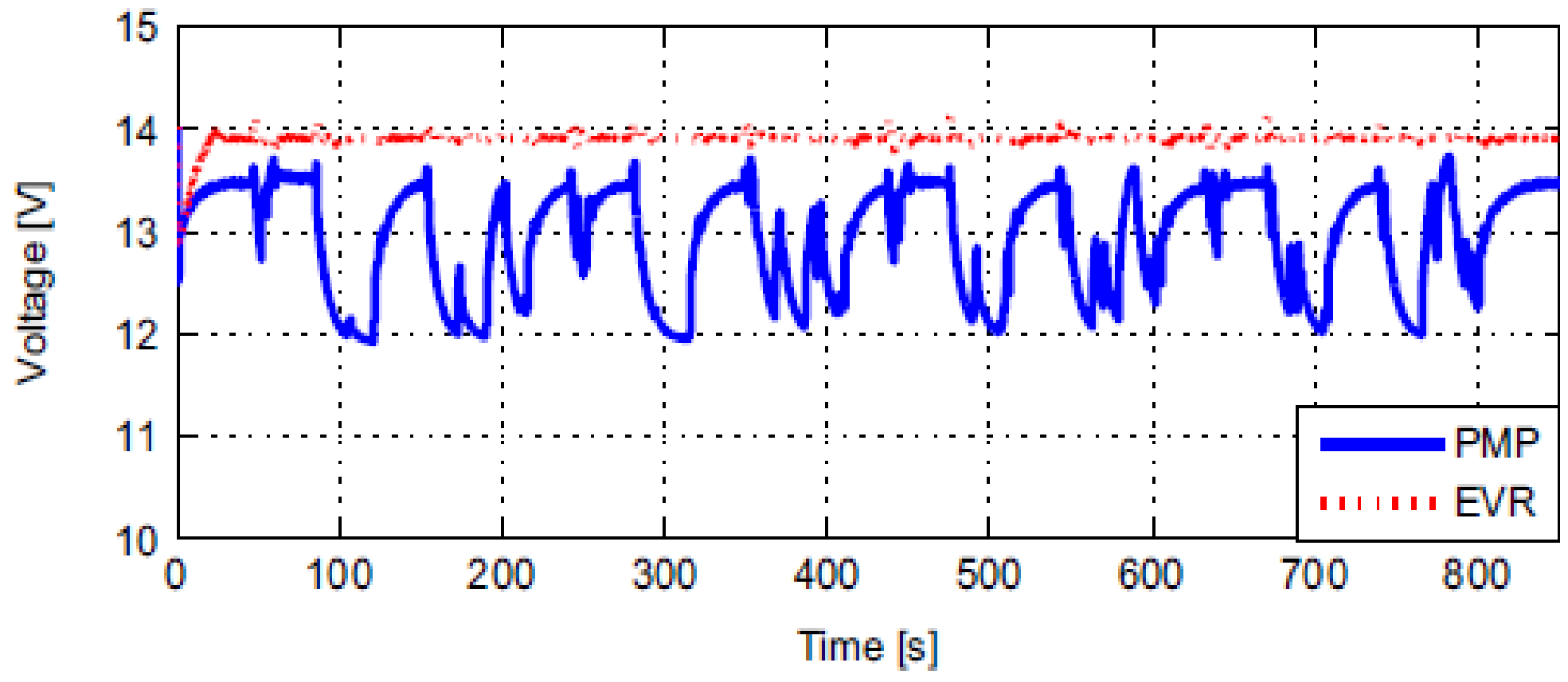
Figure 5. Battery and alternator current for the PMP and EVR algorithms [13].
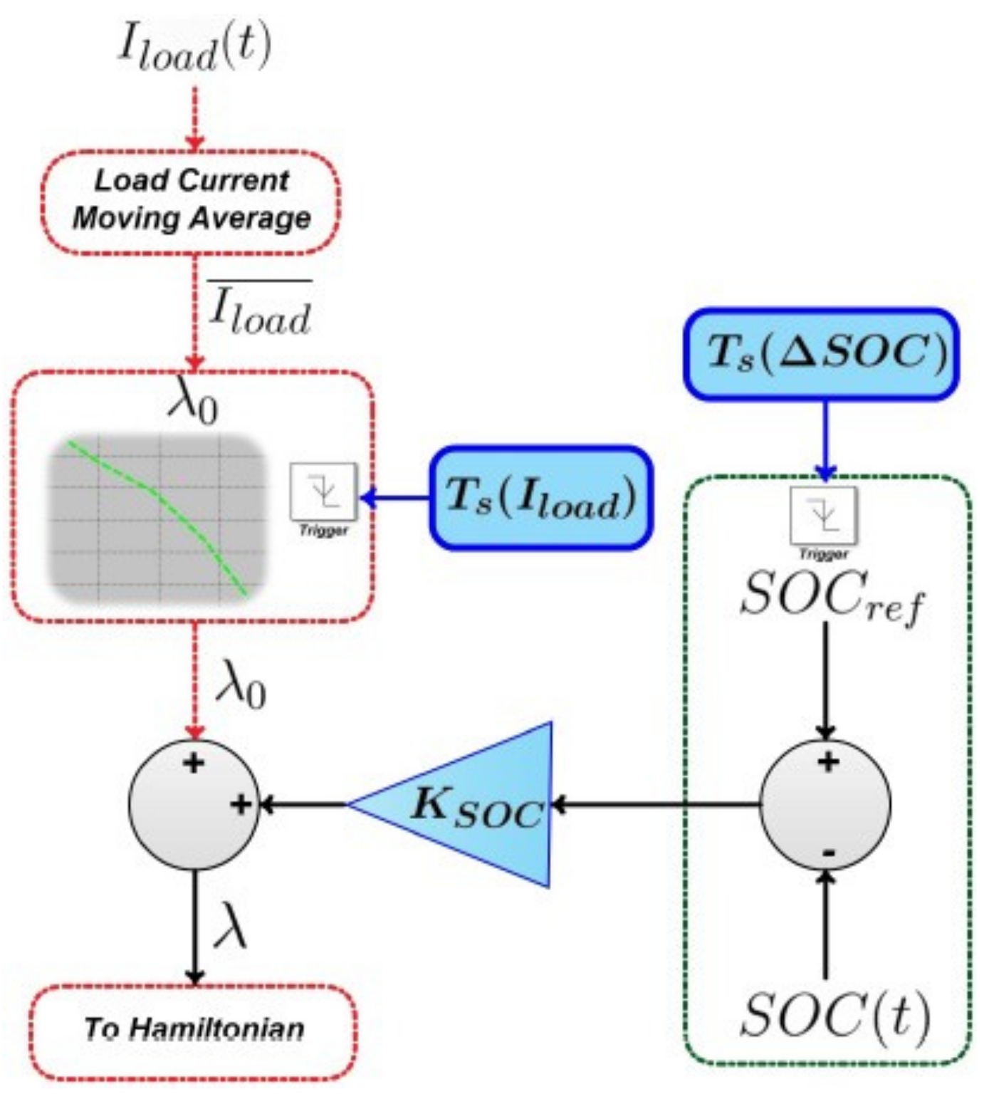
Figure 6. Flowchart for adaptive PMP algorithm [13].
2.2. Optimal Power Distribution (OPD)
Optimal power distribution OPD optimization is introduced to solve this problem in real-time performance. The proposed control method changed the intelligent alternator and the battery outputs during the load change and variation in driving conditions during real-time operation [14]. In a real-time manner, an intelligent battery sensor (IBS) collects the current and voltage information and evaluates the SOC for the battery. The intelligent alternator will conduct four modes of operation: the sleep or ready mode, the pre-excitation mode, voltage regulation mode, and finally, the off excitation mode. The alternator mode of operation is seen in Figure 7.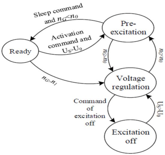
Figure 7. Modes of operation for the intelligent alternator [14].
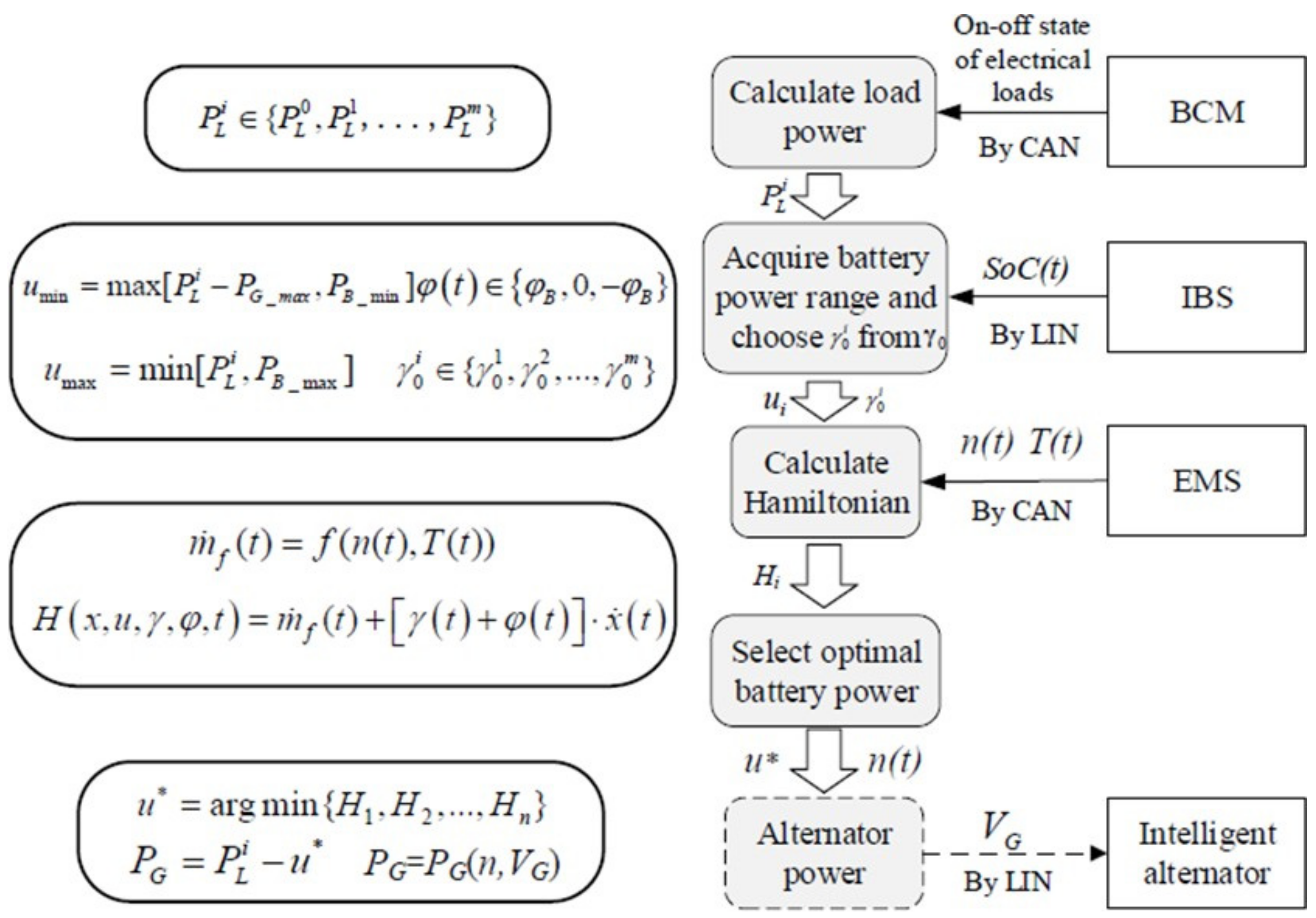
Figure 8. Flowchart for the OPD optimization algorithm [14].
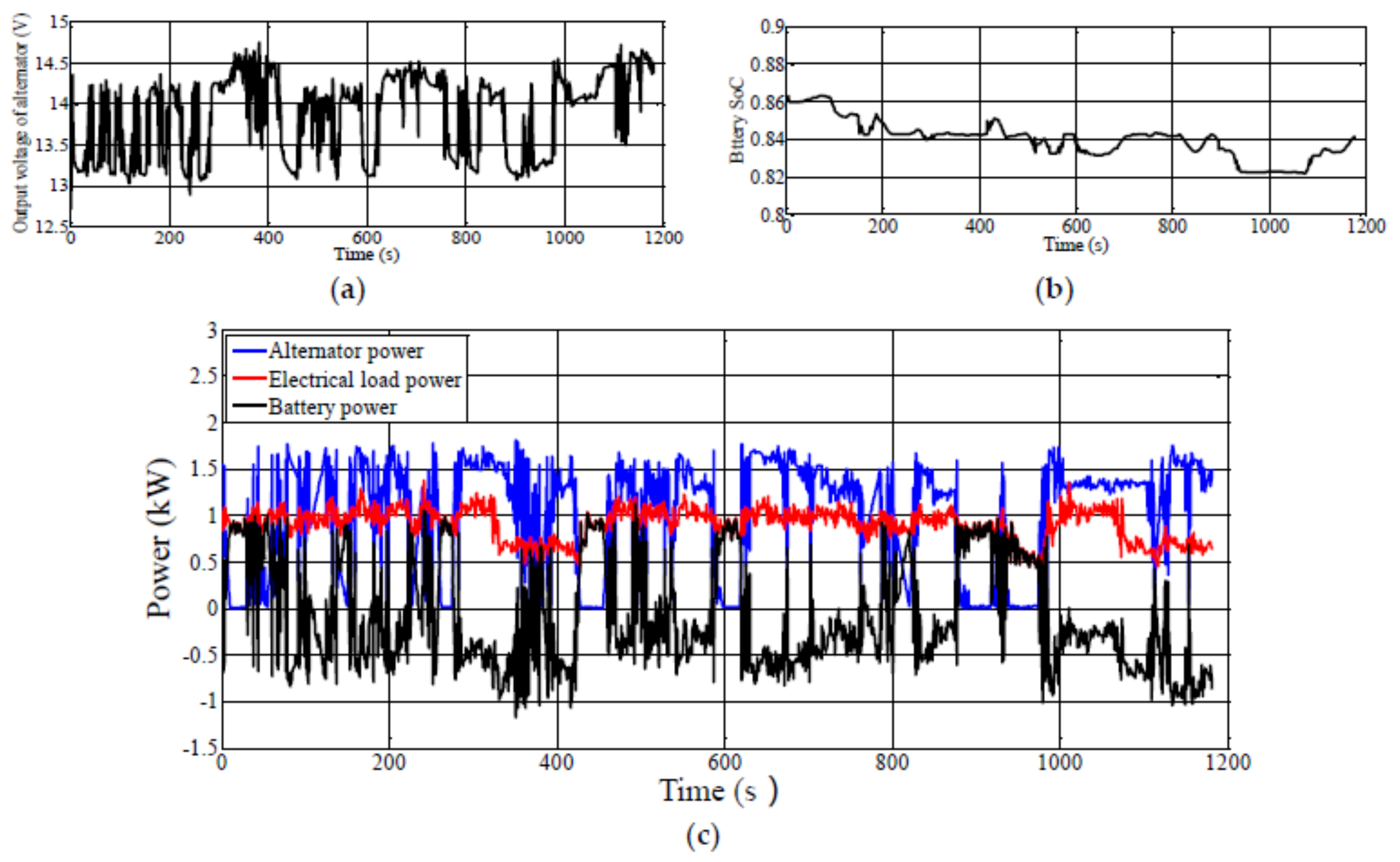
Figure 9. Experimental results for the proposed algorithm (a) alternator voltage, (b) battery SOC, and (c) alternator, load, and battery power [14].
2.3. Equivalent Consumption Minimization Strategy (ECMS)
Another supervisory energy management algorithm was proposed based on the “Equivalent Consumption Minimization Strategy” (ECMS) [15]. The optimization problem is to ensure economic fuel consumption for the vehicle by controlling the duty cycle of the alternator, and the constraints are the battery SOC, voltage, and load current. The baseline control algorithm is an essential voltage regulator that regulates the alternator duty cycle using a PID (Proportional, Derivative, and Integral) controller. The scheme of the alternator controller method is presented in Figure 10 below.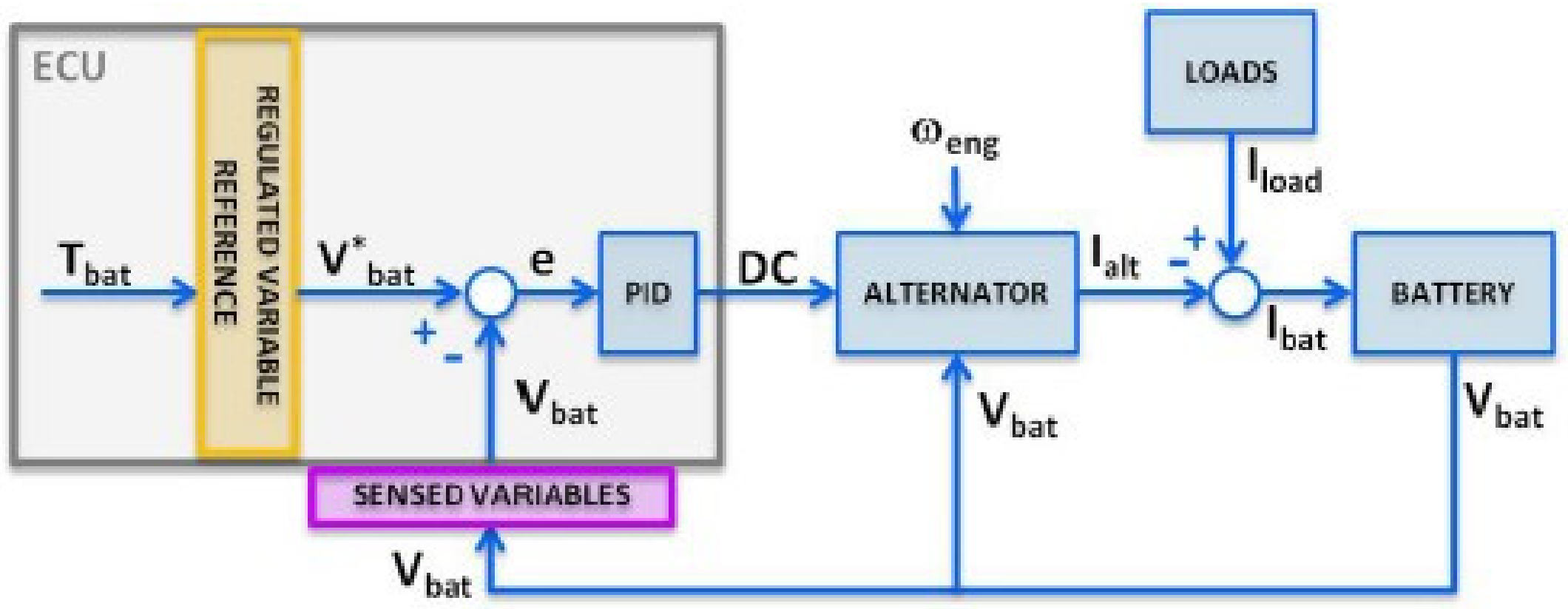
Figure 10. PID controller for alternator voltage regulator [15].
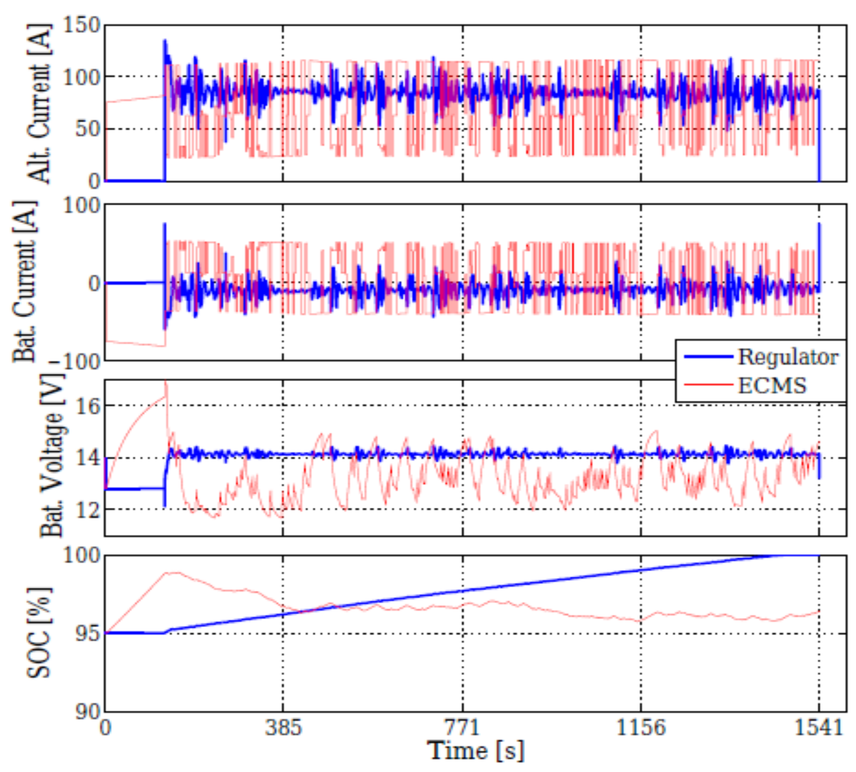
Figure 11. Simulation results for the proposed algorithm [15].
2.4. Model Predictive Controller (MPC) and Modified Dynamic Programming (DP)
In an alternator/battery combination, there is a freedom for the alternator to decide when the power will have generated, but this freedom is not used. The authors [16] used this freedom to design energy management controllers that reduce fuel consumption.
3. Optimization Using Power Electronic Techniques
In their thesis [17] and papers [18][19][20][21], the authors designed a control circuit for extracting maximum power from an Interior Permanent Magnet (PM) synchronous machine using SMR for automotive applications. In their work, the author justifies their selection for this type of alternator by using it as a current source that provides sufficient power to the load at a wide range of speeds (600–6000 rpm), and it is optimized for field weakening performance. In addition, this type of rectifier improved the output power by 66%. The essential idea is to extract the maximum power at the vehicle’s idle speed. PIC30F10 microcontroller was used to provide the gating signal to the unique switch for the SMR to adjust the output voltage according to the reference DC voltage, as is seen in Figure 12.
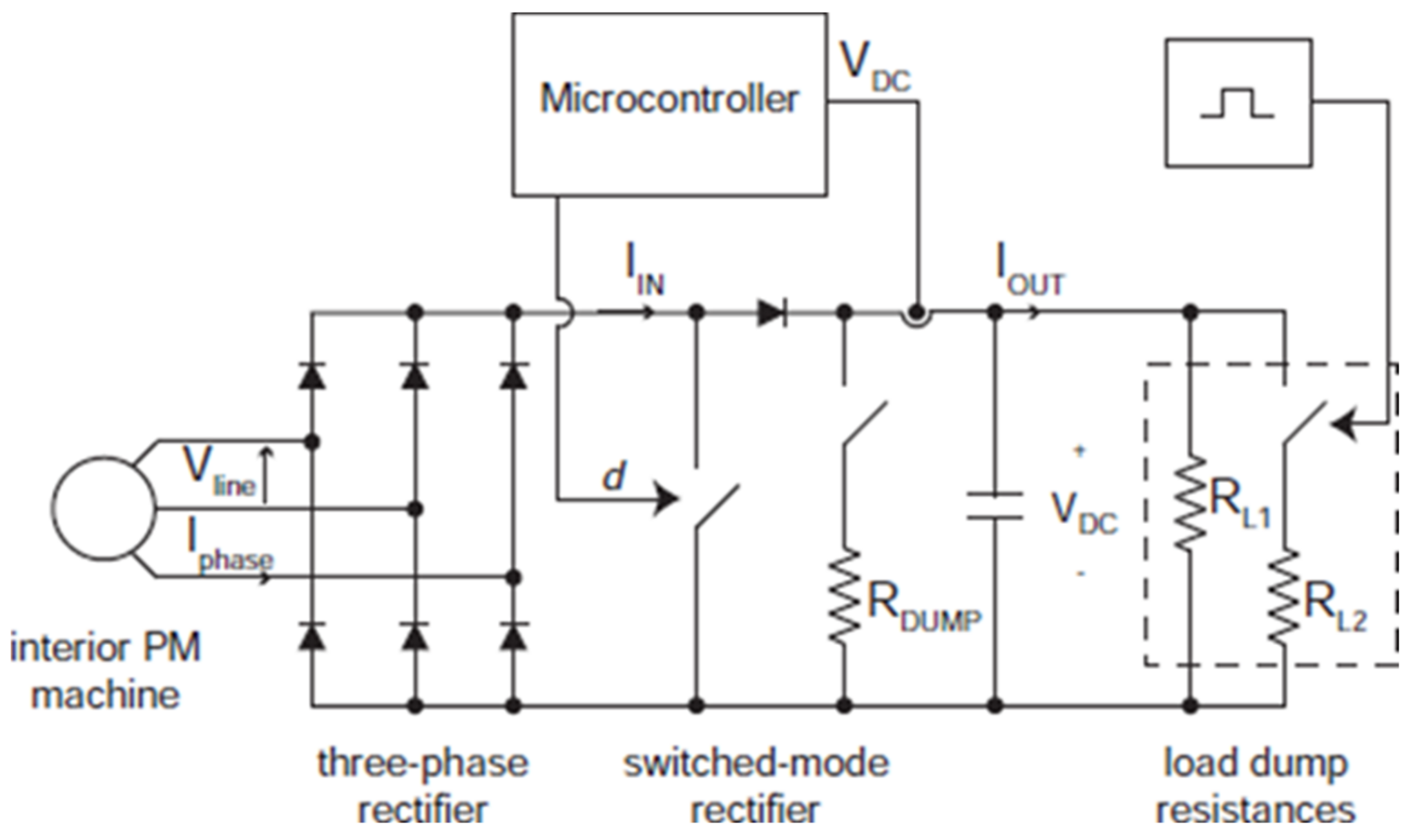
Figure 12. Closed-loop test for the PM alternator with switched-mode regulator (SMR) [17].
In addition, the authors in [22] designed auxiliary converters for multiple functions to control the alternator’s output. It consists of chargers, inverters, alternators, exciters, and converters of different voltage levels. Moreover, the authors [23] used an induction machine as a stator and alternator and a prototype belt-driven mechanism. An inverter and DC/DC converter were used to optimize the power obtained from the alternator. The authors [24] used a 42-V system to install additional subsystems efficiently. A three-phase 42-V 4-kW automotive power generating induction generator system is suggested. This system employs a low-cost diode rectifier directly linked to the inducing machine to transmit active power to batteries and the load. A new control algorithm is introduced in this work which regulates the output voltage by controlling the PWM inverter. The proposed system is as in Figure 13.
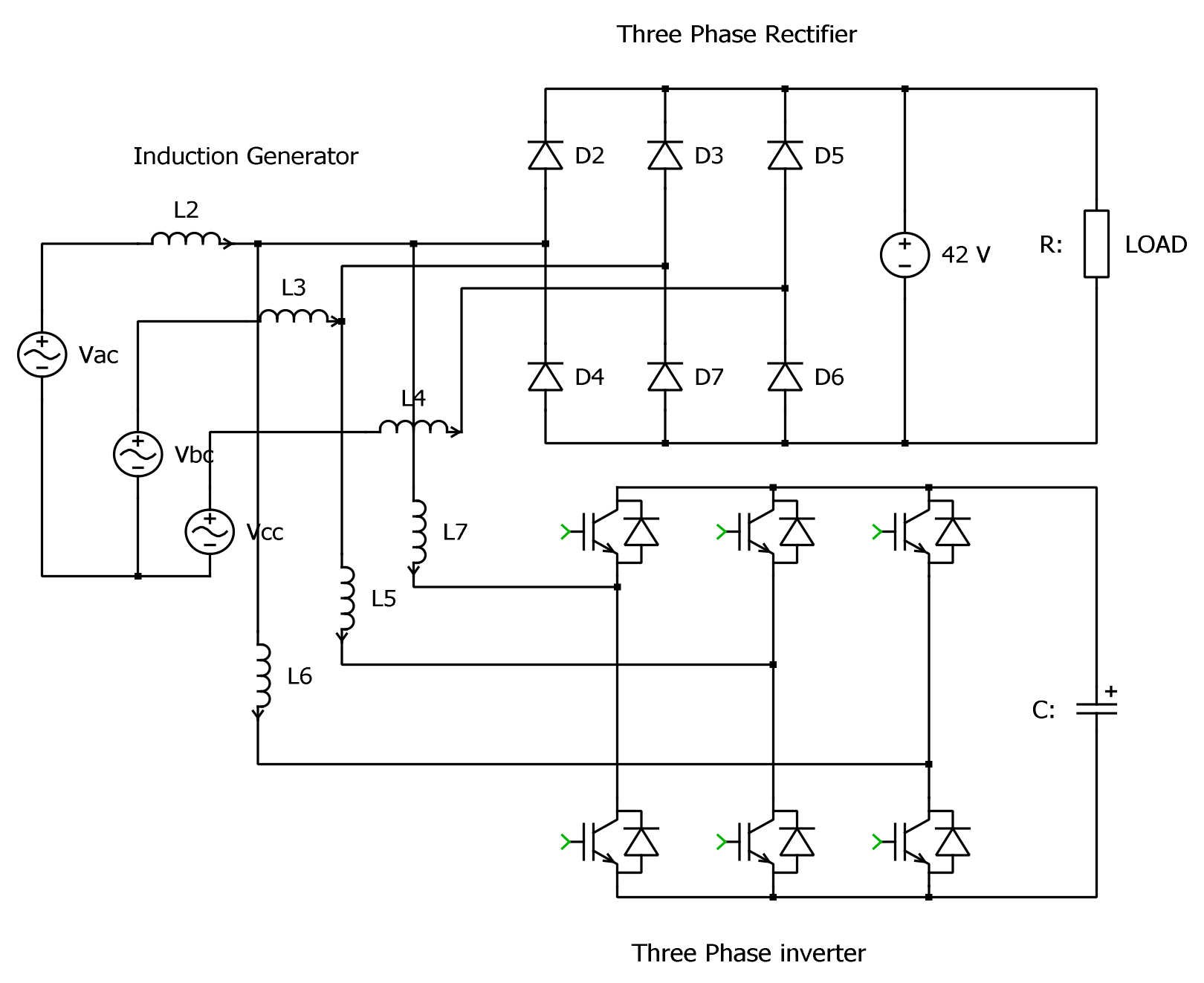
Figure 13. Induction generator with inverter and bridge rectifier [24].
In addition, the construction of a surface PM alternator was performed in the laboratory by the authors [25] using a single SCR (Silicon-Controlled Rectifier). The rectifier regulates the output voltage and power of the 3.4 kW vehicle alternator at high speed (up to 6500 rpm). The net efficiency of the alternator at high speed was 71% with full load applied.
Results indicate that at low output power (34 A 1445 W) and idle speed of 2150 rpm, the system efficiency was 84.5%, and the output voltage was kept at 42.5-volt. This high efficiency was due to the reduced losses for the rectifier.
Another surface PM starter-alternator combination was designed using Litz winding to minimize copper losses and improve system efficiency at higher speeds. An inverter controlled the output voltage, and the system’s total load efficiency was 96% at 3000 rpm [26]. The block diagram of the system is in Figure 14.
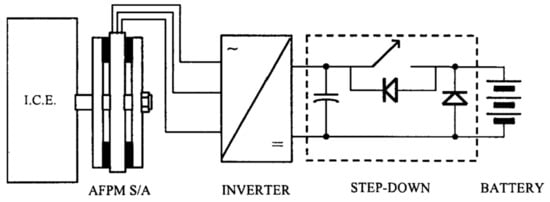
Figure 14. AFPM connection for the engine and inverter block diagram [26].
Similarly, the authors in [27] used the same axial flux permanent magnet alternator (AFPM) with a fully controlled AC to DC converter. Then, an intelligent controller was designed using an Arduino Uno board that uses an Atmel ATMega328P microcontroller. The controller is responsible for generating the gating signals for the converter using a comparator circuit. Firstly, the system was tested using Matlab Simulink, and then an experimental setup was introduced. The design of the controller depends on measuring the alternator output voltage, then a feedback signal from the battery side and PWM signals will be generated to change the switching sequence for the converter. High efficiency is obtained using the proposed system (94%) and good voltage regulation. A six-step inverter and controller were designed [28] to control the power output of the interior PM. The controllable inverter was synchronized with the alternator according to the output voltage’s zero-crossing data of the third harmonic. The load power is controlled by shifting the voltage to the third harmonic. The control device increases the alternator’s output by 43% with the same alternator as the traditional diode rectifier while the engine is idle and at high ambient temperature.
Because of its good performance and characteristics, the interior PM was also introduced as an alternator in [29]. An investigation of the application of a half-bridge SMR controller to an interior PM was achieved [30][31][32].
The rectifier performs maximum power extraction from the alternator using a new load matching technique. This arrangement allowed increasing the output power linearly from 1 kW at idle speed (1800 rpm) to about 4 kW (6000 rpm). Compared with the congenital diode rectifier, the SMR was increased almost three times (from 1.5 kW to 4 kW).
Losses for the electrical power system in the Lundell automotive alternators are studied in [33]. Tests for passive rectifiers used with the brushless interior permanent-magnet (PM) automotive Lundell alternator indicated that 10–12% of the losses are caused by the diode used in the converters. To overcome the complexity and high cost of the inverter, the authors in [34] designed an inverter less for brushless interior permanent magnet automotive alternator using a switched-mode converter. Many advantages have been found when using this type of alternator; firstly, it has high back electromotive voltage with high reluctance. In addition, it performs as a stable current source and has a wide range of operating speeds. A novel generic optimization method is implemented in [35] to calculate the reference signals used to optimize the Lundell alternator efficiency by minimizing the copper losses. This is achieved using an active metal-oxide-semiconductor field-effect transistor (MOSFET) rectifier at the alternator’s output using Matlab Simulink, and then an experimental setup is designed to verify the results. Results indicate high efficiency compared with a system that used a passive rectifier.
Power electronic is used again in [36] to produce a dual output voltage for the automotive alternator. The authors used SMRs to produce 42-volt and 14-volt outputs from the alternator. A full match for the load is achieved, and the delivered power for the two outputs is performed to any one of the combinations according to the load demand. Results indicated a good response and performance for the proposed combination.
Novel direct frequency tracking for synchronous rectifier (D-FTSR) is applied in [37]; this method is a practical dependent approach to control the output voltage of the synchronous rectifier connected to the automotive alternator. The D-FT approach is proposed in the article to solve the issue posed by continually and statistically fluctuating switching frequency. The D-FT approach might ensure that the switching tube operates in adaptive safe conduction time (SCT) concerning the rotor speed, preventing circuit oscillation and spurious ringing. The suggested driving circuit delivers accurate gate driving signals without the need for any extra passive circuits or sensors for rotor speed detection. The switching tube may operate like a typical diode with this driver, increasing the SR’s suitability for multiphase systems in automobile alternators.
Finally, a summary of the advantage and disadvantages of the power electronic devices used to enhance and optimize the alternator performance is in Table 23 below.
Table 23. Summary of Power Electronic Devices Effects on the Alternator Performance.
| Researchers | Algorithm | Enhancement | Disadvantages |
|---|---|---|---|
| C.-Z. Liaw, 2013, [17] | SMR | Improved the output power by 66%, high efficiency is obtained at low speeds, and finally, acceptable voltage fluctuation is measured. The type of the alternator is interior PM. This work is experimental. | No investigation has been made for the alternator performance at higher speeds. The accuracy of the proposed system is affected by the rectifier’s presence. |
| Henry et al., 2001, [23] | Inverter and DC/DC converter | The net efficiency was in the range of (73–79%). | The complex controller provides an output power of about 4 kW, but at high speed, this power was reduced to half at 4000 rpm, for example. |
| Naidu and Walters, 2003, [24] | Diode rectifier and voltage source PWM inverter | High efficacy at low speeds, but an excellent transient response for the controller was optioned. An induction generator is used as the power source in this work | It has lower efficiency at full speed, needing a complex controller. Not applied in the real world, and the work is a simulation only. |
| Naidu, Henry, and Boules, 2000, [25] | SCR rectifier | The obtained power was high at full speed, and the efficiency was 71%. A real-world Delphi R&D PM alternator is used in this work. | It used a complex controller. |
| El-Hasan, 2018, [26] | Full controlled AC to DC convertor | High efficiency is optioned (94%) and good voltage regulation. Axial-flux PM(AFPM) S/A alternator is used in a real LGA 340 OHC Lombardini engine. | The system suffered from temperature rise when the load was 49 A. |
| Liang, Miller, and Zarei, 1996, [28] | Six-step inverter | Output increased by 43%, and a good response was obtained. The salient pole Lundell alternator is the alternator type used in this work. | The system suffers from a high fluctuating of the output voltage. Experimental work is present but not used in the real world. |
| Perreault and Caliskan, 2004, [30] | Half-bridge SMR | They increase the output power linearly from 1 kW at idle speed (1800 rpm) to about 4 kW (6000 rpm). Lundell alternator is used in this work. | The system has low energy and efficiency at low speeds. |
| Hassan, Perreault, and Keim, 2005, [36] | Dual output SMR | Results indicated a good response and performance for the proposed combination. Slandered Lundell alternator (14-V 65/130 A) is used in this work. It is used as an experimental setup to verify the proposed system. | Complex circuit, and it needs an axillary control device. It works only on the alternator’s output, not on the regulating of the field current. |
| J. Wan, 2022, [37] | D-FTSR | A novel approach to tracking the engine speed to control the alternator output frequency enhanced alternator efficiency by 8% and can be applicable in a wide range of alternators. The work is verified using an experimental setup. | It controls only the rectifier output and does not deal with the field voltage control. The type of the alternator is not specified in this work. |
4. Conclusions
Many optimization techniques and approaches for the automotive alternator are presented in this work. Each approach’s principle and effect are explained, discussed, and analyzed. The optimization methods presented in this work can be divided into many techniques; that is, approaches deal with optimizing the output power of the alternator and using the power electronic devices with some suitable controllers to force the alternator to produce the maximum power. Some optimization techniques deal with the alternator’s execution current only; others control the alternator’s output voltage. The most suitable and robust approach simultaneously maintains the excitation current and the alternator’s output voltage. Although the last technique requires complex control and optimization tools, it enhances the alternator’s efficiency and reduces the fuel consumption of the ICE. Some of these methods cannot be applied in a real-time manner, but the methods that are applicable in real-time give the most accurate results, and hence it gives a self-optimization to the alternator during its operating cycle. The powerful and most suitable technique is using Multi-Variable Sliding-mode Extremum Seeking because it enhances the alternator’s efficiency and performs in a real-time manner with high accuracy.
References
- Mazlan, R.K.; Dan, R.M.; Zakaria, M.Z.; Hamid, A.H.A. Experimental study on the effect of alternator speed to the car charging system. MATEC Web Conf. 2016, 90, 1076.
- Ali, H.; Sulaiman, E.; Aziz, R.; Jenal, M.; Ahmad, M.Z.; Khan, F. Review of Double Stator Flux switching machines with various arrangements of excitation sources. Alex. Eng. J. 2021, 60, 4393–4410.
- Chiara, F.; Canova, M. A review of energy consumption, management, and recovery in automotive systems, with considerations of future trends. Proc. Inst. Mech. Eng. Part D J. Automob. Eng. 2013, 227, 914–936.
- Gecha, V.Y.; Goncharov, V.I.; Chirkin, V.G.; Shirinskii, S.V.; Petrichenko, D.A. Linear Alternator with Reciprocating Mover: Review of Designs and Machine Types. Biosci. Biotechnol. Res. Asia 2015, 12, 409–418.
- Kamalakannan, C.; Kamaraj, V.; Paramasivam, S.; Paranjothi, S.R. Switched Reluctance Machine in Automotive Applications A Technology Status Review. In Proceedings of the 1st International Conference on Electrical Energy Systems, Chennai, India, 3–5 January 2011; pp. 187–197.
- Li, S.; Zhang, S.; Habetler, T.G.; Harley, R.G. Modeling, Design Optimization, and Applications of Switched Reluctance Machines—A Review. IEEE Trans. Ind. Appl. 2019, 55, 2660–2681.
- Rahman, S.A.; Masjuki, H.; Kalam, M.; Abedin, M.; Sanjid, A.; Sajjad, H. Impact of idling on fuel consumption and exhaust emissions and available idle-reduction technologies for diesel vehicles—A review. Energy Convers. Manag. 2013, 74, 171–182.
- Reddy, K.J.; Natarajan, S. Energy sources and multi-input DC-DC converters used in hybrid electric vehicle applications—A review. Int. J. Hydrogen Energy 2018, 43, 17387–17408.
- Boldea, I. Automobile Electrification Trends: A Review. In Proceedings of the 2007 International Aegean Conference on Electrical Machines and Power Electronics, Bodrum, Turkey, 10–12 September 2007; pp. 369–377.
- Saponara, S.; Lee, C.H.; Wang, N.X.; Kirtley, J.L. Electric Drives and Power Chargers: Recent Solutions to Improve Performance and Energy Efficiency for Hybrid and Fully Electric Vehicles. IEEE Veh. Technol. Mag. 2020, 15, 73–83.
- Gathadi, P.; Bhole, A. Electric Motors and Rotor Position Detection Techniques of Integrated Starter Alternator for HEV: A Review. In Proceedings of the 2018 International Conference on Current Trends towards Converging Technologies (ICCTCT), Coimbatore, India, 1–3 March 2018; pp. 1–6.
- Enang, W.; Bannister, C. Modelling and control of hybrid electric vehicles (A comprehensive review). Renew. Sustain. Energy Rev. 2017, 74, 1210–1239.
- Waldman, C.; Gurusubramanian, S.; Fiorentini, L.; Canova, M. A model-based supervisory energy management strategy for a 12 V vehicle electrical system. Control Eng. Pr. 2015, 44, 20–30.
- Wang, Y.; Hu, H.; Zhang, L.; Zhang, N.; Sun, X. Real-Time Vehicle Energy Management System Based on Optimized Distribution of Electrical Load Power. Appl. Sci. 2016, 6, 285.
- Couch, J.; Fiorentini, L.; Canova, M. An ECMS-Based Approach for the Energy Management of a Vehicle Electrical System. IFAC Proc. Vol. 2013, 46, 115–120.
- Koot, M.; Kessels, J.T.; de Jager, B.; Heemels, W.P.M.H.; van den Bosch, P.P.J.; Steinbuch, M. Energy management strategies for vehicular electric power systems. IEEE Trans. Veh. Technol. 2005, 54, 771–782.
- Liaw, C.Z. A High Power Interior Permanent Magnet Alternator for Automotive Applications. 2013. Available online: https://digital.library.adelaide.edu.au/dspace/bitstream/2440/83587/8/02whole.pdf (accessed on 23 February 2022).
- Liaw, C.-Z.; Whaley, D.; Soong, W.; Ertugrul, N. Investigation of inverterless control of interior permanent-magnet alternators. IEEE Trans. Ind. Appl. 2006, 42, 536–544.
- Liaw, C.; Soong, W.; Ertugrul, N. Closed-Loop Control and Performance of an Inverterless Interior PM Automotive Alternator. In Proceedings of the International Conference on Power Electronics and Drives Systems, Kuala Lumpur, Malaysia, 28 November–1 December 2005; Voulme 1, pp. 343–348.
- Liaw, C.-Z.; Soong, W.L.; Welchko, B.A.; Ertugrul, N. Uncontrolled Generation in Interior Permanent-Magnet Machines. IEEE Trans. Ind. Appl. 2005, 41, 945–954.
- Liaw, C.; Soong, W.; Ertugrul, N. Low-Speed Output Power Improvement of an Interior PM Automotive Alternator. In Proceedings of the Conference Record of the 2006 IEEE Industry Applications Conference Forty-First IAS Annual Meeting, Tampa, FL, USA, 8–12 October 2006; Volume 1, pp. 27–34.
- Ilončiak, J.; Struharnanský, Ľ.; Kuchta, J. Modular Concept of Auxiliary Converters for Diesel Electric Locomotives. Procedia Eng. 2017, 192, 359–364.
- Henry, R.R.; Lequesne, B.; Chen, S.; Ronning, J.J.; Xue, Y. Belt-Driven Starter-Generator for Future 42-Volt Systems; (No. 2001-01-0728); SAE Technical Paper; SAE International: Warrendale, PA, USA, 2001.
- Naidu, M.; Walters, J. A 4-kW 42-V induction-machine-based automotive power generation system with a diode bridge rectifier and a PWM inverter. IEEE Trans. Ind. Appl. 2003, 39, 1287–1293.
- Naidu, M.; Henry, R.; Boules, N. A 3.4 kW, 42 V High Efficiency Automotive Power Generation System; SAE International: Warrendale, PA, USA, 2000.
- Caricchi, F.; Crescimbini, F.; Santini, E.; Solero, L. High-efficiency low-volume starter/alternator for automotive applications. In Proceedings of the Conference Record of the 2000 IEEE Industry Applications Conference. Thirty-Fifth IAS Annual Meeting and World Conference on Industrial Applications of Electrical Energy (Cat. No. 00CH37129), Rome, Italy, 8–12 October 2000; Volume 1.
- El-Hasan, T.S. Development of Automotive Permanent Magnet Alternator with Fully Controlled AC/DC Converter. Energies 2018, 11, 274.
- Liang, F.; Miller, J.; Zarei, S. A control scheme to maximize output power of a synchronous alternator in a vehicle electrical power generation system. In Proceedings of the IAS ‘96. Conference Record of the 1996 IEEE Industry Applications Conference Thirty-First IAS Annual Meeting, San Diego, CA, USA, 6–10 October 1996.
- Lovelace, E.; Jahns, T.; Lang, J.H. Impact of saturation and inverter cost on interior PM synchronous machine drive optimization. IEEE Trans. Ind. Appl. 2000, 36, 723–729.
- Perreault, D.; Caliskan, V. Automotive Power Generation and Control. IEEE Trans. Power Electron. 2004, 19, 618–630.
- Rivas, J.M.; Perreault, D.J.; Keim, T.A. Performance Improvement of Alternators with Switched-Mode Rectifiers. IEEE Trans. Energy Convers. 2004, 19, 561–568.
- Rivas, J. Output Power Increase at Idle Speed in Alternators. Ph.D. Thesis, Massachusetts Institute of Technology, Cambridge, MA, USA, 2003.
- Sarafianos, D.; Logan, T.G.; McMahon, R.A.; Flack, T.J.; Pickering, S. Alternator Loss Breakdown and Use of Alternative Rectifier Diodes for Improvement of Vehicle Electrical Power System Efficiency. In Proceedings of the 16th International Power Electronics and Motion Control Conference and Exposition, Antalya, Turkey, 21–24 September 2014; pp. 502–507.
- Soong, W.; Ertugrul, N. Inverterless High-Power Interior Permanent-Magnet Automotive Alternator. IEEE Trans. Ind. Appl. 2004, 40, 1083–1091.
- Sarafianos, D.; Llano, D.X.; Ghosh, S.S.; McMahon, R.A.; Pickering, S.; Flack, T.J. Control Strategy for a Multiphase Lundell-Alternator/Active-Rectifier System in 14 V Automotive Power Systems. IEEE Trans. Transp. Electrif. 2019, 5, 347–355.
- Hassan, G.; Perreault, D.; Keim, T. Design of Dual-Output Alternators with Switched-Mode Rectification. IEEE Trans. Power Electron. 2005, 20, 164–172.
- Wan, J.; Zeng, X.; Li, Z.; Li, L.; Yang, Y.; Zhao, Y.; Li, Z.; Zhang, B. A Novel Synchronous Rectification with Directly Frequency Tracking for Automotive Alternator. IEEE Trans. Ind. Electron. 2021, 69, 2216–2226.
More