Your browser does not fully support modern features. Please upgrade for a smoother experience.
Please note this is a comparison between Version 2 by Jason Zhu and Version 3 by Jason Zhu.
Smart maintenance is essential to achieving a safe and reliable railway, but traditional maintenance deployment is costly and heavily human-involved. Ineffective job execution or failure in preventive maintenance can lead to railway service disruption and unsafe operations. The deployment of robotic and autonomous systems was proposed to conduct these maintenance tasks with higher accuracy and reliability. In order for these systems to be capable of detecting rail flaws along millions of mileages they must register their location with higher accuracy. A prerequisite of an autonomous vehicle is its possessing a high degree of accuracy in terms of its positional awareness.
- localisation
- sensor fusion
- railway maintenance
- autonomous systems
1. Introduction
Rail transportation demand is steadily increasing over the world, particularly in metropolitan regions with rapidly growing populations. Even in Europe, where population growth is slower, estimates show an increase in the proportion of people who travel by train. This causes national railways infrastructure maintenance and renewals costs across a total of around 300,000 km of combined track and exceeding €25 billion per annum across Europe [1][2]. Harnessing data and analytics could help European rail infrastructure operators to better target their maintenance spending more productively. In Great Britain’s rail network, there are 40,000 bridges and tunnels, 9000 level crossings, and 9941 miles (16,000 km) of railway tracks. It has been reported [3][4] that in Great Britain the rail network experiences 4.7 million train journeys every single day, demonstrating the importance of railway infrastructure. Railways require regular maintenance to ensure safe operating conditions. It costs over £1 billion per annum in the UK, accounting for 18% of Network Rail’s overall expenditure [5][6]. The high-level quantitative information relating to maintenance is depicted in Figure 1, which shows the trends in total maintenance in terms of 2020–2021 prices. Maintenance expenditure has been steadily increasing since 2013–2014 and is expected to reach over 1830 million pounds in 2020–2021.
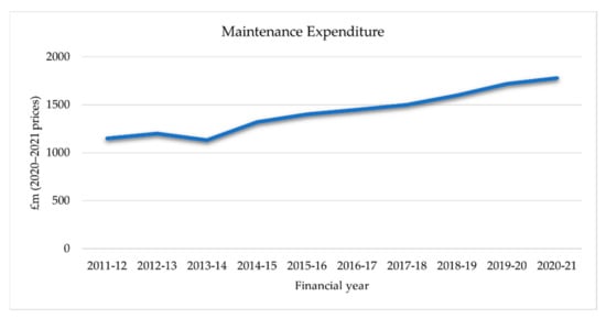
Figure 1. Total maintenance expenditure, 2011–2012 to 2020–2021 (2020–2021 prices).
Therefore, preserving or improving the safety, reliability, and quality of the whole railway system is a key challenge, and is paramount for passengers, employees, and the entire rail network. Without reliable rail track maintenance, the safety of the rail network will be at risk, and delays would occur regularly. For these reasons, innovative maintenance solutions for railway systems, as well as the integration of maintenance into operations, are constantly studied and developed to ensure a better management of the railway network.
Today, different industry sectors benefit from automation, which has led to the development of a number of robotic solutions to maintain and repair applications in the industry. For instance, miniature robot models have been applied in different maintenance tasks, including in highways, aircraft servicing, underwater facilities, power line maintenance [7], fault detection [8], and track cleaning or performing repair jobs such as 3D printing [9][10]. A wheeled robot with a manipulator can undertake a variety of dangerous and remote operational tasks such as tunnel inspection [11] or the cleaning of nuclear reactors [12]. They could also be utilised in the inspection and maintenance of railway tracks [13]. Automation and computational intelligence techniques can dramatically improve the efficiency and effectiveness of maintenance. This guideline additionally applies to the railway maintenance industry [14].
Many different robots have been designed to do various railway track maintenance tasks; however, most of them are limited to specific scenarios, uses, or applications [15]. To perform the intended tasks, autonomous robots, as with all other technical systems, must meet certain requirements that vary depending on the individual application or task.
Autonomous systems will be one element involved in solving the trade-off between the transport capacity challenge and the maintenance cost and time reduction. Rail infrastructure managers from all over the world are interested in developing automatic inspection systems that can detect rail flaws, sleepers’ irregularities, and missing fastening elements as high-speed railway traffic grows. These systems can improve the ability to detect defects and minimise inspection time, allowing for more frequent railway network maintenance. The condition of the railway track is also monitored as part of the maintenance strategy [16]. Currently, industries use equipment for inspection and maintenance activities separately; these two activities have not yet been merged. The introduction of artificial intelligence (AI) and cognitive analytics technologies into these two procedures can make the entire process dynamic and autonomous [15].
2. Railway Maintenance Objectives and the Related Techniques
2.1. Maintenance Policy
Rail track maintenance encompasses all technical and administrative actions aimed at inspecting, repairing, and maintaining railway tracks in order to keep trains moving smoothly and securely while also extending their service life [17][18]. The following are the primary objectives of railway track maintenance:
-
Due to the high speed of trains, heavy axle loads, and repetitive loads, the track structure’s strength continues to deteriorate.
-
The track structure is subjected to various degrading factors such as rain, sunlight, and wind. The deterioration of rolling stock and rails is unavoidable.
-
The track structure has to withstand so many other curvatures, speeds, and load effects, particularly at curves, points, and crossings.
For these reasons, it is critical to maintain railway track on a regular basis. Railway maintenance tasks, however, are costly, and poor maintenance or an inability to conduct preventive maintenance will result in severe consequences. As a result, the application of robotic and autonomous systems in this area is proposed to undertake these maintenance tasks with higher accuracy and reliability. According to the conducted research in [19], the majority of robotic and autonomous systems advances in railway inspection and maintenance areas are related to the rolling stock and rail track, with 56% and 28%, respectively. The cost-effectiveness of robotics automation in railway track maintenance and related tasks have been already proven [20].
Today, track maintenance—including replacement, track stabilization, ballast injection (stone blowing), sleeper replacement, tamping the ballast, excavation, spiking rail, tightening bolts, and aligning the track—is achieved through the utilisation of highly specialised machines [21]. A number of these robots are massive and can conduct more than one task, for instance, ballast tamping combined with track lining and leveling. However, in order to get the best result for each part, it is decided that a specific robotic system should be applied for each task. As a result, each individual robot will concentrate on a single target for doing a highly specialised and efficient job.
In terms of railway track maintenance, a fully autonomous robotic system detects and removes sleeper bolts, feeds new fastener, and assembles them in high-speed train lines [22]. Rowshandel et al. [23][24] suggested an integrated robotic system comprising of a mechanised trolley, a robot, a commercially available alternating current field measurement (ACFM) device, and a laser distance sensor for the highlight precise identification and characterisation of surface-breaking defects in rails. Auto-Scan [25] is another example of an autonomous rail inspection system. It is an autonomous trolley that detects defects on the railway track using electromagnetic acoustic transducers (EMATs). RailPod [26], a commercially available autonomous rail inspection robotic platform, can run both on and off track, but only on plain surfaces, because it has both rail and pneumatic wheel reconfigurable mechanisms.
A robust rail condition monitoring methodology was proposed in [27], in which a laser scanner mounted on a moving rail vehicle to detect track fractures, scorings, and excessive wear was applied. An autonomous track geometry diagnostician’s computer system which flags poor track locations was proposed in [28]. Missing or broken track components including bolts, clips, ties, tie plates, anchors, and turnout components have also been detected using robotic and autonomous systems [29]. For instance, a new method for detecting missing or defective rail fastener problems has been proposed in previous research [30] which uses the histogram of oriented gradients information and a mixture of linear Support Vector Machine (LSVM) classifiers.
Besides providing infrastructures with an autonomous maintenance vehicle, proper maintenance of railway assets is also necessary and should be done periodically. This can be periodic updating, periodic comprehensive maintenance, regular inspection, and key repairing of track [31]. Services are at significant risk of failure if they are not properly maintained, with negative consequences for user satisfaction and asset professionals’ performance. As a result, two types of maintenance techniques have been established by National Rail to keep the tracks as functional as possible: preventive and corrective railway maintenance. Both demand a significant amount of resources, specialised equipment, and well-trained personnel [32].
2.1.1. Preventive Maintenance
Preventive maintenance (PM) is an important part of maintenance activity. An integral aspect of PM is systematic inspection, detection, and repair of incipient failures, either before their occurrence or before they proceed to a failure state, by competent persons involved in maintenance [33][34]. The main goals of PM are to extend the useful life of capital equipment, reduce critical equipment breakdowns, improve the planning and scheduling of needed maintenance works, reduce production losses due to equipment failures, promote the health and safety of maintenance personnel, and provide maximum system reliability and safety with the least amount of maintenance resources [35]. PM is divided into the following options, as shown in Figure 2:
-
Inspection: comparing physical, electrical, mechanical, and other properties (as appropriate) to the expected standards to evaluate the serviceability of materials/items.
-
Servicing: cleaning, lubricating, charging, preserving, and so on, of items/materials on a regular basis to avoid incipient breakdowns.
-
Calibration: determining the value of an item’s attributes on a regular basis by comparing it to a recognised standard with known accuracy.
-
Testing: testing or checking out on a regular basis to verify serviceability and discover electrical/mechanical degradation.
-
Alignment: changing the stated variable aspects of an item in order to achieve optimum performance.
-
Adjustment: periodically modifying specified material variable parts in order to achieve optimal system performance.
-
Installation: regular replacement of limited-life parts or equipment experiencing time cycle or wear degradation to maintain the stated system tolerance.
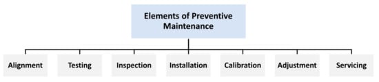
Figure 2. Elements of preventive maintenance.
Preventive maintenance for these operations takes place at specified intervals or according to certain criteria to limit the likelihood of equipment failure or degradation in their functioning. Because of the structure of a rail track, each element must be considered, as mispositioning of one of them might result in poor alignment and, in the worst-case scenario, train derailment. As a result, it can be divided into two parts: day-to-day maintenance (scheduled continuously) and seasonal maintenance [36].
-
Day-to-day maintenance:
The goal of this type of maintenance, from first inspection to final control, is to get the track operational and running as soon as possible. Three main units are mostly used for maintaining the track: stoneblowers, tampers, and Dynamic Track Stabilisation (DTS) machines [37]. These machines are employed for large-scale refurbishment projects, while a vast fleet of other units operates for smaller tasks. Stoneblowers and tamping machines act on the ballast and the rail. These three devices allow the track to be repositioned and reinforced. The purpose of the operations is to fix the track’s position by shifting the ballast and adjusting rails and sleepers. However, maintenance also entails the removal of defects, particularly from the rail. As previously stated, the rail is prone to many failures as a result of the train’s passing and the force exerted, and if not addressed promptly, the defect might spread and lead to the disintegration of the rail [38]. The most common rail problems are head check, gauge corners, cracks, and squats, which begin on the rail surface but spread deeper if trains continue to run [38]. This can be kept in check by routinely grinding the rail surface and lubricating the joint between the rail and the wheels.
-
Seasonal Track Maintenance:
Weather is another factor that that has a significant impact on the train’s operating conditions. Temperature changes, leaves, plants, and ice can either damage the track or limit the train’s abilities. The functional operation of the track, as well as the safety of passengers, are significantly influenced in this circumstance [39]. Various operations are carried out to address this problem depending on the weather conditions. In the winter, for instance, rails are prone to freezing and ice formation; in this situation, scraping or blowing hot air and then spraying hot liquid on the rail will prevent the rail from freezing [38]. In autumn, leaves on the rail reduce the friction between the wheels and the rail, causing friction to increase and the train’s wheels to hardly adhere to the rail, especially during acceleration phases. In this situation, the Rail Head Treatment Trains (RHTT) blowing high pressured air would remove the leaves. It then adds an adhesion gel to the wheels to strengthen their grip on the rail. Workers are also meant to cut down the trees that are suspected of colliding with the train. Plants on the railway track begin to grow in the summer, causing the track’s structure to become unsettled. In this case, herbicides are sprayed on the track to kill the seeds, and vegetation is pruned back to maintain the accessibility of the track. Another issue in the summer season is temperature. As rails are thermal conductors, they retain the heat. As a consequence, they expand and are no longer in their proper position [38], meaning that trains are subject to derailment. To prevent this failure, some parts of the rail are painted in white to reflect the sun’s rays. However, in other circumstances, preventing expansion is insufficient, and the rail tension is adjusted to allow the track to dilate and stretch without buckling.
2.1.2. Corrective Maintenance
Corrective maintenance (CM) is the task of locating, isolating, and resolving a fault so that failed equipment can be substituted or restored to an operational condition within the tolerances or limits set for in-service operations [33]. It plays a significant role in the efficiency of maintenance organisations. Sometimes, the track is too damaged to be restored or upkeep may be too costly [32]. In this case, corrective maintenance—which consists in replacing the degraded pieces [34]—is undertaken. Concerning railway maintenance, two types of operations are carried out depending on the damage level. If only a small portion of rail requires repair—for instance, replacement of a small part—manual operations are done, including cutting out the defective rail part, removing the rail part from the site using the road-rail vehicle, clearing the space around it, bringing the new rail, proceeding to illuminate thermic welding, proceeding to profile and grinding, and inspecting the final rail [32]. However, for more advanced maintenance, specifically designed machines conduct the tasks.
The CM process takes time to be achieved and requires the use of multiple machines as well as the participation of several personnel. The activities for larger maintenance are almost entirely automated. Track renewal is done when the rails have sustained too much damage. From the dismantling of the previous rails through to the inspection of the new track, a special purpose machine is employed to assure the complete replacement of the track [40]. In total, CM may be classified into five major categories: fail-repair, salvage, rebuild, overhaul, and servicing, as shown in Figure 3:
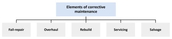
Figure 3. Elements of corrective maintenance.
3. Railway Vehicle Localisation Strategies
Railway vehicle positioning plays a prominent role in the safety of the system since the positioning information is used for train separation and control. Rail vehicles are confined to travel along the railway and an error in train location might result in a dangerous overestimation of braking distance. Therefore, an accurate and reliable estimation of the location of rail vehicles such as trains, trams, subways, and rail-robots is critical to rail-system management [41][42]. A wide range of sensors and infrastructures have been proposed and implemented for railway vehicle positioning, and so their classification is required. These sensors are mostly divided into two classes:
- (1)
-
Elements in the railway environment (infrastructure-based)
- (2)
-
On-board sensors (infrastructure-less)
3.1. Track Infrastructures-Based Strategy
Infrastructures in the railway environment are used as a way of determining the location of trains on the railway track. Examples of track-side sensors are magnetic coils, cable loops, contacts, track-circuits, axle counters, transponders, and radio balises [43][44]. A number of these are shown in Figure 4. The presence of a train on rail tracks, for example, is detected using a track circuit (a simple electrical device). This equipment is not devoted to locating the train specifically but rather to locating it indirectly on a track portion. The location can also be determined using detectors installed along the railway, which are used for train protection. These sensors could be transponders (balises), which communicate with the train’s on-board equipment when the train passes over them [45]. At best, this technology can provide train position information with a precision of a few hundred metres, which is sufficient for providing a train safety system, especially when there is a risk of collision. The collision avoidance operations are accomplished by the protection systems with interlocking [41], specifying whether or not a train can access a track section/block. As a result, any future obstruction on the railway track is avoided. However, the main drawback of these localisation solutions is installation and the high cost of maintenance. Because of this, these infrastructures are usually spread along the railway track, with distances ranging from tens of metres for current Radio-Frequency Identification (RFID)-based systems to tens of kilometres for conventional commercial transnational railway systems [41]. In terms of application, balises or cable loops are mostly used in continuous train control systems such as the European Train Control Systems (ETCS) Level 2 or the German LZB (Linienzugbeeinflussung) with the goal of better localising the train [46]. Currently, localisation strategies—for example, those used in subway applications—rely heavily on ground sensor infrastructure such as balises/tags and beacons [47][48].
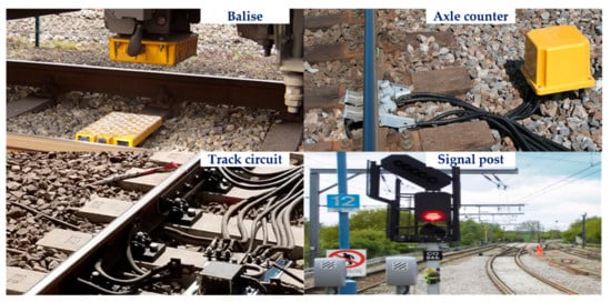
Figure 4. Track-side infrastructures.
3.2. On-Board Sensors
On-board sensors include tachometers, inertial sensors, satellite-based positioning systems, and other on-board sensors [49]. Several on-board sensors are shown in Figure 5. In terms of train positioning based on these sensors, all the components and computations parts are on-board, and in contrast to infrastructure-based localisation methods, it also requires a map of the railway tracks [50]. The track map contains the tracks’ information and connections, and the measurable features of the track, providing a reliable position estimation. There are multiple approaches to train localisation based on on-board sensors and a map, and they are different in terms of sensor types or combinations, processing methods, and evaluation scopes [50]. A combination of a Global Positioning System (GPS), Doppler measurements, and a track map is studied in [51].

Figure 5. On-board sensors: (a) stereo depth camera; (b) environmental camera; (c) IMU; (d) RTK-GPS; (e) 3D Lidar.
Much research has been done in the field of train positioning methods based on GPS. For instance, European Train Control systems (ETCS) level-3 use GPS especially for train integrity confirmation [52][53]. Due to the train’s complex environment, using only GPS cannot afford reliable position data in some specific scenarios such as tunnels, hilly regions, and urban canyons [54]. Therefore, multi-sensor fusion positioning methods have been proposed in this regard [55][56]. A fusion of GPS and Inertial Navigation System (INS) is widely used as a localisation system [57]. This system works properly when there is a continuous correction by GPS; otherwise, there is a cumulative position error caused by INS. In other words, if there is no GPS correction, using the Inertial Measurement Unit (IMU) alone for a long time will result in a huge offset. Therefore, more sensors and information sources are necessary to precisely and consistently locate the train, such as odometers, eddy-current sensors, Doppler velocity sensors and accelerometers, digital maps and wayside transponders such as RFID or balises, and other on-board equipment [58]. The necessity of augmenting GPS with other measurements for operational and safety reasons is discussed in [59][60].
A multi-sensor scheme that collects data from various sensors installed on the vehicle (specifically, an IMU and a GPS) and performs a Kalman-based filtering recursion is investigated in [61]. That study focused on solutions that could be used on every rail vehicle regardless of the ground equipment on the specific lines. In another study [62], an adaptive multi-sensor data fusion technique for the precise assessment of the train’s position and velocity, based on three on-board sensors—longitudinal accelerometer, odometer, and GPS receiver unit—is suggested. A localisation technique for railway vehicles, based on the fusion of tachometer and IMU and with the aim of performance enhancement in terms of speed and position estimation accuracy, is introduced in [63]. This fusion was thanks to Kalman filtering (KF) theory. Another piece of research [64] presents a particle filter-based localisation approach for a rail-guided robot. A particle filter was considered to integrate odometry with inertial measurements, laser scans, and image data. As a result, a rail map, a motion model, and a perception model were developed to implement a 1D estimation.
Dead-reckoning systems such as eddy current sensors [65][66], Doppler radar [67], Inertial Measurement Unit (IMU), and optical imaging [68] are applied for vehicle positioning based on estimating distance and direction of travel from a known fixed point. However, these systems lead to uncertainty due to inherent cumulative errors which are typically caused by wheel slippage, wear of wheels and mechanical parts, bias, and hysteresis, etc. [69]. Therefore, these sensors cannot be utilised alone for long periods of time in safety-critical applications such as collision avoidance and train automation [70], and need to be reset periodically to improve localisation accuracy. For this reason, whether they are used alone or in combination, they must be merged with GPS [71] or track-side markings such as RFID-type devices or balises [67]. The fusion of GNSS, inertial sensors, and odometry was examined in [72].
It is worth mentioning that current train-borne localisation systems using GNSS, odometers, and track maps have severe shortcomings concerning accuracy and reliability. The problem is that they cannot always determine immediately which of several parallel tracks the train is situated on. This is the most important prerequisite for the safety of railway vehicle control systems [73]. Therefore, lidar sensors are the most promising choice to complement those systems proposed in train localisation [74]. They are used for identifying large structures and environmental changes (e.g., exiting a tunnel or entering a station) based on a topological map of those features. It can be said that, in the case of train positioning, lidar is related to the topological landmark detection, as in the work of [43]. This information is then utilised to verify other sensors’ location estimates and reset dead-reckoning errors.
On-board train localisation from the perspective of safety assessment was investigated in [44]. The researchers attempted to answer the question of how an on-board train localisation system can be designed so that it ensures safe operations. They propose a generic approach that is not reliant on specific sensing devices. The system is based on three sources of information: a GNSS receiver, a velocity sensor, and a digital track map. Figure 6 represents the components of an on-board localisation system that fuses the incoming information from the on-board sensors. It determines the position of railway vehicle without relying on any trackside aids.
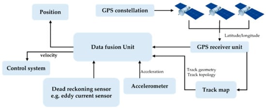
Figure 6. Main components of a railway vehicle positioning.
In another classification, Durazo Cardenas et al. [54] cited the positioning sensors based on the principles of the sensor’s technology. They gathered four types of general location systems: GNSS [75], radiolocation [76], proximity [77][78] and dead-reckoning systems. A summary of these sensors can be found in [54].
A number of on-board sensors and track-side infrastructure are compared with each other in terms of absolute and relative positioning, rate of frequency, long-term and short-term baseline, outage difficulties, and environmental impact. In this table, absolute localisation refers to a global localisation solution which relies on the GNSS constellations or landmarks to restore the position and orientation information with regard to a global reference frame [79]. Relative localisation refers to a local localisation technique which uses on-board sensors and kinematic models to estimate the robot’s pose relative to its initial pose [79]. Baseline is defined by the distance between the rover and a reference point [80]. For instance, in terms of applying GPS, baseline is about the vehicle and the base station. The length of the baseline varies between short, medium, and large [80]. Another parameter in this table is outage issue, which refers to the unavailability of a sensor for a period of time, which can be due to different reasons. For example, GPS could have an outage issue inside the tunnels, near the buildings, or in urban canyons, and so on [81]. The last parameter is environment impact, which includes any changes in the environment such as rain, snow, fog, or any natural change in the environment.
4. Sensor Hardware
As has been previously mentioned, one of the most important challenging tasks within any autonomous driving framework is localisation from data collected in real time. Therefore, accurate and reliable measurement of on-board systems plays a critical role for the vehicles moving on the railway track. There are various sensors for measuring the position and speed of railway vehicles. The most common ways include: tachometers, transponders, balises, INS, Doppler effect, and GPS [69]. A comparative survey highlighted benefits and drawbacks associated with different sensor types [82][83]. These sensors can be evaluated and classified according to several parameters, including cost, accuracy, reliability, sensitivity, coverage, speed of response, and availability [69]. Accurate and reliable odometry information may be achieved using a number of these sensors, whose redundant or complementary data are combined intelligently to produce more accurate and reliable information. In the following, each sensor is described briefly.
-
Tachometers:
Wheel angular speed sensors are widely diffused in railway applications due to their resilience and reliability. They are frequently employed as a principal form of speed measurement equipment. Through this type of sensor, when pure rolling conditions occur, the train speed can be simply estimated [84]. Various types of tachometers have been developed and applied, including optical, capacitive, active, and passive electromagnetic tachometers; however, the incremental optical tachometer is more accurate and efficient than the other types. A tachometer’s accuracy is usually impacted by a variety of sources of errors, including noises in mechanical and electrical parts, mechanical imperfections, wheel slip and slide, sampling frequency, and alteration in the wheel diameter as a result of wear and turning [69][84]. A number of approaches for correcting the position inaccuracy caused by slip and slide have been proposed and carried out, including correction by marginal distance, mutual correction of numerous axles, and frequent resetting of the position using transponders [85].
-
Transponders:
Passive and active transponders are track-based items that are used in conjunction with on-board odometers (integrating tachometers), representing a reliable method for measuring the position of a train [69]. They have been used by numerous railway operators. The transponders transmit a signal to the train-based receiver that includes information on their position and in some circumstances signaling information. Increasing the number of transponders along the track to reduce the positioning error results in higher costs and lower reliability in the system [69].
-
Balise:
A balise is an electronic beacon or transponder that is installed between railway tracks as part of an automated train protection (ATP) system. It provides the train a position reference as well as direction information. It is an example of a transponder fixed on the track to correct the position uncertainty that builds up within the train location subsystem over the time. Balises, as magnetically coupled transponders, do not require a steady energy source [86], and can be termed as passive. The balises are placed at approximately regular intervals, with the distance between them being determined based on two factors: the speed of the trains and complexity of the railway [87]. As it is important for the trains to stop precisely at stations, point zones, and buffer stops, up to eight balises are required at a minimum interval defined by the design [87]. In order to increase the possibility of balise detection by the train and decrease the possibility of the train failing to read a balise, the use of more than one balise in critical stopping locations is considered.
-
Doppler Radar:
Based on the principle of the Doppler frequency shift effect, Doppler radar can calculate the train’s immediate speed by analysing the frequency difference between the radar transmitted and reflected wave [88]. It is a non-contact sensor with two microwave antennas that gives accurate and consistent results independent of reflecting surface or vibration [89]. Compared to a tachometer, Doppler radar is found to provide more accurate data [90]. Heide et al. [91], by doing a number of experiments, demonstrated that the use of a coded 24 GHz Doppler radar can provide high precision data (within 20 db) for vehicle position and speed measurement. On the other hand, Malvezzi et al. [92], while discussing odometric estimation for a train protection system, stated that Doppler radar output is often affected by noise and systematic errors. Mirabadi et al. [69] also stated this issue and identified sources of errors including very smooth reflective surface and change in radiation angle owing to acceleration and braking action, vibration, and bias error.
-
Inertial Navigation Systems (INS):
INSs are navigational systems capable of measuring the acceleration, speed, and position of a moving train along the stable axes [79]. An INS is a system that is basically composed of at least three gyros and three accelerometers to derive a navigation solution. The accelerometer will measure the acceleration of the vehicle by integrating the acceleration signals both speed and position data. On the other side, gyroscopes are used in order to measure an angular rotation of the vehicle [93]. They can be used to obtain accurate information of the trajectory of the train in a horizontal and vertical direction. Unlike tachometers, which depend on wheel rotations, the INS system is self-contained, and this is a major advantage of this system. They do not need a line of sight such as GPS. They can be used in any weather condition and environment, both underground or overground.
-
Global Positioning System (GPS):
GPS is a satellite-based radio navigation technology which is the core functionality for any navigation system [79] and provides absolute position information with a known ratio of error. The fundamental advantage of GPS is its long-term stability and its resistance to the accumulation of errors over time. GPS is mainly utilised for more than simple outdoor navigational tasks and it is effective in areas with a clear view of the sky. However, GPS sensors are ineffective in certain areas such as tunnels, forests, underground, and underwater spaces [94]. They also have outages caused by satellite signal blockage, occasional high noise content, multipath effects, low bandwidth, and interference or jamming. Common GPS sensors are utilised for positioning, which has an accuracy of 10 m. This does not provide sufficient accuracy [95] for train localisation.
-
Light Detection and Ranging (LiDAR):
The lidar sensor is an optical device which uses laser light pulses to gather information from surfaces in the form of “points” (3D coordinates). Compared with cameras, the lidar sensor operates more reliably at different weather conditions and is less influenced by the lighting or weather conditions due to the infrared laser that provides an adequate illumination. Therefore, even in tunnels or under bridges, appropriate measurements can be obtained [73]. LiDAR sensors are also widely deployed in railway applications for different reasons, including object detection and collision avoidance, and in level crossings for detecting whether there are passenger cars, trucks, or people [96]. In [74], the application of LiDAR in a train-borne localisation system is investigated. It is mentioned that position measurements at turnouts remain ambiguous. The combination of GPS, velocity sensors, and digital track map are not capable of addressing the challenges of unavailability of GPS in some parts of environments, and velocity sensors can fail to specify which branch at a turnout is taken by a train. In [97], a 2D Lidar is deployed in an underground railway environment to specify high-speed train localisation.
-
Visual sensor:
There are various publications related to the deployment of vision sensors in railway inspection and maintenance applications such as the detection of missing bolts, railhead wear, and other surface geometry inconsistencies [98]. A vision system consisting of a monocular thermal camera mounted on a train for detecting the rails in imagery as well as for detecting anomalies on the railway is pointed out in [99]. In another piece of research, a prototype system for railway object detection, installed in the cab of a train, is presented [100]. The aforementioned system consists of a single camera that acquires images of the railway scene in front of the train and a near-infrared laser primarily used to add illumination to the area the camera is directed at when the light is insufficient. A summary of the publications describing traditional computer vision approaches are described in [101]. The advantages of cameras over other active sensors are high data density and visual information, enabling the detection of the boundaries of objects and the classification of these objects precisely.
5. Sensor Fusion
5.1. Sensor Fusion Techniques
Sensor fusion is an essential aspect of most autonomous systems; therefore, various types of algorithms and methodologies have been widely researched in recent years and are now well-established in the literature. Due to the diversity and variety of fusion algorithms proposed in the literature, getting the current state-of-the-art fusion techniques and algorithms is a demanding task, according to a recent study [102]. Recently, several reviews on the topic of multi-sensor fusion have been published, with some describing the architectural structure and sensor technologies in AV [103][104], and others focusing on processing stages such as sensor calibration, state estimation, object and tracking [105], [106], or detailing techniques for multi-sensor fusion, such as deep learning-based approaches [107][108].
A review study in [107] divided these techniques and algorithms into two categories: classical sensor fusion algorithms and deep learning sensor fusion algorithms. On the one hand, classical sensor fusion algorithms, such as knowledge-based approaches, statistical methods, probabilistic methods, and so on, fuse sensor data using theories of uncertainty from data flaws, such as inaccuracy and uncertainty [109]. Deep learning sensor fusion techniques, on the other hand, entail the creation of numerous multi-layer networks that enable them to process raw data and extract features in order to accomplish difficult and sophisticated tasks such as object detection. Deep learning is a subset of artificial intelligence and machine learning that can be considered as an advancement of neural networks [107]. The quantity of research into deep learning sensor fusion algorithms in autonomous vehicles (AV) has increased noticeably. Convolutional Neural Network (CNN) and Recurrent Neural Network (RNN) algorithms are among the most used in autonomous vehicle perception systems. To increase the real-time performance of object detection, [110] suggested advanced weighted-mean You Only Look Once (YOLO) CNN algorithms to merge RGB camera and LiDAR point cloud data. Some other examples of deep learning-based sensor fusion algorithms include ResNet (i.e., Residual Networks), a residual learning framework that facilitates deep networks training [111]; SSD (i.e., Single-Shot Multibox Detector), which discretizes bounding boxes into a set of boxes with different sizes and aspect ratios per feature map location to detect objects with variant sizes [112]; and CenterNet [113], which represents the state-of-the-art monocular camera 3D object detection algorithm.
Despite the vast quantity of research which has been done in the field of environment perception with deep learning approaches, the application of deep learning to localisation has not received the same level of attention or maturity. As a result, there is a lot of promise for using deep learning algorithms, especially RNN, to improve sequential localisation data. Learning algorithms may in the future provide an end-to-end deep learning localisation and mapping system that avoids feature modelling and data association, reducing errors and uncertainties associated with unmodeled dynamics and imprecise modelling [107].
5.2. Sensor Fusion Algorithms for Vehicle-Based Localisation on the Railway Track
As has been mentioned, new approaches in instrumentation, technology, engineering, and, in particular, sensor fusion, have opened up new paths for achieving better reliability and accuracy in measurement. Integration of several sensors for speed and position measurement is the concept which has attracted much interest in industry and research departments [92][114]. Fusing measurements from different independent sensors which have different kinds of input/output attributes and characteristics will extract the best information in terms of accuracy and reliability. Therefore, when multi-sensor data fusion techniques are included in the system, the navigation system becomes more robust. In other words, it can increase the robustness of the system against possible faults of each element it is composed of. This can help railway engineers to achieve higher safety.
The use of multi-sensor data fusion techniques have also gained much popularity and been found to be advantageous when used in intelligent transportation systems [115][116]. Integrating different position and speed sensors will give more information about the system conditions for monitoring and control tasks [69]. The combination of sensors should be chosen in a way which optimizes coverage of multiple aspects, including availability, reliability, speed of response, cost, and accuracy of the system, besides providing a better on-board measurement system. For instance, integrating tachometer and transponder sensors, a type of primitive sensor fusion, will increase the accuracy level by re-initiating the position at some fixed points, but it still does not overcome errors caused by slip and slide between two transponders [117]. A localisation algorithm for increasing the accuracy of the odometric estimation, especially in critical adhesion conditions, based on sensor fusion between tachometers and inertial measurement unit, is suggested in [84]. A data fusion technique is proposed in [62] for a train localisation system consisting of three on-board sensors, namely, longitudinal accelerometer, odometer, and GPS receiver unit. Wang et al. [118] proposed a train positioning method which fuses vison and millimeter-wave radar data. The proposed framework includes the loop closure detection part which eliminates the cumulative error when the train detects a key position, and the radar-based odometry part which can realize the positioning of the train on the whole railway line.
In [66], a hybrid framework for locating trains travelling on track routes based on GNSS and eddy current sensor device, implemented by an Extended Kalman Filter method, is proposed. This positioning system performs a robust localisation even in the case of noise or when a sensor fault occurs. In another piece of research [71], two different fusion approaches which use two different system models to approximate the kinematics of train-borne location system are investigated. These are an eddy current sensor device providing the train velocity and a GNSS delivering the absolute position. The first fusion is based on a polar coordinate system model, whereas the second fusion approach uses two cartesian system models with the ability to switch between these models. Evaluating the fusion approaches shows that in case of GPS failures, the first fusion approach with its system model in polar coordinates can propagate the train kinematics more adequately and thus achieve a better performance than the second fusion approach.
Another common fusion approach is based on the integration of GPS and INSs, which typically results in a drift in the estimation of the vehicle speed and position [63]. To address this problem, a filter is used aimed at decreasing the difference between the data output signals coming from INS and another one, e.g., GPS [95]. Due to GPS signal degradation in some parts of the environment, including indoor environments, dense forests, and near the tall buildings, it is necessary to consider alternative solutions to compensate this outage, for instance a fusion of tachometer and IMU (Inertial Measurement Unit).
Overall, maintenance is critical in the railway industry since it ensures both safety and profitability. In the railway industry, there has been a tendency toward increased automation and productivity. As a result, it has become larger, more expensive, and more technically complicated than ever. The track infrastructure is a significant part of the railway system, and its upkeep is a key financial consideration in technical, administrative, and managerial decisions
References
- Using Analytics to Get European Rail Maintenance on Track|McKinsey. Available online: https://www.mckinsey.com/industries/public-and-social-sector/our-insights/using-analytics-to-get-european-rail-maintenance-on-track (accessed on 22 April 2022).
- Report from the Eim-Efrtc-Cer Working Group on Market Strategies for Track Maintenance & Renewal Follow up to the Conclusions of Ec Innotrack Project/Wp5. Available online: https://www.cer.be/sites/default/files/publication/2353_7473-11_MARKET_STRATEGY_A4_FINAL.pdf (accessed on 22 April 2022).
- Lidén, T. Railway infrastructure maintenance-A survey of planning problems and conducted research. Transp. Res. Procedia 2015, 10, 574–583.
- Rail Track Maintenance: A Career Explained-Rail Futures. Available online: https://railfutures.co.uk/rail-track-maintenance-a-career-explained/ (accessed on 22 April 2022).
- Cost Benchmarking of Network Rail’s Maintenance and renewals Expenditure Annual Report: Year 2 of control Period 6. 2021. Available online: https://www.orr.gov.uk/sites/default/files/2021-07/cost-benchmarking-of-network-rail-annual-report-year-2-of-cp6.pdf (accessed on 22 April 2022).
- Predictive Maintenance of Rail Infrastructure. Available online: https://www.brunel.ac.uk/research/projects/predictive-maintenance-of-rail-infrastructure (accessed on 22 April 2022).
- Parker, L.E.; Draper, J.V. Robotics applications in maintenance and repair. Handb. Ind. Robot. 1998, 2, 1023–1036.
- Mahfuz, N.; Dhali, O.A.; Ahmed, S.; Nigar, M. Autonomous railway crack detector robot for bangladesh: SCANOBOT. In Proceedings of the 2017 IEEE Region 10 Humanitarian Technology Conference (R10-HTC), Dhaka, Bangladesh, 21–23 December 2017; pp. 524–527.
- James, J.; Wilson, J.; Jetto, J.; Thomas, A.; Dhahabiya, V.K. Intelligent track cleaning robot. In Proceedings of the 2016 IEEE International Conference on Mechatronics and Automation, Harbin, China, 7–10 August 2016; pp. 332–337.
- Dhiyaneswaran, J.; Vimal Raja, M.; Ashok Kumar, B.; Muthu Kumaran, C.B. Design and fabrication of railway track cleaning bot. Mater. Today Proc. 2021, 37, 2677–2680.
- Menendez, E.; Victores, J.G.; Montero, R.; Martínez, S.; Balaguer, C. Tunnel structural inspection and assessment using an autonomous robotic system. Autom. Constr. 2018, 87, 117–126.
- Kitamura, A.; Namekawa, T.; Hiramatsu, K.; Sankai, Y. Operating Manipulator Arm by Robot Suit HAL for Remote In-Cell Equipment Maintenance. Nucl. Technol. 2013, 184, 310–319.
- Errico, S.D. Simulation of a railway asset maintenance robot. Cranfield Univ. 2018, 44, 750111.
- Martland, C.D. Analysis of the potential impacts of automation and robotics on locomotive rebuilding; Analysis of the potential impacts of automation and robotics on locomotive rebuilding. IEEE Trans. Eng. Manag. 1987, 34, 92–100.
- Robotics and Industrial AI for Track Maintenance Global Railway Review. Available online: https://www.globalrailwayreview.com/article/114137/robotics-and-industrial-ai-track-maintenance/ (accessed on 22 April 2022).
- Esveld, C. Modern Railway Track, 2th edition. MRT-Productions. 2001. Available online: http://www.esveld.com/Documents/MRT_Selection.pdf (accessed on 22 April 2022).
- Sedghi, M.; Kauppila, O.; Bergquist, B.; Vanhatalo, E.; Kulahci, M. A taxonomy of railway track maintenance planning and scheduling: A review and research trends. Reliab. Eng. Syst. Saf. 2021, 215, 107827.
- The Importance of Rail and Track Maintenance-RWB Group Blog. Available online: https://www.rwbgroup.co.uk/the-importance-of-rail-and-track-maintenance/ (accessed on 22 April 2022).
- Vithanage, R.K.W.; Harrison, C.S.; Desilva, A.K.M. Importance and applications of robotic and autonomous systems (RAS) in railway maintenance sector: A review. Computers 2019, 8, 56.
- Vithanage, R.K.W.; Harrison, C.S.; Desilva, A.K.M.M. Enhance 3D Point Cloud Accuracy Through Supervised Machine Learning for Automated Rolling Stock Maintenance: A Railway Sector Case Study. In Proceedings of the 2018 International Conference on Computing, Electronics & Communications Engineering (iCCECE), Southend, UK, 16–17 August 2018.
- Railroad-Track Maintenance|Britannica. Available online: https://www.britannica.com/technology/railroad/Track-maintenance (accessed on 22 April 2022).
- Trivedi, M.M.; Ng, K.C.; Lassiter, N.; Capella, R. New generation of multirobot systems. Proc. IEEE Int. Conf. Syst. Man Cybern. 1998, 4, 3342–3346.
- Rowshandel, H.; Nicholson, G.L.; Davis, C.L.; Roberts, C. An integrated robotic system for automatic detection and characterisation of rolling contact fatigue cracks in rails using an alternating current field measurement sensor. Proc. Inst. Mech. Eng. Part F J. Rail Rapid Transit 2013, 227, 310–321.
- Rowshandel, H. The Development of an Autonomous robotic Inspection System to Detect and Characterise Rolling Contact Fatigue Cracks in Railway Track. Available online: http://etheses.bham.ac.uk/4821/ (accessed on 22 April 2022).
- Autonomous Inspection Trolley for Better Train Track Maintenance|AutoScan Project|Results in Brief|H2020|CORDIS|European Commission. Available online: https://cordis.europa.eu/article/id/250858-autonomous-inspection-trolley-for-better-train-track-maintenance (accessed on 22 April 2022).
- Our Platform–RailPod, Inc. Available online: https://rail-pod.com/?page_id=2527 (accessed on 22 April 2022).
- Yunus, S.; Mehmet, K.; Erhan, A. Condition Monitoring Approach Using 3DModelling of Railway Tracks with Laser Cameras. Conference: International Conference on Advanced Technology & Sciences (ICAT’16). Available online: http://www.icatsconf.org/uploads/files2/procedings_v4.pdf (accessed on 22 April 2022).
- Madejski, J. Autonomous track geometry diagnostics system. J. Mater. Process. Technol. 2004, 157–158, 194–202.
- Wang, L.; Zhang, B.; Wu, J.; Xu, H.; Chen, X.; Na, W. Computer vision system for detecting the loss of rail fastening nuts based on kernel two-dimensional principal component–two-dimensional principal component analysis and a support vector machine. Proc. Inst. Mech. Eng. Part F J. Rail Rapid Transit 2015, 230, 1842–1850.
- Gibert, X.; Patel, V.M.; Chellappa, R. Robust fastener detection for autonomous visual railway track inspection. In Proceedings of the 2015 IEEE Winter Conference on Applications of Computer Vision, Waikoloa, HI, USA, 5–9 January 2015.
- Al-Douri, Y.K.; Tretten, P.; Karim, R. Improvement of railway performance: A study of Swedish railway infrastructure. J. Mod. Transp. 2016, 24, 22–37.
- Track-Network Rail. Available online: https://www.networkrail.co.uk/running-the-railway/looking-after-the-railway/track/ (accessed on 22 April 2022).
- Dhillon, B.S. Engineering Maintenance: A Modern Approach; CRC Press: Boca Raton, FL, USA, 2002; ISBN 9781420031843.
- Shang, H.; Bérenguer, C.; Andrews, J. Delayed maintenance modelling considering speed restriction for a railway section. Proc. Inst. Mech. Eng. Part O J. Risk Reliab. 2017, 231, 411–428.
- Sharma, S.; Cui, Y.; He, Q.; Mohammadi, R.; Li, Z. Data-driven optimization of railway maintenance for track geometry. Transp. Res. Part C Emerg. Technol. 2018, 90, 34–58.
- Comino, F. Cobots for Maintenance in the Railway Industry; Cranfield University: Cranfield, UK, 2018.
- Track Treatment Fleet-Network Rail. Available online: https://www.networkrail.co.uk/running-the-railway/looking-after-the-railway/our-fleet-machines-and-vehicles/track-treatment-fleet/ (accessed on 22 April 2022).
- Cannon, D.F.; Edel, K.O.; Grassie, S.L.; Sawley, K. Rail defects: An overview. Fatigue Fract. Eng. Mater. Struct. 2003, 26, 865–886.
- Seasonal Track Treatment and Weather Support Fleet-Network Rail. Available online: https://www.networkrail.co.uk/running-the-railway/looking-after-the-railway/our-fleet-machines-and-vehicles/seasonal-track-treatment-and-weather-support-fleet/ (accessed on 22 April 2022).
- High Output machines-Network Rail. Available online: https://www.networkrail.co.uk/running-the-railway/looking-after-the-railway/our-fleet-machines-and-vehicles/high-output/high-output-machines/ (accessed on 22 April 2022).
- Heirich, O. Localization of Trains and Mapping of Railway Tracks. Ph.D. Thesis, Technische Universität München, München, Germany, 2020.
- Requirements for Safety Relevant Positioning Applications in Rail Traffic–A Demonstrator for a Train Borne Navigation Platform Called ‘DemoOrt’. Available online: https://www.researchgate.net/publication/224797887_Requirements_for_Safety_Relevant_Positioning_Applications_in_Rail_Traffic_-_A_Demonstrator_for_a_Train_Borne_Navigation_Platform_Called_DemoOrt (accessed on 22 April 2022).
- Albrecht, T.; Lüddecke, K.; Zimmermann, J. A precise and reliable train positioning system and its use for automation of train operation. In Proceedings of the 2013 IEEE International Conference on Intelligent Rail Transportation Proceedings, Beijing, China, 30 August–1 September 2013.
- Lauer, M.; Stein, D. A Train Localization Algorithm for Train Protection Systems of the Future. IEEE Trans. Intell. Transp. Syst. 2015, 16, 970–979.
- Hutchinson, M.; Marais, J.; Masson, E.; Mendizabal, J.; Meyer, M.; Hutchinson, M.; Marais, J.; Masson, E.; Mendizabal, J.; Meyer, M. Precise and reliable localization as a core of railway automation (Rail 4.0). International Congress on High-Speed Rail: Technologies and long Term Impacts. 2017. Available online: https://hal.archives-ouvertes.fr/hal-01662758 (accessed on 22 April 2022).
- European Railway Agency. Railway Safety Performance in the European Union 2008. 2008, Volume 44. Available online: https://www.era.europa.eu/sites/default/files/library/docs/safety_interoperability_progress_reports/railway_safety_performance_2016_en.pdf (accessed on 22 April 2022).
- Temple, W.G.; Anh Tran, B.N.; Chen, B.; Kalbarczyk, Z.; Sanders, W.H. On Train Automatic Stop Control Using Balises: Attacks and a Software-Only Countermeasure. In Proceedings of the 2017 IEEE 22nd Pacific Rim International Symposium on Dependable Computing (PRDC), Christchurch, New Zealand, 22–25 January 2017.
- Zhou, J.; Xiao, H.; Jiang, W.; Bai, W.; Liu, G. Automatic subway tunnel displacement monitoring using robotic total station. Meas. J. Int. Meas. Confed. 2020, 151, 107251.
- Otegui, J.; Bahillo, A.; Lopetegi, I.; Diez, L.E. A Survey of Train Positioning Solutions. IEEE Sens. J. 2017, 17, 6788–6797.
- Heirich, O.; Siebler, B.; Sand, S.; Lehner, A.; Crespillo, O.G. Measurement methods for train localization with onboard sensors. In Proceedings of the 2020 European Navigation Conference (ENC), Dresden, Germany, 23–24 November 2020.
- Fouque, C.; Bonnifait, P. Matching raw GPS measurements on a navigable map without computing a global position. IEEE Trans. Intell. Transp. Syst. 2012, 13, 887–898.
- Marais, J.; Beugin, J.; Berbineau, M. A Survey of GNSS-Based Research and Developments for the European Railway Signaling. IEEE Trans. Intell. Transp. Syst. 2017, 18, 2602–2618.
- Hynek, M. Galileo as an Instrument of Unification Galileo as an Instrument of Unification of the European Railway Transport of the European Railway Transport. Railway Infrastructure Administration. 2008. Available online: http://www.telematika.cz/download/doc/gufd_08_ar01_02_Mocek_SZDC.pdf (accessed on 22 April 2022).
- Durazo-Cardenas, I.; Starr, A.; Tsourdos, A.; Bevilacqua, M.; Morineau, J. Precise vehicle location as a fundamental parameter for intelligent selfaware rail-track maintenance systems. Procedia CIRP 2014, 22, 219–224.
- Wang, J.; Liu, D.; Jiang, W.; Lu, D. Evaluation on loosely and tightly coupled GNSS/INS vehicle navigation system. In Proceedings of the 2017 International Conference on Electromagnetics in Advanced Applications (ICEAA), Verona, Italy, 11–15 September 2017; pp. 892–895.
- Kim, K.; Seol, S.; Kong, S.-H. High-speed Train Navigation System based on Multi-sensor Data Fusion and Map Matching Algorithm. Int. J. Control. Autom. Syst. 2015, 13, 503–512.
- Zhang, T.; Xu, X. A new method of seamless land navigation for GPS/INS integrated system. Measurement 2012, 45, 691–701.
- Stadimann, B. Automation of operational train control on regional branch lines by a basic train control. In Proceedings of the 2006 IEEE Intelligent Transportation Systems Conference, Toronto, ON, Canada, 17–20 September 2006; pp. 50–54.
- Toro, F.G.; Becker, U.; Fuentes, D.E.D.; Lu, D.; Tao, W. Accuracy Analysis for GNSS-based Urban Land Vehicle Localisation System. IFAC-PapersOnLine 2016, 49, 191–196.
- Mázl, R.; Přeučil, L. Sensor data fusion for inertial navigation of trains in GPS-dark areas. In Proceedings of the IEEE IV2003 Intelligent Vehicles Symposium, Columbus, OH, USA, 9–11 June 2003; pp. 345–350.
- Selvi, D.; Meli, E.; Allotta, B.; Rindi, A.; Capuozzo, A.; Rucher, L. Feasibility Analysis of Positioning and Navigation Strategies for Railway and Tramway Applications. IFAC-PapersOnLine 2020, 53, 15680–15686.
- Malakar, B.; Roy, B.K. Train localization using an adaptive multisensor data fusion technique. Transport 2019, 34, 508–516.
- Allotta, B.; D’Adamio, P.; Malvezzi, M.; Pugi, L.; Ridolfi, A.; Vettori, G. A localization algorithm for railway vehicles. In Proceedings of the 2015 IEEE International Instrumentation and Measurement Technology Conference (I2MTC), Pisa, Italy, 11–14 May 2015.
- Carvalho, G.P.S.; Costa, R.R. Localization of an Autonomous Rail-Guided Robot Using Particle Filter. IFAC-PapersOnLine 2017, 50, 5642–5647.
- Hensel, S.; Hasberg, C.; Stiller, C. Probabilistic rail vehicle localization with eddy current sensors in topological maps. IEEE Trans. Intell. Transp. Syst. 2011, 12, 1525–1536.
- Boehringer, F. Train location based on fusion satellite and train-borne sensor data. Locat. Serv. Navig. Technol. 2003, 5084, 76.
- Acharya, A.; Sadhu, S.; Ghoshal, T.K. Train localization and parting detection using data fusion. Transp. Res. Part C Emerg. Technol. 2011, 19, 75–84.
- Shenton, R. Train positioning using video Odometry. ESGI100 Oxford. 2014. Available online: https://miis.maths.ox.ac.uk/miis/672/1/Report.pdf (accessed on 22 April 2022).
- Mirabadi, A.; Mort, N.; Schmid, F. Application of sensor fusion to railway systems. In Proceedings of the 1996 IEEE/SICE/RSJ International Conference on Multisensor Fusion and Integration for Intelligent Systems (Cat. No. 96TH8242), Washington, DC, USA, 8–11 December 1996; pp. 185–192.
- Hasberg, C.; Hensel, S.; Stiller, C. Simultaneous localization and mapping for path-constrained motion. IEEE Trans. Intell. Transp. Syst. 2012, 13, 541–552.
- Böhringer, F.; Geistler, A. Comparison between different fusion approaches for train-borne location systems. IEEE Int. Conf. Multisens. Fusion Integr. Intell. Syst. 2006, 267–272.
- Albanese, A.; Marradi, L. The RUNE project: The integrity performances of GNSS-based railway user navigation equipment. In Proceedings of the ASME/IEEE 2005 Joint Rail Conference, Pueblo, CO, USA, 16–18 March 2005.
- Stein, D.; Lauer, M.; Spindler, M. An analysis of different sensors for turnout detection for train-borne localization systems. WIT Trans. Built Environ. 2014, 135, 827–838.
- Stein, D.; Spindler, M.; Kuper, J.; Lauer, M. Rail detection using lidar sensors. Int. J. Sustain. Dev. Plan. 2016, 11, 65–78.
- Zygowicz, R.J.; Beimborn, E.A.; Peng, Z.-R.; Ocatania, S. State of the Art in Automatic Vehicle Location Systems. 2008. Available online: https://www4.uwm.edu/cuts/its/avlapa.pdf (accessed on 22 April 2022).
- José, A.; Santos, D.; Soares, R.; Manuel, F.; Redondo, A.; Carvalho, N.B. Tracking Trains via Radio Frequency Systems. IEEE Trans. Intell. Transp. Syst. 2005, 6, 244–258.
- Bantin, C.C.; Luttgen, A.; Schwellnus, C.; Kinio, W. Precise positioning of RFID tags using a phased array antenna. In Proceedings of the 2012 IEEE International Symposium on Antennas and Propagation, Chicago, IL, USA, 8–14 July 2012.
- Patra, A.P.; Kumar, U. Availability analysis of railway track circuits. Proc. Inst. Mech. Eng. Part F J. Rail Rapid Transit 2010, 224, 169–177.
- Goel, P.; Roumeliotis, S.I.; Sukhatme, G.S. Robust localization using relative and absolute position estimates. IEEE Int. Conf. Intell. Robot. Syst. 1999, 2, 1134–1140.
- Okorocha, V.; Olajugba, O. Comparative Analysis of Short, Medium and Long Baseline Processing in the Precision of GNSS Positioning. In Proceedings of the FIG Congress 2014, Kuala Lumpur, Malaysia, 16–21 June 2014; Available online: http://www.fig.net/resources/proceedings/fig_proceedings/fig2014/papers/ts09b/TS09B_okorocha_olajugba_7005.pdf (accessed on 22 April 2022).
- Li, N.; Guan, L.; Gao, Y.; Du, S.; Wu, M.; Guang, X.; Cong, X. Indoor and outdoor low-cost seamless integrated navigation system based on the integration of INS/GNSS/LIDAR system. Remote Sens. 2020, 12, 3271.
- Chang, L.; Niu, X.; Liu, T. Gnss/imu/odo/lidar-slam integrated navigation system using imu/odo pre-integration. Sensors 2020, 20, 4702.
- Kuutti, S.; Fallah, S.; Katsaros, K.; Dianati, M.; Mccullough, F.; Mouzakitis, A. A Survey of the State-of-the-Art Localization Techniques and Their Potentials for Autonomous Vehicle Applications. IEEE Internet Things J. 2018, 5, 829–846.
- Malvezzi, M.; Vettori, G.; Allotta, B.; Pugi, L.; Ridolfi, A.; Rindi, A. A localization algorithm for railway vehicles based on sensor fusion between tachometers and inertial measurement units. Proc. Inst. Mech. Eng. Part F J. Rail Rapid Transit 2014, 228, 431–448.
- Mirabadi, A.; Khodadadi, A. Slip and slide detection and compensation for odometery system, using adaptive fuzzy kalman filter. Sens. Lett. 2009, 7, 84–90.
- Sharma, R.; Lourde, R.M. Crosstalk reduction in balise and infill loops in automatic train control. In Proceedings of the 2007 11th International Conference on Intelligent Engineering Systems, Budapest, Hungary, 29 June–2 July 2007.
- Moreno García-Loygorri, J.; Pérez-Yuste, A.; Briso, C.; Berbineau Alain Pirovano, M.; Mendizábal, J. Communication Technologies for Vehicles. 2018. Available online: http://www.springer.com/series/7411 (accessed on 22 April 2022).
- Zhan, X.; Mu, Z.H.; Kumar, R.; Shabaz, M. Research on speed sensor fusion of urban rail transit train speed ranging based on deep learning. Nonlinear Eng. 2021, 10, 363–373.
- Bazant, L.; Toma, A.; Mocek, H. Description of methodology for data record sorting and saving. Satell. Technol. Adv. Railw. Signal. 2017, 114.
- Mirabadi, A.; Mort, N.; Schmid, F. Design of fault tolerant train navigation systems. Proc. Am. Control Conf. 1999, 1, 104–108.
- Heide, P.; Magori, V.; Schwarte, R. Coded 24 GHz Doppler radar sensors: A new approach to high-precision vehicle position and ground-speed sensing in railway and automobile applications. In Proceedings of the IEEE NTC, Conference Proceedings Microwave Systems Conference, Orlando, FL, USA, 17–19 May 1995; pp. 101–104.
- Malvezzi, M.; Allotta, B.; Rinchi, M. Odometric estimation for automatic train protection and control systems. Veh. Syst. Dyn. 2011, 49, 723–739.
- Alatise, M.B.; Hancke, G.P. A Review on Challenges of Autonomous Mobile Robot and Sensor Fusion Methods. IEEE Access 2020, 8, 39830–39846.
- Liu, Y.; Bao, Y. Review of electromagnetic waves-based distance measurement technologies for remote monitoring of civil engineering structures. Meas. J. Int. Meas. Confed. 2021, 176, 109193.
- Bertran, E.; Delgado-Penín, J.A. On the use of GPS receivers in railway environments. IEEE Trans. Veh. Technol. 2004, 53, 1452–1460.
- Blog-LiDAR Sensing Applications in the Railroad Industry-LeddarTech. Available online: https://leddartech.com/blog-lidar-sensing-applications-in-the-railroad-industry/ (accessed on 22 April 2022).
- Daoust, T.; Pomerleau, F.; Barfoot, T.D. Light at the end of the tunnel: High-speed lidar-based train localization in challenging underground environments. In Proceedings of the 2016 13th Conference on Computer and Robot Vision (CRV), Victoria, BC, Canada, 1–3 June 2016; pp. 93–100.
- Liu, S.; Wang, Q.; Luo, Y. A review of applications of visual inspection technology based on image processing in the railway industry. Transp. Saf. Environ. 2019, 1, 185–204.
- Berg, A.; Öfjäll, K.; Ahlberg, J.; Felsberg, M. Detecting Rails and Obstacles Using a Train-Mounted Thermal Camera. Lect. Notes Comput. Sci. 2015, 9127, 492–503.
- Ye, T.; Zhang, Z.; Zhang, X.; Zhou, F. Autonomous Railway Traffic Object Detection Using Feature-Enhanced Single-Shot Detector. IEEE Access 2020, 8, 145182–145193.
- Ristić-Durrant, D.; Franke, M.; Michels, K. A Review of Vision-Based On-Board Obstacle Detection and Distance Estimation in Railways. Sensors 2021, 21, 3452.
- Brena, R.F.; Aguileta, A.A.; Trejo, L.A.; Molino-Minero-Re, E.; Mayora, O. Choosing the best sensor fusion method: A machine-learning approach. Sensors 2020, 20, 2350.
- Wang, Z.; Wu, Y.; Niu, Q. Multi-Sensor Fusion in Automated Driving: A Survey. IEEE Access 2020, 8, 2847–2868.
- Velasco-Hernandez, G.; Yeong, D.J.; Barry, J.; Walsh, J. Autonomous Driving Architectures, Perception and Data Fusion: A Review. In Proceedings of the 2020 IEEE 16th International Conference on Intelligent Computer Communication and Processing (ICCP), Cluj-Napoca, Romania, 3–5 September 2020.
- Jusoh, S.; Almajali, S. A Systematic Review on Fusion Techniques and Approaches Used in Applications. IEEE Access 2020, 8, 14424–14439.
- Castanedo, F. A review of data fusion techniques. Sci. World J. 2013, 2013, 704504.
- Fayyad, J.; Jaradat, M.A.; Gruyer, D.; Najjaran, H. Deep learning sensor fusion for autonomous vehicle perception and localization: A review. Sensors 2020, 20, 4220.
- Kuutti, S.; Bowden, R.; Jin, Y.; Barber, P.; Fallah, S. A Survey of Deep Learning Applications to Autonomous Vehicle Control. IEEE Trans. Intell. Transp. Syst. 2021, 22, 712–733.
- Yeong, D.J.; Velasco-hernandez, G.; Barry, J.; Walsh, J. Sensor and sensor fusion technology in autonomous vehicles: A review. Sensors 2021, 21, 2140.
- Kim, J.; Kim, J.; Cho, J. An advanced object classification strategy using YOLO through camera and LiDAR sensor fusion; An advanced object classification strategy using YOLO through camera and LiDAR sensor fusion. In Proceedings of the 2019 13th International Conference on Signal Processing and Communication Systems (ICSPCS), Gold Coast, QLD, Australia, 16–18 December 2019.
- He, K.; Zhang, X.; Ren, S.; Sun, J. Deep Residual Learning for Image Recognition. Available online: http://image-net.org/challenges/LSVRC/2015/ (accessed on 22 April 2022).
- Liu, W.; Anguelov, D.; Erhan, D.; Szegedy, C.; Reed, S.; Fu, C.-Y.; Berg, A.C. SSD: Single Shot MultiBox Detector. In Proceedings of the European Conference on Computer Vision, Amsterdam, The Netherlands, 11–14 October 2016; pp. 21–37.
- Zhou, X.; Wang, D.; Krähenbühl, P. Objects as Points. arXiv 2019, arXiv:1904.07850.
- Jwo, D.-J.; Weng, T.-P. An Adaptive Sensor Fusion Method with Applications in Integrated Navigation. J. Navig. 2008, 61, 705–721.
- Khaleghi, B.; Khamis, A.; Karray, F.O.; Razavi, S.N. Multisensor data fusion: A review of the state-of-the-art. Inf. Fusion 2013, 14, 28–44.
- Kong, L.; Peng, X.; Chen, Y.; Wang, P.; Xu, M. Multi-sensor measurement and data fusion technology for manufacturing process monitoring: A literature review. Int. J. Extrem. Manuf. 2020, 2, 022001.
- Allotta, B.; D’Adamio, P.; Malvezzi, M.; Pugi, L.; Ridolfi, A.; Rindi, A.; Vettori, G. An innovative localisation algorithm for railway vehicles. Veh. Syst. Dyn. 2014, 52, 1443–1469.
- Wang, Z.; Yu, G.; Zhou, B.; Wang, P.; Wu, X. A Train Positioning Method Based-On Vision and Millimeter-Wave Radar Data Fusion. IEEE Trans. Intell. Transp. Syst. 2021, 23, 4603–4613.
More