3-D surgical planning for restorative osteotomy is costly and time-consuming because surgeons need to be helped from commercial companies to get 3-D printed bones. However, practitioners can save time and keep the cost to a minimum by utilizing free software and establishing their 3-D printers locally. Surgical planning for the corrective osteotomy of antebrachial growth deformities (AGD) is challenging for several reasons (the nature of the biapical or multiapical conformational abnormalities and lack of a reference value for the specific breed). Pre-operative planning challenges include: a definite description of the position of the center of rotation of angulation (CORA) and proper positioning of the osteotomies applicable to the CORA. In the present study, we demonstrated an accurate and reproducible bone-cutting technique using patient-specific instrumentations (PSI) 3-D technology. The results of the location precision showed that, by using PSIs, the surgeons were able to accurately replicate preoperative resection planning. PSI results also indicate that PSI technology provides a smaller standard deviation than the freehand method. PSI technology performed in the distal radial angular deformity may provide good cutting accuracy. In conclusion, the PSI technology may improve bone-cutting accuracy during corrective osteotomy by providing clinically acceptable margins.
- 3-D dimension, Osteotomy, Canine
1. Introduction
1. Content
Since the three-dimensional (3-D) fabrication methods developed in 1981[1][2], this additive manufacturing technology has become possible through the stereo lithography apparatus (SLA) method (in 1984) and fused deposition modeling (FDM) 3-D printing process (in 1988)[3]. In 1992, human body cleft palate was produced using 3-D printing by the SLA method. In 1997, a 3-D printed physical model of a human patient’s joint was used to establish a surgical plan in orthopedic surgery and to improve surgical completion[4]. An unfitted osteotomy can lead to serious iatrogenic translation because of inadequately measured bone deformities[5][6].
In the case of angular limb deformity (ALD) corrective osteotomy, many studies have been conducted using the 3-D technique and RP bone model. In particular, the improvement of the operation time, irradiation time, surgical invasion, surgical accuracy, and patient pain, patient-specific instrumentations’ (PSI) usefulness—such as risk, pre-operative planning, and surgical error reduction—have recently been demonstrated [7][8][9][10][11][12][13][14][15][16][17].
In general, a program that converts computed tomography (CT) data, which is used in many studies, into a 3-D printable file format (stereo-lithography; STL) after bone segmentation and 3-D surgical planning simulation program are expensive and require expertise for operation. Therefore, attempting to request 3-D print production of an affected bone model and patient-specific osteotomy guides from an external company may require more than two weeks’ time, several modifications, and relatively high costs[18][19][20][21]. These drawbacks rendered the application of this technique limited in the surgical field in general, and veterinary field in particular; regardless, the technology has advanced[18][21]. Limited information on surgical-planning techniques are reported in veterinary literature [17][20][22][23][24][25][26][27]. In this study, we employ the PSI for corrective osteotomy using a rapid prototyping (RP) technique. Our technique utilizes in-home facilities, such as 3D-printers and free software packages, that are affordable to many practitioners.
The PSI can be applied to joint replacement, joint resurfacing for artificial cartilage implantation, and corrective osteotomy cutting and drilling guides [28][29][30]. The purpose of this study was to compare the results of the PSI-assisted osteotomy with the freehand osteotomy performed on the three-dimensionally fabricated ghost radial bone models and to evaluate the reproducibility and accuracy of each technique. Also, an in-progress protocol with low cost and simplified process was demonstrated.
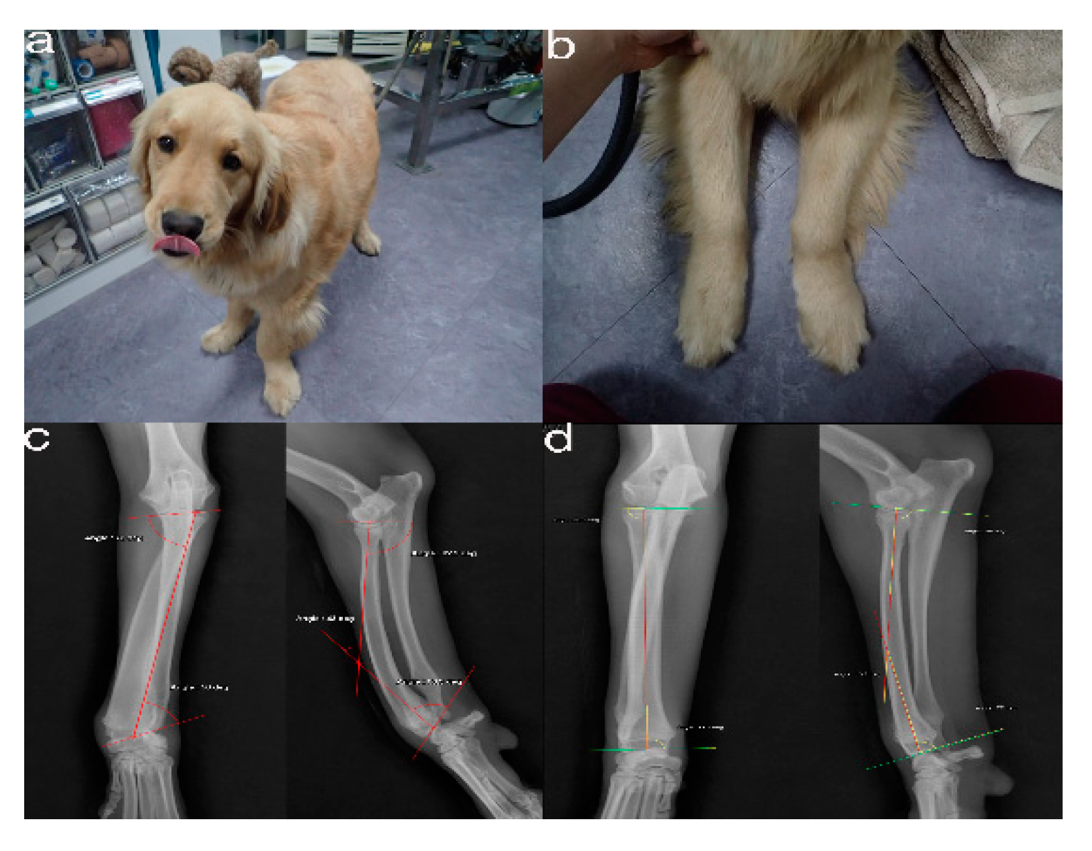
Figure 1. The images show the antebrachial growth deformity (AGD)-affected (left leg) and contralateral unaffected-antebrachium (right leg) with the joint-orientation angles (
. The images show the antebrachial growth deformity (AGD)-affected (left leg) and contralateral unaffected-antebrachium (right leg) with the joint-orientation angles
a,
ab
), and orthogonal radiographs (
b), and orthogonal radiographs
c,
cd
).
d).
Pr o
Figure 2. CT from the distal third of the humerus to the metacarpal bones of both the affected (a) and unaffected leg (b)
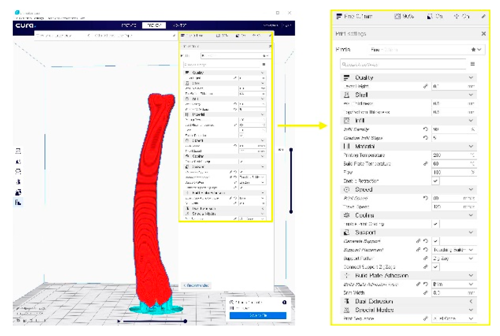
Figure 2 . A G-code file generating process for the 3-D printing process. It can be generated from the STL image using the CURA application program.
. A G-code file generating process for the 3-D printing process. It can be generated from the STL image using the CURA application program
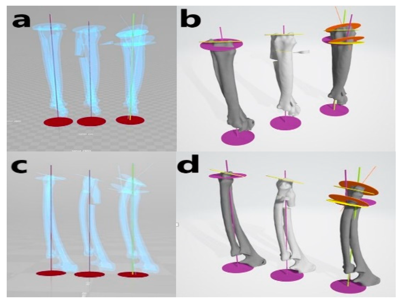
Figure 3 . Virtual simulative corrective osteotomy. Surgical simulations were performed in virtual reality to predict postoperative conditions. Note the change in the axis before and after the virtual corrective osteotomy. The figure on the left (
. Virtual simulative corrective osteotomy. Surgical simulations were performed in virtual reality to predict postoperative conditions. Note the change in the axis before and after the virtual corrective osteotomy. The figure on the left
a,
ac
) shows penetrated images and on the right (
c) shows penetrated images and on the right
b,
bd
) are 3-D rendering images.
d) are 3-D rendering images
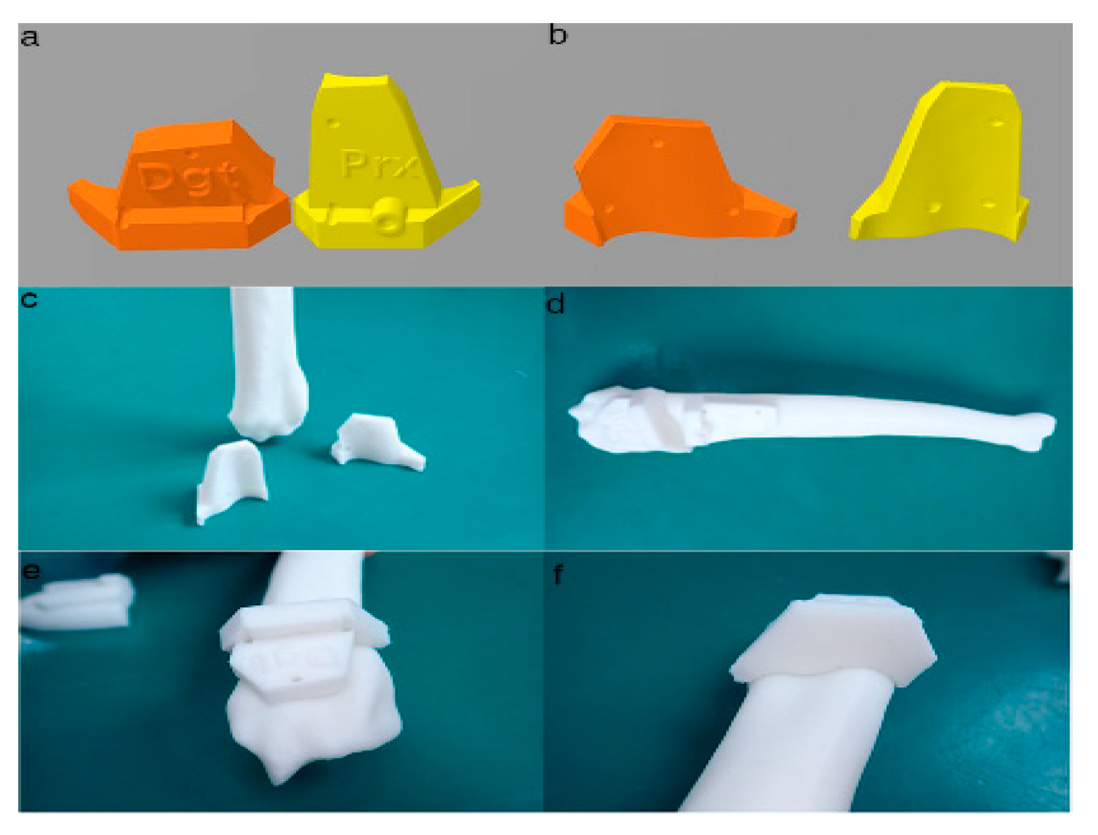
Figure 4 . Final designs of patient-specific instrumentation (PSI) models were demonstrated through 3-D rendering images (
. Final designs of patient-specific instrumentation (PSI) models were demonstrated through 3-D rendering images
a,
ab
), 3-D printed PSIs (
b), 3-D printed PSIs
c), and the PSIs positioning on a rapid prototyping (RP) bone model precisely (
c), and the PSIs positioning on a rapid prototyping (RP) bone model precisely
d–
df
). The patient-specific cutting guides added a drill guide for the bone plate and screw placement. The PSIs attached on the RP bone model in-situ (
f). The patient-specific cutting guides added a drill guide for the bone plate and screw placement. The PSIs attached on the RP bone model in-situ
d–f).
f)

Figure 5 . Rapid prototyping bone models were fabricated with the polylactic acid material using the fused deposition modeling method (above,
. Rapid prototyping bone models were fabricated with the polylactic acid material using the fused deposition modeling method (above,
a,
ab
) and then the phantom bone models were fabricated for this study (below,
b) and then the phantom bone models were fabricated for this study (below,
c).
c)
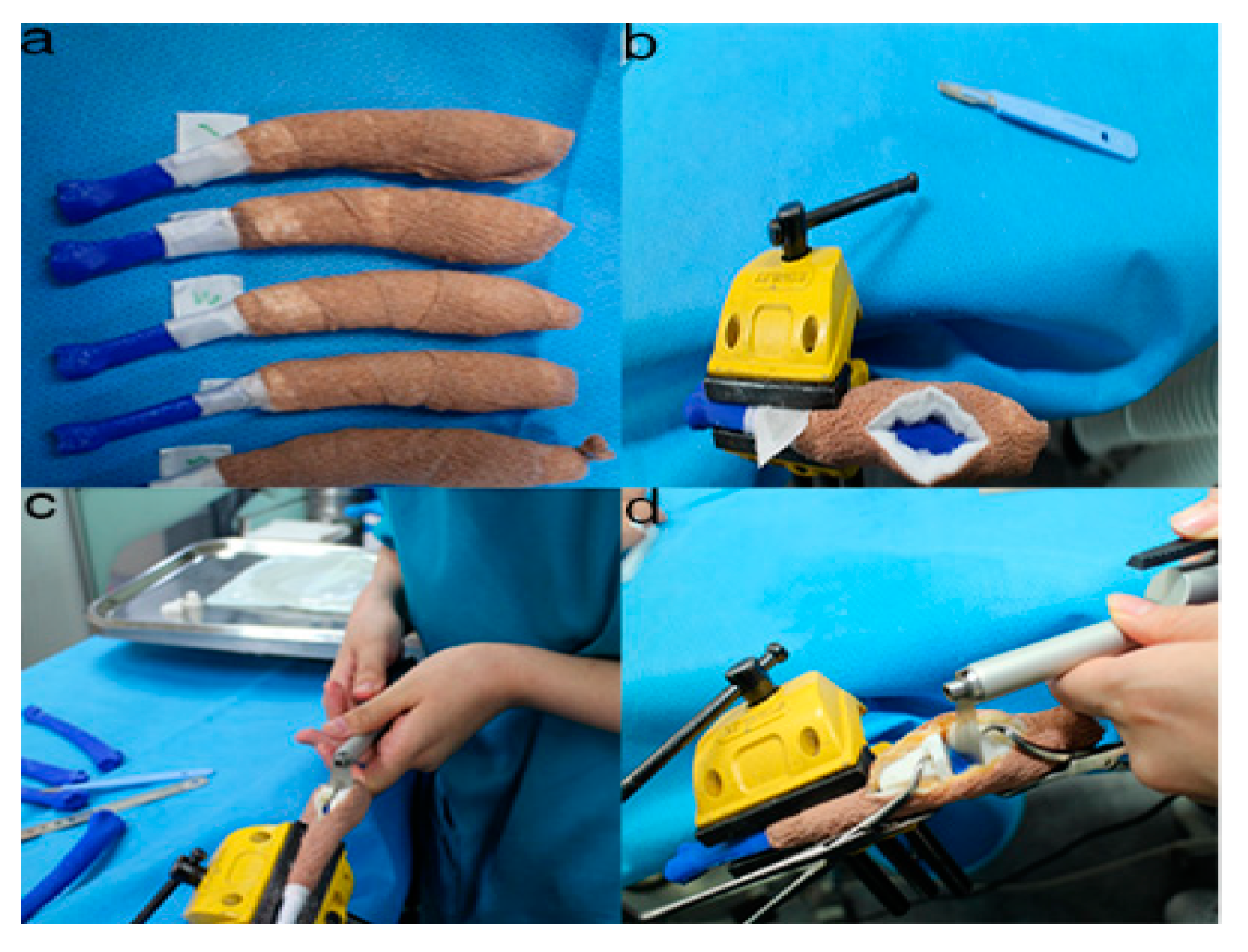
Figure 6 . The position and angles for the cutting procedures. Prior to the ex-vivo osteotomy, each of the five operators were directed to position the phantom bone model to a vise (
. The position and angles for the cutting procedures. Prior to the ex-vivo osteotomy, each of the five operators were directed to position the phantom bone model to a vise
a,
ab
). The surgical planning conditions for the freehand method were the same as the patient-specific instrumentation (PSI) method (
b). The surgical planning conditions for the freehand method were the same as the patient-specific instrumentation (PSI) method
c). Positioning PSI was ordered without positioning aids, but was only fixed on the rapid prototyping model using the bone-holding forceps or K-wires for temporary fixation (
c). Positioning PSI was ordered without positioning aids, but was only fixed on the rapid prototyping model using the bone-holding forceps or K-wires for temporary fixation
d).
d)
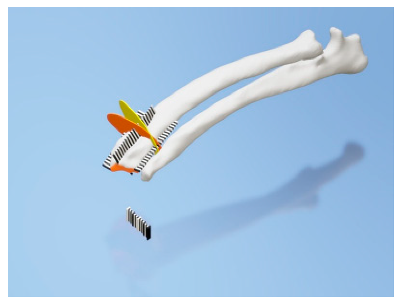
Figure 7 . Rulers were attached to the cranial, caudal, medial, and lateral bone model surfaces. The orange and yellow plates show the osteotomy target plane. The black and white striped bar is made 1 mm against each space to indicate the distance from the edge of the joint surface.
2. Development of Three-Dimensional Bone Phantom
Since over- and under-correction could lead to the loss of restoration of range motion, the accuracy of pre- and post-operative reconstruction is critical[31]. Hence, computerized 3-D comparisons of the contralateral bones are useful for preoperative planning of the corrective osteotomy in the complicated angular deformities and complex malunions. Some technologies, such as navigation systems and PSIs, have assisted surgeons to perform as accurate as planned in human orthopedic medicine [32][33]. In particular, PSIs are becoming more popular because they are easier to handle than navigation systems and are more precise than free hand in vitro study[34].
To compare the traditional CORA measurement orthogonal radiographs with a CT-defined wedge, we utilized radiographs of both models. Fixation of elbow of the model rendered replication of the dog’s limb difficult. Regardless, two methods of measurement yielded significantly different results with terms to the wedge angle and orientation. The use of 3-D CT reconstruction, to identify the true orientation of joint surfaces to apply the CORA approach, has not been previously described in animals.
Meola et al. performed CT scans to assess radial torsion in the presence of procurvatum and valgus deformity in dogs[35]. CT data are being extensively used in human studies[36]. To provide guidance for correction, unaffected opposite 3-D CT data should be collected to serve as reference data. In orthopedic surgery, a similar technique to our method has been described, but instead of estimating a normal for the curvature of the bone from the joint surface, the contralateral limb was used as a guide [37]. However, one of the drawbacks of this technique is that the contralateral limb is also affected by deformity, this method may fail to replicate the normal anatomy.
Fox et al. have described the mean medial proximal radial angle the mean lateral distal radial angle as 85° and of 87°, respectively, in the frontal plane[27]. 4.88° was the calculated mean torsion in the transverse plane in three dogs[35]. However, these data were based on radiographs calculations and have not been determined from CT reconstructions. Additionally, these data were obtained from medium-to-large, non-chondrodystrophic dogs, and as observed, these angles are likely to vary among breed[27]. Studies using 3-D CT to determine the lateral and cranio-caudal planes accurately and the degree of torsion are useful to guide the future computer-assisted surgeries for ALD.
In one study that applied a two-level corrective osteotomy, just 44% of surgical cases were adjusted in both the frontal and sagittal planes [22]. Therefore, the authors pursued a one-level amendment in this case. To perform a single closing wedge osteotomy accurately, we brought a 3-D CT scan, virtual rehearsal surgery with 3-D Builder, a free software into surgical planning protocol. According to our knowledge, the use of this free 3-D design application to simulate a proposed surgery has not been previously published in veterinary surgery. This data was subsequently used to generate a stereolithographic image in plastic which could be handled by the surgeon in rehearsal surgeries and in the operating room. This guaranteed the accuracy of the intra-operative osteotomy as the fragments were aligned to the same angulation as the surgical plan that allowed fixation of plates to be performed precisely.
The study attempted a surgical protocol that was simple to deploy in veterinary surgery and could be run at a low cost. That is why we had to plan a wedge technology with a straight oscillating saw blade rather than choosing to use a radial or domed saw blade. This dog’s highly dynamic character would require an additional orthogonal directional bone plate placement.
This study showed good precision while using the PSI procedure during simulated osteotomy of the radial bone angular deformity. Osteotomy angulation in the distal and proximal plane assessed in articles of the ISO1101 location parameter indicated how PSI is reliable in the operating room to replicate a preoperative cutting plan on a distal radius with clinical accuracy[38].
Our results agree with those of Oka et al. [39], which found average residual errors of simulated osteotomy using patient-specific guides of less than 1° and 1 mm. Investigations using PSI technology had already described promising clinical outcomes. However, their evaluation was only based on intraoperative plane images using image intensifiers. Moreover, the amount of correction and the demographic data of the patients were not exposed.
The presented results revealed that the PSI cutting with regard to the location and surgical angles is quite precise. The data presented in this study could be beneficial for the quantitative comparison of various PSI design processes for bone-cutting within the end of the long bone. The presented results did not suggest any notable difference between experienced and inexperienced surgeons using PSI technology with regard to the location accuracy and cutting angles achieved. It appears that the PSI technology may be ready to use by experienced as well as inexperienced digital-aged surgeons.
Results with regard to the location accuracy showed that PSIs enabled surgeons to repeat preoperative cutting planning with good accuracy (Figure 3, Figure 4 and Figure 5). Otherwise, the value added by the PSI technology in improving bone-cutting accuracy was similar to that of the planned osteotomy target points and planes. The results regarding the obtained surgical margins (Figure 3, Figure 4, Figure 5 and Figure 6) suggest that PSI technology tended to provide a smaller standard deviation than freehand. Otherwise, the manual cutting errors were minimum with the PSI technology compared to those with the freehand method. Further research should be carried out to verify the results observed in this study.
The operation time measured was about 4.8 min bone cutting time during the phantom bone surgery using PSI, similar to the cadaveric long bone resection surgery by Sarah et al.[40]; moreover, compared to the previous report [40]. This study confirmed that PSI technology save time for surgeons compared with other techniques—i.e., in less than 10 min with PSI versus up to 16 min in their study. This can be interpreted by the predefined optimal location of the PSI on the bone surface, which serves as an intuitive and natural transfer of the surgical plan in comparison with the time-consuming manual image-to-patient enrollment phase of the procedure (Figure 3, Figure 4, Figure 5, Figure 6, Figure 7). Given the time-consuming factors—such as the presence of muscles and nerves, bleeding, patient movements, etc.—further in vivo research will be performed to verify the results observed here.
. Rulers were attached to the cranial, caudal, medial, and lateral bone model surfaces. The orange and yellow plates show the osteotomy target plane. The black and white striped bar is made 1 mm against each space to indicate the distance from the edge of the joint surface