Your browser does not fully support modern features. Please upgrade for a smoother experience.
Please note this is a comparison between Version 1 by Leonardo Afonso Vidas and Version 2 by Nora Tang.
Storage is an essential topic when it comes to hydrogen integration in distribution networks and large-scale applications; the existence of a robust and reliable way of storing this energy vector is crucial to addressing the current potential demand for hydrogen in the energy market. Many forms of storage have been developed, which can mainly be divided into Physical-based and Material-based approaches. Physical storage includes compressed gas, liquid, and cryo-compressed hydrogen, and it is the most widely used storage type among these systems.
- hydrogen technologies
- hydrogen economy
- hydrogen storage methods
- natural gas infrastructures
- compressed hydrogen
- liquid hydrogen
- cryo-compressed hydrogen
1. Compressed Gaseous Hydrogen
Compressed hydrogen gas (CGH2), in order to store it, is not a new idea; in fact, in 1880, hydrogen was already stored for military use at pressures of 12 MPa. It was not until the 1960s—when the military and aerospace industries developed high-pressure composite vessels (made of aluminium with a polymer liner and fibreglass wrapping)—that tanks capable of withstanding much higher pressures were developed. In 1970, breathable apparel for firemen was introduced, and in the following decade, pressure vessels were used for the first time in professional diving and in other applications such as recreation paintball. Nowadays, hydrogen storage tanks’ pressures range from 35 MPa to 100 MPa and are already used in fuel cell electric vehicles.
Each differs in the maximum allowable pressure, the materials used, and the overall design as well as in cost (and consequently, in market share). Choosing what type of tank to use is primarily based on the final application, usually requiring a compromise amidst technical performances and cost competitiveness.
Moradi and Groth [1] presented tanks in four different types of pressure vessels, as shown in Figure 1, to be used for hydrogen storage.
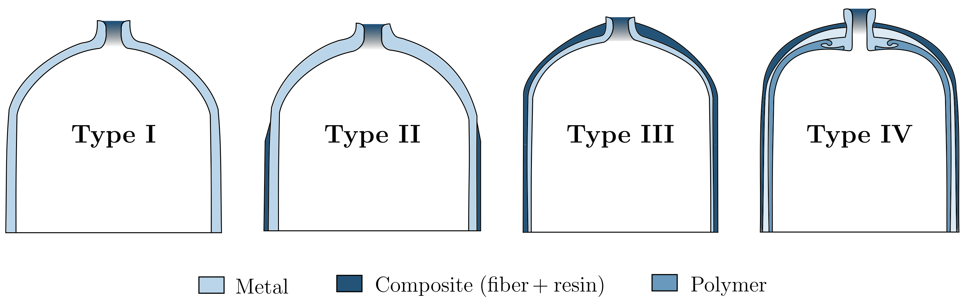
Figure 1. Different types of pressure vessels.
Type I tanks are fully metallic, mainly aluminium or steel, thus being the cheapest—and hence the most used for industrial hydrogen storage; it is also the heaviest (about 1.50 kg per litre of hydrogen), and pressures inside can reach up to 50 MPa. Type II vessels are made of thinner steel walls but have a fiberglass composite over-wrap—ensuring one of the highest pressure tolerances and allowing a reduction of about 40% in weight when compared to Type I tanks. Its design provides a structural load distribution, equally divided between the steel and the composite parts, which also leads to a 50% increase in the manufacturing price; it is mainly used for stationary applications. Type III and Type IV vessels are planned for mobile applications, in which weight performance is essentially optimized; however, they are much more expensive. Type III are full composite-wrap tanks with just a metal liner for sealing purposes; the structural load is mainly carried by the carbon fibre composite and can safely withstand maximum pressures of around 45 MPa. This type of vessel has much better weight performance than the previous ones, weighing only about 0.40 kg per litre of hydrogen (but at double the cost). Finally, Type IV vessels usually have a high-density polyethylene plastic for the liner and a carbon-fibre/carbon-glass material for the structure. This vessel can hold pressures as high as 100 MPa while being the lightest among all four types—but it is also the most expensive.
M. Legault [2][9] wrote about an additional fifth stage, which has been studied for more than a decade now and aims to be a true fully composite pressure vessel. Composites Technology Development, Inc. (Lafayette, Colorado, USA) has successfully designed, tested, and built such a tank for a real-world application, with its main advantage being its extremely low weight: it is 20% lighter than a Type IV tank. However, as Barthelemy et al. [3][8] stated, since its operational pressure is only 1.37 MPa, it is deemed unsuitable to withstand current pressures needed to store enough amounts of hydrogen outside of a laboratory.
As mentioned above, the design of such vessels must take into account several aspects, including service pressure, the external mechanical stresses or impacts they are subjected to, their lifecycle and lifetime, and their safety coefficient requirements for both static and dynamic situations. In general, all metallic parts are usually made of aluminium 6061/7060 or steel inox, and all polymer parts mainly make use of polyethylene or polyamide-based materials. The composites’ components are commonly a mix of glass, aramid, or carbon fibre and a resin, which can be polyester, phenol, or epoxy (the latter being preferred for its greater mechanical properties and stability) [3][8].
2. Liquid Hydrogen
Although liquid hydrogen (LH2) storage has not been around as long as compressed hydrogen tanks have, it has existed for some time now; cryogenic tanks were first used about 50 years ago in the industrial and medical gas-transportation businesses, and they are fully adopted and commercially accessible today.
To obtain hydrogen in liquid form, it must first be cooled to below −253 °C, a process that usually requires both a lot of time and great amounts of energy—more precisely, as Moradi and Groth [1][7] elaborated, up to 40% of the energy content of the same hydrogen being cooled (as opposed to just 10% when it is compressed). Even so, cryogenic hydrogen storage under atmospheric conditions presents a larger energy density than when it is compressed (almost triple when at 35 MPa, as identified by A. Fradkov [4][10]) and therefore has better storage efficiency; this is why traditionally, liquid hydrogen has been preferred for space programs [5][11], aircraft flights [6][12], and intercontinental storage shipping [7][13], among others. However, due to its very low boiling temperature, hydrogen becomes problematic to store cryogenically for long periods of time, which puts it at risk of yield loss by natural evaporation; Barthelemy and his co-authors [3][8] asserted that this explains why it is not a favourable solution for on-board vehicle storage. However, it is the favoured form for medium-/large-scale truck delivery and long-range international transport [8][14]; a cryogenic vessel can carry around 5000 kg of liquid hydrogen, five times the nominal capacity of current hydrogen gaseous pipe trailers [1][7], without the associated risks [9][15].
Current designs of liquid hydrogen tanks need to consider three primary parameters: shape, volume, and insulation.
The shape of the tank depends on a few elements, mainly the materials to be used, the space available for the tank, and the stresses it will be subjected to. As in the storage of many other liquids, Allideris and Janin [10][16] found that spherical or cylindrical shapes are also preferred for the storage of LH2, since there is better load distribution and avoidance of stress concentration at the corners of the typical quadrangular tanks. For any given volume, the sphere is known to be the geometrical object with the least surface area; thus, the passive heat flux with the exterior is reduced and the boil-off rate is lowest, as pointed out by Mital et al. [11][17]. However, spherical tanks are hard to manufacture, have a large frontal surface, and are not particularly good at tessellating space (that is, they do not stack well). On the other hand, as G. Brewer [12][18] cleverly explained, cylindrical-shaped tanks are much easier to fabricate and, while they may have the same frontal surface, they stack much better, thus yielding higher volumetric storage efficiencies and optimal storing configurations. The major drawbacks of cylindrical-shaped vessels are the larger area-to-volume ratio (which result in a higher passive heat flux) and the uneven distribution of pressure close to the bases. To deal with this issue, Khandelwal and his co-authors [6][12] proposed turning the ends of the cylinder into hemispherical caps; such spherocylinder is considered to be the standard shape for tanks nowadays as it puts together the best features of both geometries.
The shape of the tank depends on a few elements, mainly the materials to be used, the space available for the tank, and the stresses it will be subjected to. As in the storage of many other liquids, Allideris and Janin [10][16] found that spherical or cylindrical shapes are also preferred for the storage of LH2, since there is better load distribution and avoidance of stress concentration at the corners of the typical quadrangular tanks. For any given volume, the sphere is known to be the geometrical object with the least surface area; thus, the passive heat flux with the exterior is reduced and the boil-off rate is lowest, as pointed out by Mital et al. [11][17]. However, spherical tanks are hard to manufacture, have a large frontal surface, and are not particularly good at tessellating space (that is, they do not stack well). On the other hand, as G. Brewer [12][18] cleverly explained, cylindrical-shaped tanks are much easier to fabricate and, while they may have the same frontal surface, they stack much better, thus yielding higher volumetric storage efficiencies and optimal storing configurations. The major drawbacks of cylindrical-shaped vessels are the larger area-to-volume ratio (which result in a higher passive heat flux) and the uneven distribution of pressure close to the bases. To deal with this issue, Khandelwal and his co-authors [6][12] proposed turning the ends of the cylinder into hemispherical caps; such spherocylinder is considered to be the standard shape for tanks nowadays as it puts together the best features of both geometries.
Regarding volume, this is usually set according to the required mass. Therefore, once the mass of liquid hydrogen needed has been defined, the volume of the tank is then determined by the following equation (with V representing the volume of a capsule, r the radius (accounting for both hemispheres) and l the length of the cylindrical part).

Hence, the tank’s shape parameters have to be chosen in accordance with the mass of the LH2 required to be carried, its nominal temperature, the operating pressure of the vessel, and the insulation thickness [13][19]. At the time of its design, a trade-off has to be considered between the volume of the tank and the space available on the carrier.
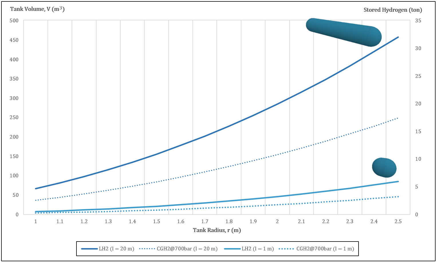
Figure 2. Relation between radius, volume, and stored mass of a typical hydrogen capsule-shaped tank.
Figure 2 sThows the tank volume (on the left vertical axis) and the stored hydrogen mass (on the right vertical axis) as functions of the tank radius; the lightlight-blue solid line refers to a spherocylinder with a length of just one meter, while the dark blue solid line represents a tank 20 m in length. The round-dotted lines indicate the performance of similar tanks with compressed gaseous hydrogen inside, at a pressure of 70 MPa. The increase in density with the transition from the gaseous to the liquid state is very clear here; a capsule tank 20 m in length can transport twice the mass of hydrogen if it is liquid instead of gaseous. Note that the dimensions shown here are of the interior vessel; nowadays’ cryogenic trailers may have these dimensions for the exterior tank, thus having much smaller interior capsules than the ones shown in this graph.
Understanding the differences in size between the interior vessel and the exterior tank is understanding insulation; the storage of hydrogen at such low temperatures requires special high-efficiency insulated tanks. This can be achieved by applying internal and/or external insulation. Internal insulation is always hard to implement since the materials are in direct contact with hydrogen in cryogenic temperatures; heat transfer phenomena cause the transition of hydrogen from a liquid state to a gas state at these contact boundaries, diffusing gaseous H2 into the walls of the tank. This then increases the thermal conductivity of the insulation material, thus damaging its efficacy [6][12]. Therefore, the system would have to be impermeable to CGH2 [12][18].
In the case of external insulation, the problem is not so much the direct contact with extremely low temperatures, but rather the contractions and expansions that the materials undergo, which come respectively from the charge and discharge of liquid hydrogen at these temperatures. Moreover, there is also an attachment issue for the support systems as well as possible mechanical damage from impact loads [12][18]. Nonetheless, these problems are more easily solved than those of internal insulation. Hence, the main challenge involving liquid hydrogen storage is the boil-off phenomenon; as previously explained, this occurs when heat is transferred to the tank’s interior, consequently warming the liquid hydrogen and effectively turning it into a gas (depending on several factors, up to 1 wt% per day due to heat in-leakages from the environment alone, as disclosed by Sherif et al. and confirmed by C. Yang and J. Ogden. [14][15][21,22]). Boil-off management is then an extremely relevant matter with regard to cryogenic hydrogen storage since it can lead to an unwanted pressure increase inside the rigid vessel; once the nominal maximum pressure is reached, the boil-off valve opens and ventilates part of the gas to the exterior. To reduce this effect—and thus reduce energy losses—several solutions have been adopted: Notardonato et al. [16][23] proposed an integration of cryo-coolers in the frame, while J. Wiley [17][24] recommended a storage combination with the chemical metal hydrides; Ho and Rahman favoured a cooling combination with liquid nitrogen (which is used to 'shield' the insulated tank, hence drastically reducing the heat transfer to the environment) and the installation of passive insulation [18][25]. This last solution can branch into several techniques, as pointed out by A. Züttel and J. Reijerkerk [19][20][26,27], with the use of vacuum, foam, and multi-layer insulation:
In the case of external insulation, the problem is not so much the direct contact with extremely low temperatures, but rather the contractions and expansions that the materials undergo, which come respectively from the charge and discharge of liquid hydrogen at these temperatures. Moreover, there is also an attachment issue for the support systems as well as possible mechanical damage from impact loads [12][18]. Nonetheless, these problems are more easily solved than those of internal insulation. Hence, the main challenge involving liquid hydrogen storage is the boil-off phenomenon; as previously explained, this occurs when heat is transferred to the tank’s interior, consequently warming the liquid hydrogen and effectively turning it into a gas (depending on several factors, up to 1 wt% per day due to heat in-leakages from the environment alone, as disclosed by Sherif et al. and confirmed by C. Yang and J. Ogden. [14][15][21,22]). Boil-off management is then an extremely relevant matter with regard to cryogenic hydrogen storage since it can lead to an unwanted pressure increase inside the rigid vessel; once the nominal maximum pressure is reached, the boil-off valve opens and ventilates part of the gas to the exterior. To reduce this effect—and thus reduce energy losses—several solutions have been adopted: Notardonato et al. [16][23] proposed an integration of cryo-coolers in the frame, while J. Wiley [17][24] recommended a storage combination with the chemical metal hydrides; Ho and Rahman favoured a cooling combination with liquid nitrogen (which is used to 'shield' the insulated tank, hence drastically reducing the heat transfer to the environment) and the installation of passive insulation [18][25]. This last solution can branch into several techniques, as pointed out by A. Züttel and J. Reijerkerk [19][20][26,27], with the use of vacuum, foam, and multi-layer insulation:
-
Vacuum insulation. While a perfect vacuum may seem to be the best solution to eliminate the boil-off effect, it is also extremely difficult to achieve; as demonstrated by A. Colozza [21][28], peripheral equipment and venting devices are required to actively maintain the vacuum region. A vacuum chamber also raises issues about the thickness of the tank walls—they must be wide enough to withstand the buckling effect caused by external ambient pressure; however, as Millis et al. [22][29] reiterated, large walls in conjunction with additional stiffeners (required in-between the vacuum jacket shell) will inevitably increase the overall weight of the tank.
-
Foam insulation. Despite not having insulation levels as good as those of vacuum chambers, foam insulation is a passive technique, easier and cheaper to implement. Usually, these foams are very light, have low density, and have low thermal conductivity; in his PhD thesis, I. Cumalioglu [23][30] studied how these are applied, sandwiched between two metal plaques, in order to improve structural stability and to better protect against external forces and impacts. Another great advantage of foam insulation over vacuum-jacketed insulation is its resistance to catastrophic failure; a pierced vacuum chamber would probably cause the overall collapse of the insulation layer, whereas foam insulation would not [19][26].
-
Multi-layer insulation. This method can be seen more as a compliment to the previous two rather than as an alternative—although it is also possible to implement it as a stand-alone. Multi-layer insulation systems are commonly a set of reflective foil made of thermal radiation shields aligned perpendicularly to the direction of the heat flux; they are usually wrapped over the external layer of the tank in order to impede radiation heat transfer. These radiation shields mostly consist of alternate layers of thin aluminum foil and an insulating material such as fiberglass or polyester [3][8]. While additional layers may improve insulation from heat radiation, it also increases heat transfer by conduction; to cite Khandelwal and his co-authors [6][12], the optimal recommended number of layers is then between 60 and 100. Naturally, more layers will also add to the overall weight of the tank. Another drawback of multi-layer insulation sheets is their sensitivity to pressure gradients during manufacturing, as studied by Allideris and Janin [10][16]; this leads to the need for a very specialized type of production, which is more expensive. Further attention needs to be given to damage use accumulation resultant from external loads such as impacts during operation or unpredictable accidents, which can lead to fibre breaks, delamination, and matrix cracking [3][8].
As was notably mentioned by Kamiya and his co-authors [24][31], while heat inputs may be minimized through the use of the above-mentioned insulation techniques, sloshing is not. Sloshing occurs mainly during the acceleration/deceleration periods of trailer transport, where heat may be generated by the inherent vibration of the tanks; this can be overcome with the introduction of slosh-baffles—a device that dampens the adverse effects of sloshing and also increases the natural frequency of the tank [14][21].
Having seen the various methods of preferred exterior insulation, what happens in the interior of such tanks remains to be analyzed. An important matter to consider here is the material compatibility between hydrogen and the substance with which the vessel is made; the inner part of these vessels is usually made of stretched stainless steel. However, this raises concerns about the possible effects of hydrogen embrittlement, where hydrogen atoms diffuse into the structure of the metal [25][32]; by accumulating at locations with higher cracking potential, severe changes to the metal’s mechanical properties may happen—mainly a decrease in ductility, toughness, and load-bearing capability. At the same time, it also increases hardness and thus the propensity for premature brittle fractures. Note that this effect can happen with hydrogen in both the gaseous and the liquid states, and that this issue can have even greater impact when considering multi-material assemblies (as is the case with both compressed and cryogenic vessels). Among the methods for minimizing hydrogen embrittlement, Li et al. [26][33] indicated the use of special inner-surface treatments involving coating and surface material modifications as one of the most conventional approaches.
Regarding safety issues, Petipas and Aceves [27][34] believed that any explosion scenario is very unlikely to happen, since hydrogen has a low adiabatic expansion energy at very low temperatures; however, potential leakages can effectively damage nearby valves and devices that have not been rated to withstand such low temperatures, thus causing further malfunctioning.
Usually, liquid hydrogen stored at ambient temperature is pumped through vacuum insulated piping to reach pressures of up to 85 MPa and densities as high as 85 g/L; an evaporator stage then converts it into a super-cooled gas before it is stored in special, carbon fibre-wrapped, metal, cryo-compressed vessels (similar to those of Type III for CGH2) [31][38]. Moreno-Blanco and his co-authors [32][39] found that storage density can be higher this way since liquid hydrogen is slightly more compressible: at −252 °C, it is 87 g/L at 240 bar compared to 70 g/L at atmospheric pressure.
Regarding safety issues, Petipas and Aceves [27][34] believed that any explosion scenario is very unlikely to happen, since hydrogen has a low adiabatic expansion energy at very low temperatures; however, potential leakages can effectively damage nearby valves and devices that have not been rated to withstand such low temperatures, thus causing further malfunctioning.
3. Cryo-Compressed Hydrogen
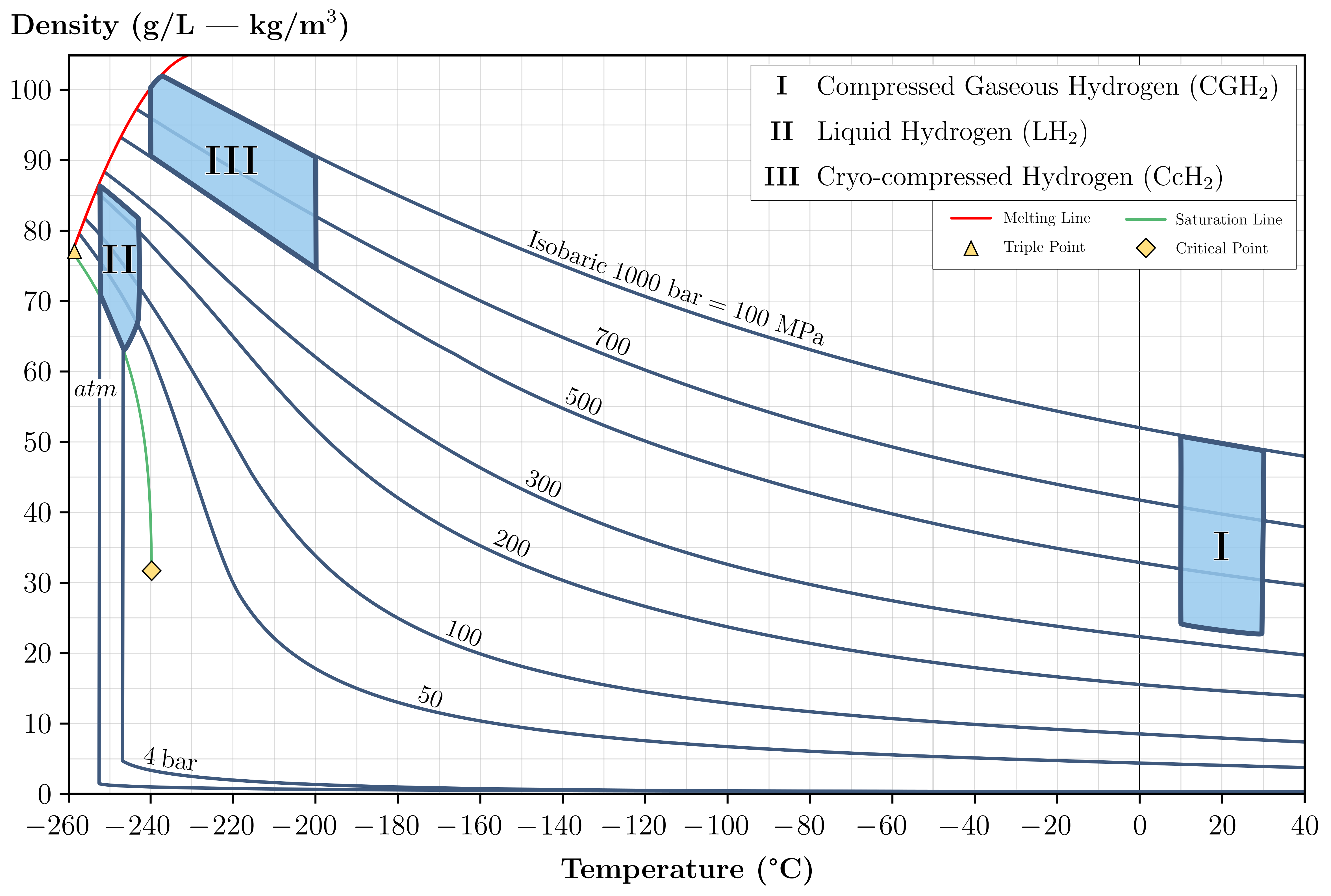
Cryo-compressed hydrogen (CcH2) storage was introduced to overcome the disadvantages of both traditional storage methods mentioned above by combining their main characteristics, as explained by El-Eskandarany and Aceves et al. [28][29][35,36]. This storage occurs at cryogenic temperatures (not as low as with LH2) on a pressurized vessel, although not as much as with CGH2; it can comprise cold compressed hydrogen or hydrogen in a two-phase region (saturated liquid and vapor) [30][37]. Figure 3 illustrates hydrogen density as function of temperature and pressure, displaying the different storage methods discussed so far.
Figure 3. Correlation of hydrogen density and temperature for different conditions.
Usually, liquid hydrogen stored at ambient temperature is pumped through vacuum insulated piping to reach pressures of up to 85 MPa and densities as high as 85 g/L; an evaporator stage then converts it into a super-cooled gas before it is stored in special, carbon fibre-wrapped, metal, cryo-compressed vessels (similar to those of Type III for CGH2) [31][38]. Moreno-Blanco and his co-authors [32][39] found that storage density can be higher this way since liquid hydrogen is slightly more compressible: at −252 °C, it is 87 g/L at 240 bar compared to 70 g/L at atmospheric pressure.
Cryo-compressed hydrogen storage presents some advantages when compared to traditional methods, such as an overall higher energy density, volumetric efficiency and gravimetric capacities [31][38], a reduced boil-off effect [33][40], and thus reduced in-vessel over-pressurization and longer thermal endurance [34][41], among others. Stetson et al. [35][42] also demonstrated how cryo-compressed storage tanks are one of the most versatile since they are designed to endure both very low temperatures and very high pressures. However, there are still some limitations preventing this technology from becoming commercially viable; cryo systems are generally very complex and hard to implement, requiring the permanent and careful management and monitoring of their thermal insulation levels [31][38] as they have considerable maintenance costs, high energy needs for operation, and a short no-loss unused period [36][43].
Recently, numerous advancements have been made with respect to the geometry and the materials of the tanks used in these systems, since their performance highly depends on these aspects; thus far, an effort to compress the whole system was made, resulting in the halving of the vessel’s coating thickness to 1.5 cm. Nevertheless, Sdanghi et al. [31][38] emphasized that particular research should be carried out concerning the use of alloys of lighter density as coating materials.
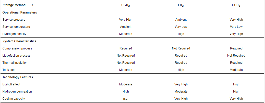
The Table 1 following summary table displays the main attributes of the three physical ways of storing hydrogen discussed.
Table 1. Major features of physical hydrogen storage technologies.
| Storage Method ⟶ | CGH2 | LH2 | CCH2 |
|---|---|---|---|
| Operational Parameters | |||
| Service pressure | Very High | Ambient | Very High |
| Service temperature | Ambient | Very Low | Very Low |
| Hydrogen density | Moderate | High | Very High |
| System Characteristics | |||
| Compression process | Required | Not Required | Required |
| Liquefaction process | Not Required | Required | Not Required |
| Thermal insulation | Not Required | Required | Required |
| Tank cost | Moderate | High | Moderate |
| Technology Features | |||
| Boil-off effect | Moderate | Very High | High |
| Hydrogen permeation | High | Moderate | High |
| Cooling capacity | n.a. | Very High | Very High |
CGH2: Compressed Gaseous Hydrogen; LH2: Liquid Hydrogen; CCH2: Cryo-compressed Hydrogen.