Your browser does not fully support modern features. Please upgrade for a smoother experience.
Please note this is a comparison between Version 2 by Dean Liu and Version 1 by Yizhe Guo.
Electrospun nanofibers have become the most promising building blocks for future high-performance electronic devices because of the advantages of larger specific surface area, higher porosity, more flexibility, and stronger mechanical strength over conventional film-based materials.
- electrospinning
- one-dimensional materials
- polymer nanofibers
- metal oxide semiconductor
- organic field-effect transistor
- resistive random-access memory
1. Introduction
One-dimensional (1D) nanostructures have attracted growing interest in the past few decades due to their fascinating properties and unique applications in areas ranging from physics, chemistry, biology, and material science [1][2][3][4][5]. Among different kinds of preparation methods for 1D materials, such as arc discharge, chemical vapor deposition (CVD), laser sputtering, and liquid-phase synthesis, the electrospinning method has been a standout for its simplicity and cost-effective characteristics for producing nanofibers. Currently, hundreds of polymers, inorganic compounds, and composites with one-dimensional nanostructures have been successfully developed based on electrospun materials. With the continuous research, it is believed that more and more types of 1D nanomaterials will be fabricated by the electrospinning method, which will play an increasingly important role in the field of science and technology shortly.
Electrospinning evolves from electrospray technology, and the key technique of electrospray is to destroy the equilibrium of the droplet: the electric field force must be increased to exceed the droplet surface tension so that the bigger droplet will split into smaller charged droplets, which is also known as “Rayleigh instability” phenomenon [6]. Based on this principle, electrospinning produces nanofibers by volatilization or solidification of the jet stream. Because of high aspect ratio, high specific surface area, and porosity of obtained nanofibers, together with effective control of the fiber arrangement and size, electrospinning would have great prospects for applications in electronic devices, energy storage, and biomedicine..
2. Different Types of Electrospun Nanofiber Process and Structures
As one of the most convenient and efficient ways to prepare nanofiber in today’s scientific research, the electrospinning technique emerged in the experiment of German scientist Anton Formhals in the 1930s, and it was originally used to prepare artificial silk-like fibers [7]. This ancient nanotechnology has been rediscovered for modern demands by Reneker’s group, who officially introduced the professional term “electrospinning” in the 1990s [8]. Today, blowout research has made this technique one of the most important methods for the multi-functional, large-scale, and low-cost preparation of continuous nanofibers with diameters as small as nanometers. Generally, the composition of this technology is very simple, mainly including a high-voltage power source, a syringe pump, a spinneret, and a conductive collector (Figure 1) [9]. In the electrospinning process, the droplets ejected by the spinneret generate jets, which are then stretched into nanofibers with the help of the electric field and deposited on the collector. These systems can be easily assembled to realize a spinning system in any laboratory. Electrospun nanofibers have a cross-linked ultra-fine fiber structure, which gives the material the characteristics of large specific surface area, light weight, high porosity, excellent thermal stability, and mechanical flexibility [10][11][12][13]. They have broad applications in filtration membranes, catalytic supports, energy storage, biomedical research, and photonic and electronic devices [14][15][16][17][18][19][20][21][22][23][24]. At present, the applications of electrospinning have not only been studied in the laboratory, but have also made some achievements in the field of commercialization. The first commercial product based on electrospun nanofibers, namely the air filtration technology Ultra-Web®, appeared in 1981 with the work of the Donaldson company [25]. Recently, the international market for electrospun fiber-based applications has been brisk, and the total value reached 927 million dollars in 2018 [26]. It is believed that in the future, the 1D nanomaterials prepared by electrospinning will continue to be developed and this will give full play to their potential to be used in various industries.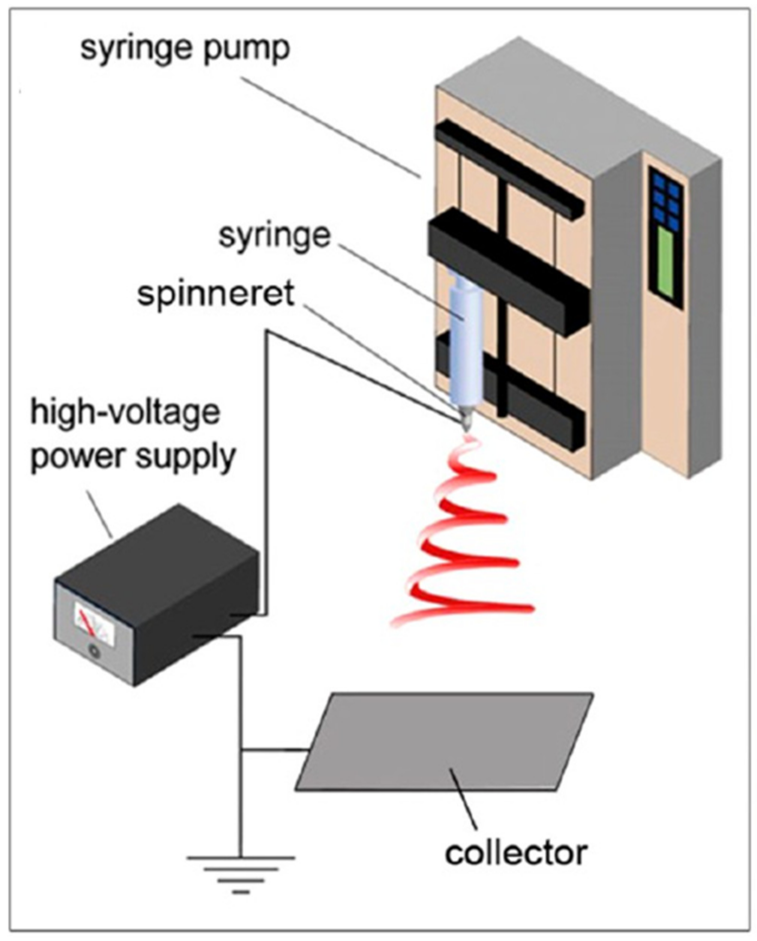
Figure 1.
Schematic setup image for electrospinning method. Reprinted with permission from Reference
[9]
. Copyright 2017 American Chemical Society.
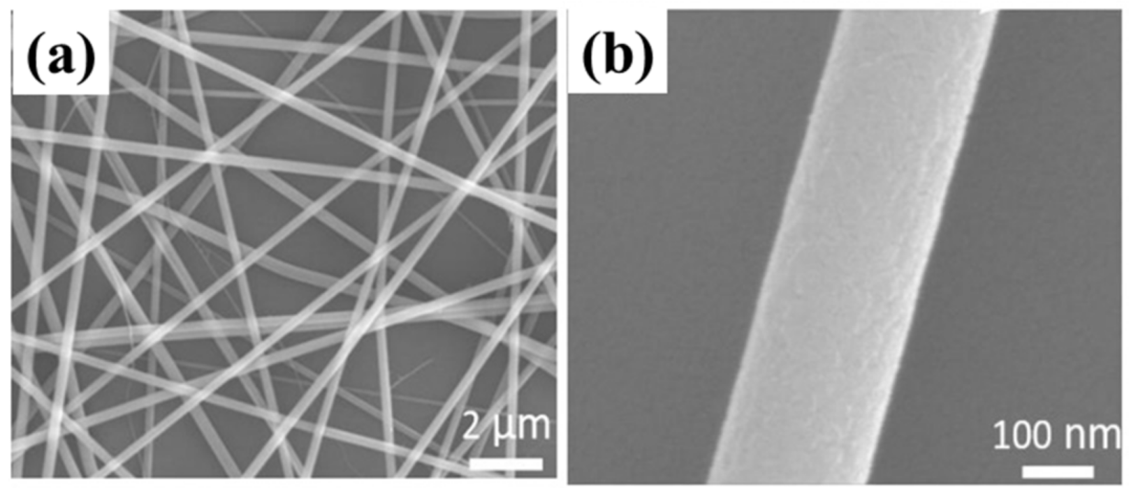
Figure 2. SEM images of as-spun composite InTiO nanowires at different scales: (a) 2 μm, (b) 100 nm. Reprinted with permission from Reference [32]. Copyright 2019 IOP Publishing Ltd.
2.1. Porous Nanofibers by Pretreatment
Nanofibers prepared by traditional electrospinning methods ought to have a solid structure, but porous fibers can have more advantages due to the dramatically increased specific surface area ratio of the material. In the previous study, there were several ways to generate porous nanofibers. First of all, different material concentrations in the solution can easily affect the morphology and pore formation of nanofibers. It has been proven that varying weight percentages of zeolitic imidazolate framework-8 (ZIF-8) can effectively manipulate the formation of pores in the poly (lactic acid) (PLA)/ZIF-8 nanofibers. Increasing concentrations of ZIF-8 (0, 1, 2, 3, 5 wt% based on the weight of PLA) were added to the precursor solution to produce porous fibers with rising pore size from 0.018 μm2 to 0.080 μm2 as exhibited in Figure 3a–e [33]. Besides, selectively removing one of the components from the as-spun fibers is another way to the formation of the porous structure. The calcination process in the fabrication of nanofibers will result in the removal of the organic components. When adding a highly volatile solvent into the spinning solution, pores would appear on the surface of nanofibers after the annealing process. This proper treatment of selective removal of the sacrificial components in the fiber is considered to be the most straightforward approach to generating nanofibers with pores, and several experiments have clarified the contributions of the solvent with volatility such as dichloromethane (DCM) to the porous nanofibers [9]. Finally, electrospinning the nanofibers directly into a cryogenic liquid causes polymer solvent phase separation, providing another route for porous structure formation. Polystyrene (PS), Poly (acrylonitrile) (PAN), and Poly (vinylidene fluoride) (PVDF) nanofibers with pores made by rapidly cooling the fibers before complete solidification can be seen in Figure 4f–h [34].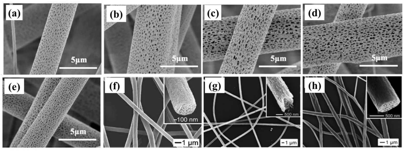
Figure 3. SEM images of The SEM of PLA/ZIF-8 porous fibers with varied ZIF-8 weight percentage: (a) 0, (b) 1 wt%, (c) 2 wt%, (d) 3 wt%, and (e) 5 wt%. Reprinted with permission from Reference [33]. Copyright 2018 Elsevier B.V. (f) SEM image of PS porous electrospun nanofibers (g) PAN fibers electrospun into liquid nitrogen from DMF. (h) PVDF fibers electrospun into liquid nitrogen followed by drying in vacuo. The inset of (f–h) gives an SEM image of the broken end of the fiber at a higher magnification, indicating the fiber is porous throughout. Reprinted with permission from Reference [34]. Copyright 2006 American Chemical Society.
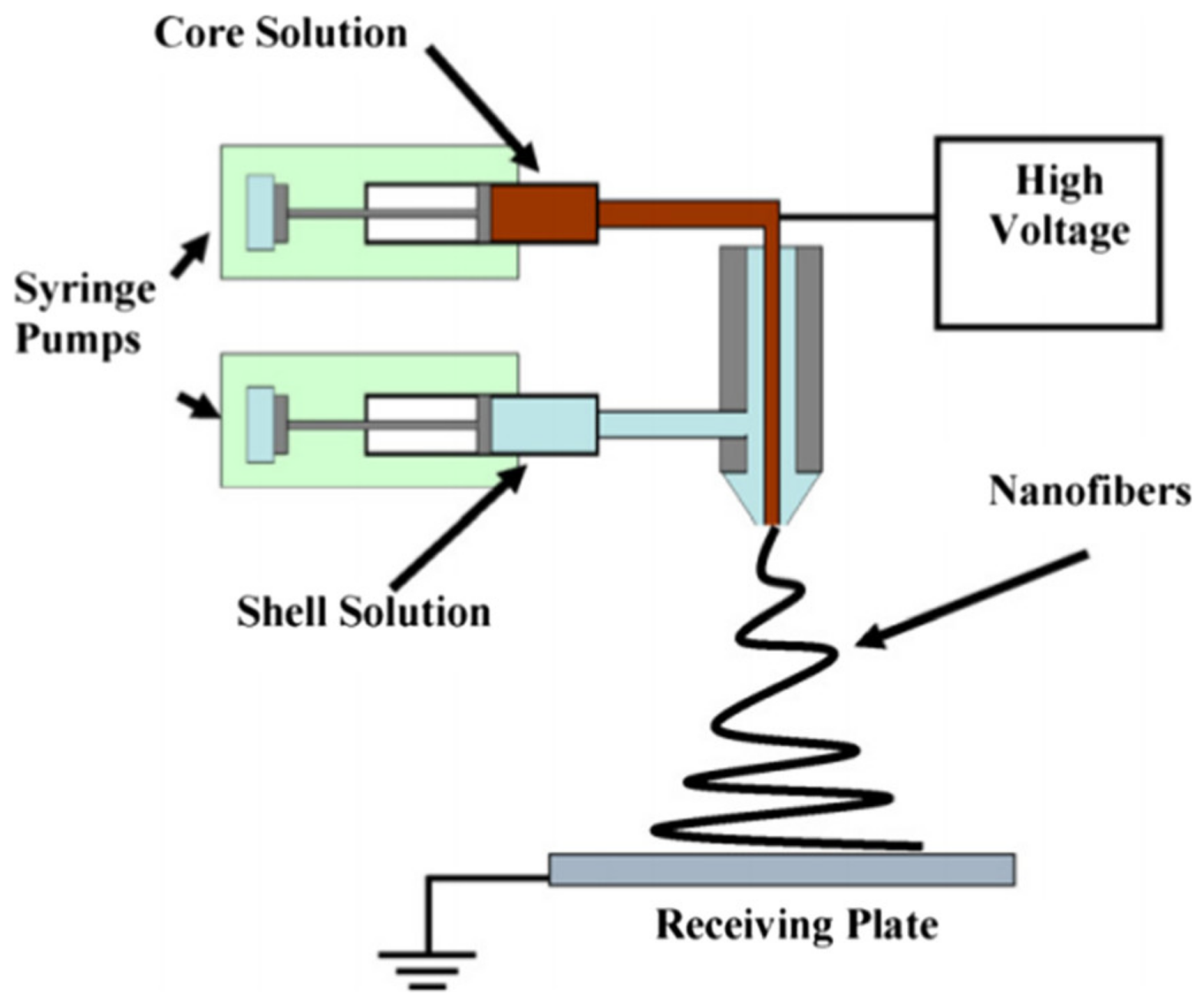
Figure 4.
Schematic diagram of a set-up for coaxial electrospinning Reprinted with permission from Reference
[35]
. Copyright 2010 Elsevier B.V. All rights reserved.
2.2. Hollow Nanofibers by Coaxial Spinneret
The special core-shell structure of electrospun nanofibers can bring high conductivity of several orders magnitude higher than those of common solid nanofibers [36]. Hence, a novel technique of coaxial electrospinning has attracted more attention for fabricating continuous core-shell composite nanofibers or further hollow nanofibers. As shown in Figure 4, the key component of the coaxial electrospinning system is the coaxial needle, with one smaller capillary inside and another larger one in coaxial geometry [35]. These two capillaries separately drive different fluids with tunable flow rates. By pumping both inner and outer precursor solution in the two needles, a compound Taylor cone consisting of the core fluid wrapped by the shell fluid would emerge at the end of the tip to generate continuous core-sheath nanofibers on the receiving plate. In this process, adjustable factors, including the physical properties of both inner and outer materials, as well as electrospinning parameters, altogether play important roles in successfully preparing nanofibers of coaxial morphology. Specifically, the immiscibility of the two electrospun solutions ensures the detached structure of the core and shell fiber instead of mixing or inversion. Sufficient viscosity is another solution factor influencing the production of long and continuous fibers. Moreover, two optimal flow rates of the coaxial fluids should be obtained to keep the inner fluid fully wrapped by the outer one. Different kinds of materials, such as metal salts, eupolymers, and oligomers, have been made in pairs to realize the core-shell structure nanofibers [37][38][39][40]. Figure 5a shows a regular polymer nanofiber blend of poly (vinylidene fluoride) (PVDF) and polyaniline (PANI), and the production of the core-shell nanofibers is also observed by transmission electron microscopy in Figure 5b. Experiment results have proven that a core-shell electrospun fibrous mat had much better conductivity of 2.75 × 10⁻⁹ S cm−1 than 4.08 × 10⁻¹⁴ S cm−1 conductivity for a simple electrospun fibrous mat [41]. Notably, coaxial electrospinning is of great help to produce nanofibers by unspinnable liquids in that these liquids serve as the inner fluid while the outer fluid guides it to spin. For instance, ultrafine Polydimethylsiloxane (PDMS) fibers were prepared by the coaxial electrospinning method using a PDMS and polyvinylpyrrolidone (PVP) as core and sheath materials with the final removal of PVP [42] (Figure 5c–f). Based on core-shell nanofibers, hollow nanofibers can be achieved by the removal of the core materials. In a classic instance, PVP hollow nanofibers derived from PVP/mineral oil core-shell fibers were obtained by being immersed in hexane for 24 h to remove the mineral oil and the hollow structure of these electrospun fibers could be seen in Figure 5g,h [43]. Besides, more complex structures could be constructed in this way with the aid of more spin needles. In one study, multichannel tubes were created by three spinnerets in the layout of an equilateral triangle [44] (Figure 6). A mixture of PVP and Ti(OiPr)4 was added to the outer spinneret while the paraffin oil was fed into the inner three needles. The specific three-channel structure of hollow nanofibers was supposed to form after removing the core oil of the core-shell nanofibers by calcination.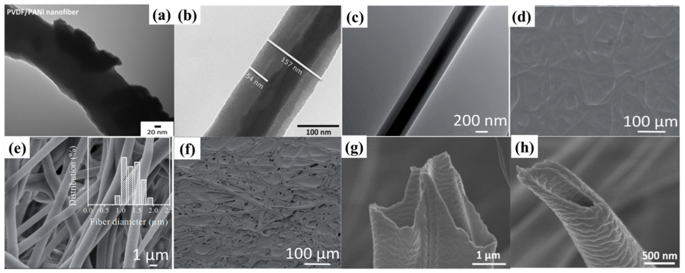
Figure 5. (a) TEM image of PVDF/PANi solid nanofibers. (b) TEM image of PVDF/PVDF-PANI core-shell nanofibers. Reprinted with permission from Reference [41]. Copyright 2013 Society of Plastics Engineers. (c) TEM image of a single PDMS/PVP fiber. (d) SEM image of PDMS/PVP fibers produced at room temperature. (e) SEM image of PDMS fibers collected with PVP component removed (the inset is the histogram of fiber diameter distribution), (f) SEM image of PDMS/PVP fibers collected at room temperature after removal of PVP. Reprinted with permission from Reference [42]. Copyright 2014 Royal Society of Chemistry; RSC Publishing. (g,h) SEM images of PVP hollow nanofibers produced by coaxial electrospinning and afterward treatments. Reprinted with permission from Reference [43]. Copyright 2019 WILEY-VCH Verlag GmbH & Co. KGaA, Weinheim.
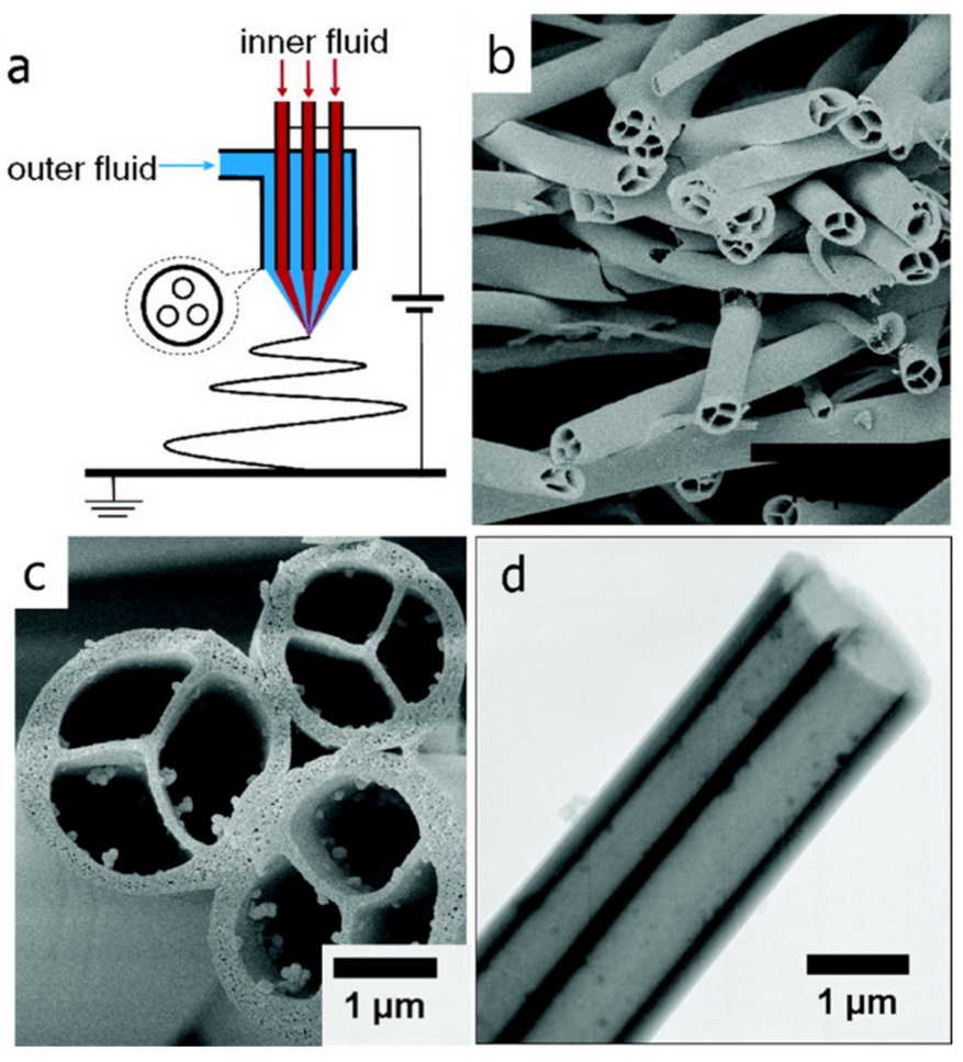
Figure 6. (a) Schematic representation of a three-channel tube manufacturing system with segregated inner and exterior fluid tubes. (b) Side-view SEM image of sample after the removal of organic components. (c) Magnified SEM image of tubes in which the channels were divided into three independent flabellate parts by a Y-shape inner ridge. (d) TEM image of a three-channel tube with straight and continuous channels. Reprinted with permission from Reference [44]. Copyright 2007, American Chemical Society.
2.3. Aligned Nanofibers by Special Collectors
Compared with the original unordered nanofibers, highly aligned nanofibers elicit considerable fascination among researchers on account of the improved performance resulting from their directionality. For example, one recent study indicated that the photoelectric devices made by aligned nanofibers tended to exhibit higher sensitivity than devices fabricated by the common messy nanofibers [45]. Among diverse approaches to realizing the aligned structure of fibers, near-field electrospinning stands out due to the ability to precisely control the positions of deposited nanofibers. Conventional electrospinning is usually conducted in the far-field mode with the distance between the needle and the collector larger than 5 cm, while near-field electrospinning works for a corresponding distance of 500 μm–5 cm, causing the thorough change of the stage at which the fibers will be deposited on the collector. A typical scheme of near-field electrospinning with a movable collector can be seen in Figure 7a [46]. With the decrease in spinning distance, the straight jet was put onto the collector in the absence of whipping instability. On this condition, the electric field between the spinneret and the collector is more concentrated, and the applied voltage and the accordingly flow rate could be reduced. In addition, near-field electrospinning allows for the desired fiber distribution by adjusting the average motion speed of the needle (Sn) and the relative movement speed of the collector (Sc), and this was demonstrated by using an electrospun solution blend of PEO, water, and ethanol [47]. However, when the Sc was smaller than Sn, the oscillation motion of the jet was inevitable, and wild coil fibers were deposited on the collector (Figure 7b). With the increase in the moving speed of the collector to 0.36 m/s, one aligned straight fiber of 0.49 μm diameter was achieved because of the vanishment of the unstable oscillation (Figure 7c). By carefully matching the motion speed of the jet and collector, a specified pattern of the nanofibers could be obtained (Figure 7d,e) [48][49].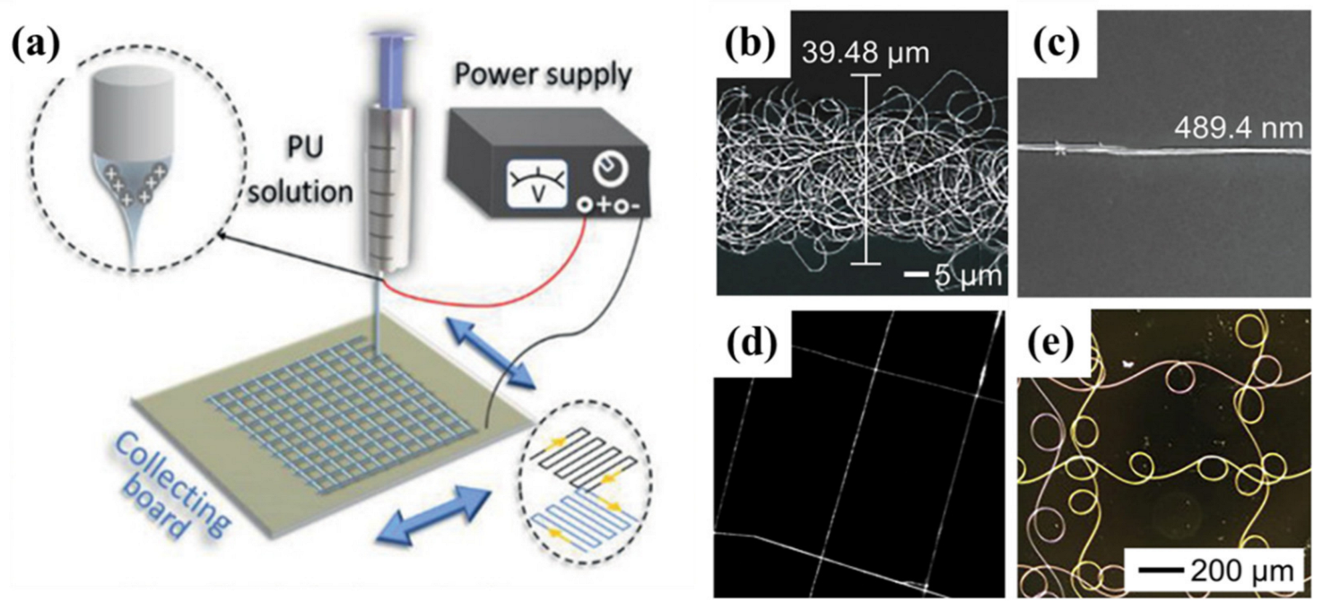
Figure 7. (a) Schematic setup image for near-field electrospinning to directly write fibers on a collecting board. Reprinted with permission from Reference [46]. Copyright 2021 Wiley-VCH GmbH. (b–d) SEM images of the PEO nanofibers were deposited on a silicon substrate when the collector moved at speeds of (b) 0.03 m/s, and (c) 0.36 m/s, respectively. Reprinted with permission from Reference [47]. Copyright 2010 IOP Publishing. (d) SEM image of PEO fibers deposited in a pattern by controlling the motion of the collector along with both X and Y directions during near-field electrospinning. Reprinted with permission from Reference [48]. Copyright 2011, American Chemical Society. (e) The latticed pattern of polystyrene nanofibers by near-field electrospinning. Reprinted with permission from Reference [49]. Copyright 2012 Elsevier Ltd.
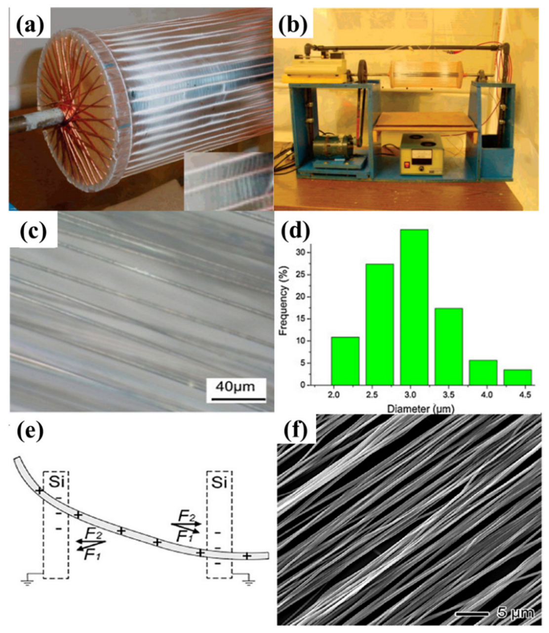
Figure 8. (a) Images of copper wires wrapped disks, where electrospun nanofibers are collected on the copper wires and the magnified inset image shows the aligned nanofiber. (b) Apparatus for rotating the copper wire drum during electrospinning. Reprinted with permission from Reference [50]. Copyright 2004 American Chemical Society. (c) Photograph and (d) histogram showing the size distribution of aligned PMMA fibers. Reprinted with permission from Reference [51]. Copyright 2014 Elsevier B.V. (e) Diagram of the electrostatic forces acted on a charged nanofiber traversing an insulating gap. The electrostatic force (F1) was produced by the electric field while the Coulomb interactions (F2) originated from the positive charges on the nanofibers and the negative charges on the two grounded electrodes. (f) SEM image of the uniaxially aligned PCL nanofibers. Reprinted with permission from Reference [52]. Copyright 2003 American Chemical Society.
2.4. Parameters Affecting Electrospinning
Electrospinning gives the corresponding nanofibers many advantages over conventional film-based planar materials, such as better mechanical characteristics, more flexibility, better uniformity, enhanced electrical properties, more porosity, larger surface area, and ease of synthesis and processing. Nevertheless, its large-scale commercial production still has a long way to go. This sophisticated method involves many technological procedures and appropriate control over the whole electrospinning process is necessary to promote efficiency and fiber performance. The features of electrospun nanofibers are dependent on several parameters falling into three main categories: inner properties of the solution, conditions of the electrospinning process, and surrounding environmental factors. Firstly, solution variables generally contain the molecular weight, viscosity, polarity, concentration, surface tension, electrical conductivity, and elasticity of the solvent. Among them, concentration is a typical factor affecting the morphology and characteristics of the electrospun nanofibers. To form the continuous fibers, a critical concentration should be reached for the occurrence of the electrospinning process. At low concentration, the diameter of nanofibers is smaller on average [53] and what is even worse is the formation of droplets and beaded nanofibers caused by insufficient chain entanglement to stabilize the surface tension of the jet. However, a much higher concentration could also harm the construction of fibers due to the relatively higher viscosity of the solution [54]. Consequently, proper concentration is the key to the formation of uniform and smooth nanofibrous materials, letting the electric field fully override the surface tension. The viscosity and surface tension of the solution impact the electrospinning process and fiber fabrication in the same manner as the concentration: In the solution with too high or low viscosity and surface tension, the formation of fibers will be limited. Thus, suitable parameters are crucial for the production of high-quality fibers. Particularly, the electrospinning process would be applied at lower applied voltages when lower surface tension is achieved [55]. Furthermore, the molecular weight of the targeted material in the electrospun solution plays a critical role in the formation of good nanofibers. With a lower molecular weight, a relatively increased diameter of the fibers appears [10]. Opposite to the anti-dependence of the molecular weight and fiber diameter, increased electrical conductivity of the solution would lead to increased fiber diameter, but a slight decrease would occur later [56]. Conditions of electrospinning process, such as applied voltage, feed rate of the solution, and the distance between the spinneret and the collector, are other influencing factors that belong to the following part to achieve tunable fiber morphology and quality after getting the electrospun solution ready. Particularly, electrospinning variables have a significant connection with the diameter of the fibers. For example, a smaller size of fibers will be collected on the plate with a small inner diameter of the spinneret as a result of the increased surface tension of the charged jet [57]. Then, the acceleration of the jet will be weakened for the need for more energy to overcome the interfacial tension, and more time for the jet to be stretched into a smaller diameter is needed. Besides, a growing flow rate and smaller distance between the needle and the collector will bring increased fiber diameter despite the extreme circumstances [58]. Environmental factors, including ambient humidity and temperature, influence the quality of the jet and its deposited fibers at any time. Studies have reported that high humidity will cause shorter solidification time and in such cases prolong the produced jet, whereas low humidity will lead to too thorough evaporation of the solvents, and the formation of the continuous fibers would be impeded [59]. Environmental temperature is another parameter that impacts the diameter of the nanofibers by controlling the viscosity of the solution [60]. Problematic beads or flat fibers will arise at low or high temperature. Summarized parameters that influence the nanofibers’ characteristics in the electrospinning process are presented in Table 1.Table 1. Parameters influencing the nanofibers’ characteristics in the electrospinning process.
| Category | Detailed Factors | Changes in Nanofibers |
|---|---|---|
| Solution Variables | Target material concentration | Fiber diameter increases with the rising concentration |
| Electrical conductivity of the solution | Fiber diameter increases with the rising conductivity. | |
| Viscosity and surface tension of the solution | Too high or too low factors lead to poor fiber morphology. | |
| The molecular weight of the target material | Fiber diameter decreases with increasing molecular weight. | |
| Conditions of Electrospinning Process | Spinneret inner diameter | Fiber size is smaller with a smaller spinneret inner diameter. |
| Flow rate | High flow rate causes increased fiber diameter. | |
| Distance between the needle and the collector | Smaller distance results in larger fiber diameter. | |
| Environmental Factors | Ambient humidity | High humidity prolongs the produced jet. |
| surrounding temperature | Temperature controls the viscosity of the solution and the fiber size. |
References
- Yang, C.; Chen, M.; Li, S.; Zhang, X.; Hua, C.; Bai, H.; Xiao, C.; Yang, S.A.; He, P.; Xu, Z.; et al. Coexistence of Ferroelectricity and Ferromagnetism in One-Dimensional SbN and BiN Nanowires. ACS Appl. Mater. Interfaces 2021, 13, 13517–13523.
- Li, Y.; Dietrich, S.; Forsythe, C.; Taniguchi, T.; Watanabe, K.; Moon, P.; Dean, C.R. Anisotropic Band Flattening in Graphene with One-Dimensional Superlattices. Nat. Nanotechnol. 2021, 16, 525–530.
- Yin, S.; Liu, S.; Zhang, H.; Jiao, S.; Xu, Y.; Wang, Z.; Li, X.; Wang, L.; Wang, H. Engineering One-Dimensional AuPd Nanospikes for Efficient Electrocatalytic Nitrogen Fixation. ACS Appl. Mater. Interfaces 2021, 13, 20233–20239.
- Tong, Z.; Liao, Z.; Liu, Y.; Ma, M.; Bi, Y.; Huang, W.; Ma, Y.; Qiao, M.; Wu, G. Hierarchical Fe3O4/@MoS2 Core-Shell Nanofibers for Efficient Microwave Absorption. Carbon 2021, 179, 646–654.
- Bai, Y.; Zhou, L.; Wang, J.; Wu, W.; McGilly, L.J.; Halbertal, D.; Lo, C.F.B.; Liu, F.; Ardelean, J.; Rivera, P.; et al. Excitons in Strain-Induced One-Dimensional Moiré Potentials at Transition Metal Dichalcogenide Heterojunctions. Nat. Mater. 2020, 19, 1068–1073.
- Luzio, A.; Canesi, E.; Bertarelli, C.; Caironi, M. Electrospun Polymer Fibers for Electronic Applications. Materials 2014, 7, 906–947.
- Formhals, A. Method and Apparatus for Spinning. U.S. Patent No. 2160962, 6 June 1939.
- Doshi, J.; Reneker, D.H. Electrospinning Process and Applications of Electrospun Fibers. In Proceedings of the Conference Record of the 1993 IEEE Industry Applications Conference Twenty-Eighth IAS Annual Meeting, Toronto, ON, Canada, 2–8 October 1993; IEEE: Piscataway, NJ, USA; pp. 1698–1703.
- Xue, J.; Xie, J.; Liu, W.; Xia, Y. Electrospun Nanofibers: New Concepts, Materials, and Applications. Acc. Chem. Res. 2017, 50, 1976–1987.
- Rahmati, M.; Mills, D.K.; Urbanska, A.M.; Saeb, M.R.; Venugopal, J.R.; Ramakrishna, S.; Mozafari, M. Electrospinning for Tissue Engineering Applications. Prog. Mater. Sci. 2021, 117, 100721.
- Luraghi, A.; Peri, F.; Moroni, L. Electrospinning for Drug Delivery Applications: A Review. J. Control. Release 2021, 334, 463–484.
- Movahedi, M.; Asefnejad, A.; Rafienia, M.; Khorasani, M.T. Potential of Novel Electrospun Core-Shell Structured Polyurethane/Starch (Hyaluronic Acid) Nanofibers for Skin Tissue Engineering: In Vitro and In Vivo Evaluation. Int. J. Biol. Macromol. 2020, 146, 627–637.
- Wang, Z.; Meng, Y.; Cui, Y.; Fan, C.; Liu, G.; Shin, B.; Feng, D.; Shan, F. Low-Voltage and High-Performance Field-Effect Transistors Based on ZnxSn1 − xO Nanofibers with a ZrOx Dielectric. Nanoscale 2018, 10, 14712–14718.
- Lu, T.; Cui, J.; Qu, Q.; Wang, Y.; Zhang, J.; Xiong, R.; Ma, W.; Huang, C. Multistructured Electrospun Nanofibers for Air Filtration: A Review. ACS Appl. Mater. Interfaces 2021, 13, 23293–23313.
- Yang, Z.; Zhang, X.; Qin, Z.; Li, H.; Wang, J.; Zeng, G.; Liu, C.; Long, J.; Zhao, Y.; Li, Y.; et al. Airflow Synergistic Needleless Electrospinning of Instant Noodle-like Curly Nanofibrous Membranes for High-Efficiency Air Filtration. Small 2022, 18, 2107250.
- Fu, Y.; Yu, H.-Y.; Jiang, C.; Zhang, T.-H.; Zhan, R.; Li, X.; Li, J.-F.; Tian, J.-H.; Yang, R. NiCo Alloy Nanoparticles Decorated on N-Doped Carbon Nanofibers as Highly Active and Durable Oxygen Electrocatalyst. Adv. Funct. Mater. 2018, 28, 1705094.
- He, Y.; Guo, H.; Hwang, S.; Yang, X.; He, Z.; Braaten, J.; Karakalos, S.; Shan, W.; Wang, M.; Zhou, H.; et al. Single Cobalt Sites Dispersed in Hierarchically Porous Nanofiber Networks for Durable and High-Power PGM-Free Cathodes in Fuel Cells. Adv. Mater. 2020, 32, 2003577.
- Zhu, S.; Nie, L. Progress in Fabrication of One-Dimensional Catalytic Materials by Electrospinning Technology. J. Ind. Eng. Chem. 2021, 93, 28–56.
- Li, X.; Chen, W.; Qian, Q.; Huang, H.; Chen, Y.; Wang, Z.; Chen, Q.; Yang, J.; Li, J.; Mai, Y.-W. Electrospinning-Based Strategies for Battery Materials. Adv. Energy Mater. 2021, 11, 2000845.
- Zhang, Y.; Zhang, X.; Silva, S.R.P.; Ding, B.; Zhang, P.; Shao, G. Lithium–Sulfur Batteries Meet Electrospinning: Recent Advances and the Key Parameters for High Gravimetric and Volume Energy Density. Adv. Sci. 2022, 9, 2103879.
- Dziemidowicz, K.; Sang, Q.; Wu, J.; Zhang, Z.; Zhou, F.; Lagaron, J.M.; Mo, X.; Parker, G.J.M.; Yu, D.-G.; Zhu, L.-M.; et al. Electrospinning for Healthcare: Recent Advancements. J. Mater. Chem. B 2021, 9, 939–951.
- Praveen, S.; Veeralingam, S.; Badhulika, S. A Flexible Self-Powered UV Photodetector and Optical UV Filter Based on β-Bi2O3/SnO2 Quantum Dots Schottky Heterojunction. Adv. Mater. Interfaces 2021, 8, 2100373.
- Jun, L.; Chen, Q.; Fu, W.; Yang, Y.; Zhu, W.; Zhang, J. Electrospun Yb-Doped In2O3 Nanofiber Field-Effect Transistors for Highly Sensitive Ethanol Sensors. ACS Appl. Mater. Interfaces 2020, 12, 38425–38434.
- Kim, D.-H.; Bae, J.; Lee, J.; Ahn, J.; Hwang, W.-T.; Ko, J.; Kim, I.-D. Porous Nanofiber Membrane: Rational Platform for Highly Sensitive Thermochromic Sensor. Adv. Funct. Mater. 2022, 2200463.
- Balamurugan, R.; Sundarrajan, S.; Ramakrishna, S. Recent Trends in Nanofibrous Membranes and Their Suitability for Air and Water Filtrations. Membranes 2011, 1, 232–248.
- Fadil, F.; Affandi, N.D.N.; Misnon, M.I.; Bonnia, N.N.; Harun, A.M.; Alam, M.K. Review on Electrospun Nanofiber-Applied Products. Polymers 2021, 13, 2087.
- Liao, Y.; Loh, C.-H.; Tian, M.; Wang, R.; Fane, A.G. Progress in Electrospun Polymeric Nanofibrous Membranes for Water Treatment: Fabrication, Modification and Applications. Prog. Polym. Sci. 2018, 77, 69–94.
- Qiao, J.; Zhang, X.; Xu, D.; Kong, L.; Lv, L.; Yang, F.; Wang, F.; Liu, W.; Liu, J. Design and Synthesis of TiO2/Co/Carbon Nanofibers with Tunable and Efficient Electromagnetic Absorption. Chem. Eng. J. 2020, 380, 122591.
- Gao, S.; Wang, N.; Li, S.; Li, D.; Cui, Z.; Yue, G.; Liu, J.; Zhao, X.; Jiang, L.; Zhao, Y. A Multi-Wall Sn/SnO2@Carbon Hollow Nanofiber Anode Material for High-Rate and Long-Life Lithium-Ion Batteries. Angew. Chem. Int. Ed. 2020, 59, 2465–2472.
- Du, H.; Yang, W.; Yi, W.; Sun, Y.; Yu, N.; Wang, J. Oxygen-Plasma-Assisted Enhanced Acetone-Sensing Properties of ZnO Nanofibers by Electrospinning. ACS Appl. Mater. Interfaces 2020, 12, 23084–23093.
- Hu, Q.; Huang, B.; Li, Y.; Zhang, S.; Zhang, Y.; Hua, X.; Liu, G.; Li, B.; Zhou, J.; Xie, E.; et al. Methanol Gas Detection of Electrospun CeO2 Nanofibers by Regulating Ce3+/Ce4+ Mole Ratio via Pd Doping. Sens. Actuators B Chem. 2020, 307, 127638.
- Li, Z.; Meng, Y.; Wang, C.; Cui, Y.; Yao, Z.; Shin, B.; Liu, G.; Shan, F. Enhancement-Mode Field-Effect Transistors Based on Ti-Doped In2O3 Nanowires Fabricated by Electrospinning. J. Phys. D Appl. Phys. 2019, 52, 225102.
- Dai, X.; Li, X.; Wang, X. Morphology Controlled Porous Poly(Lactic Acid)/Zeolitic Imidazolate Framework-8 Fibrous Membranes with Superior PM2.5 Capture Capacity. Chem. Eng. J. 2018, 338, 82–91.
- McCann, J.T.; Marquez, M.; Xia, Y. Highly Porous Fibers by Electrospinning into a Cryogenic Liquid. J. Am. Chem. Soc. 2006, 128, 1436–1437.
- Chen, R.; Huang, C.; Ke, Q.; He, C.; Wang, H.; Mo, X. Preparation and Characterization of Coaxial Electrospun Thermoplastic Polyurethane/Collagen Compound Nanofibers for Tissue Engineering Applications. Colloids Surf. B Biointerfaces 2010, 79, 315–325.
- Han, D.; Steckl, A.J. Coaxial Electrospinning Formation of Complex Polymer Fibers and Their Applications. ChemPlusChem 2019, 84, 1453–1497.
- Xu, D.; Ge, K.; Chen, Y.; Qi, S.; Qiu, J.; Liu, Q. Cable-Like Core–Shell Mesoporous SnO2 Nanofibers by Single-Nozzle Electrospinning Phase Separation for Formaldehyde Sensing. Chem. A Eur. J. 2020, 26, 9365–9370.
- Mendoza-Diaz, M.I.; Garcia-Gutierrez, D.F.; Sepulveda-Guzman, S.; Moreno-Cortez, I.E.; Garcia-Gutierrez, D.I. Tuning the Optoelectronic Properties of PEDOT:PSS-PVP Core–Shell Electrospun Nanofibers by Solvent-Quantum Dot Doping and Phase Inversion. Nanotechnology 2019, 30, 395601.
- Lee, M.Y.; Oh, Y.; Hong, J.; Lee, S.J.; Seong, D.G.; Um, M.-K.; Oh, J.H. Fabrication of Stretchable and Transparent Core–Shell Polymeric Nanofibers Using Coaxial Electrospinning and Their Application to Phototransistors. Adv. Electron. Mater. 2021, 7, 2001000.
- Yan, E.; Jiang, J.; Yang, X.; Fan, L.; Wang, Y.; An, Q.; Zhang, Z.; Lu, B.; Wang, D.; Zhang, D. PH-Sensitive Core-Shell Electrospun Nanofibers Based on Polyvinyl Alcohol/Polycaprolactone as a Potential Drug Delivery System for the Chemotherapy against Cervical Cancer. J. Drug Deliv. Sci. Technol. 2020, 55, 101455.
- Sarvi, A.; Chimello, V.; Silva, A.B.; Bretas, R.E.; Sundararaj, U. Coaxial Electrospun Nanofibers of Poly(Vinylidene Fluoride)/Polyaniline Filled with Multi-Walled Carbon Nanotubes. Polym. Compos. 2014, 35, 1198–1203.
- Niu, H.; Wang, H.; Zhou, H.; Lin, T. Ultrafine PDMS Fibers: Preparation from in Situ Curing-Electrospinning and Mechanical Characterization. RSC Adv. 2014, 4, 11782–11787.
- Duan, G.; Greiner, A. Air-Blowing-Assisted Coaxial Electrospinning toward High Productivity of Core/Sheath and Hollow Fibers. Macromol. Mater. Eng. 2019, 304, 1800669.
- Zhao, Y.; Cao, X.; Jiang, L. Bio-Mimic Multichannel Microtubes by a Facile Method. J. Am. Chem. Soc. 2007, 129, 764–765.
- Song, Y.; Wang, Y.; Xu, L.; Wang, M. Fabrication and Characterization of Electrospun Aligned Porous PAN/Graphene Composite Nanofibers. Nanomaterials 2019, 9, 1782.
- Huang, Y.; You, X.; Tang, Z.; Tong, K.-Y.; Guo, P.; Zhao, N. Interface Engineering of Flexible Piezoresistive Sensors via Near-Field Electrospinning Processed Spacer Layers. Small Methods 2021, 5, 2000842.
- Zheng, G.; Li, W.; Wang, X.; Wu, D.; Sun, D.; Lin, L. Precision Deposition of a Nanofibre by Near-Field Electrospinning. J. Phys. D Appl. Phys. 2010, 43, 415501.
- Bisht, G.S.; Canton, G.; Mirsepassi, A.; Kulinsky, L.; Oh, S.; Dunn-Rankin, D.; Madou, M.J. Controlled Continuous Patterning of Polymeric Nanofibers on Three-Dimensional Substrates Using Low-Voltage Near-Field Electrospinning. Nano Lett. 2011, 11, 1831–1837.
- Xin, Y.; Reneker, D.H. Hierarchical Polystyrene Patterns Produced by Electrospinning. Polymer 2012, 53, 4254–4261.
- Katta, P.; Alessandro, M.; Ramsier, R.D.; Chase, G.G. Continuous Electrospinning of Aligned Polymer Nanofibers onto a Wire Drum Collector. Nano Lett. 2004, 4, 2215–2218.
- Zhang, H.-D.; Tang, C.-C.; Long, Y.-Z.; Zhang, J.-C.; Huang, R.; Li, J.-J.; Gu, C.-Z. High-Sensitivity Gas Sensors Based on Arranged Polyaniline/PMMA Composite Fibers. Sens. Actuators A Phys. 2014, 219, 123–127.
- Li, D.; Wang, Y.; Xia, Y. Electrospinning of Polymeric and Ceramic Nanofibers as Uniaxially Aligned Arrays. Nano Lett. 2003, 3, 1167–1171.
- Bhattarai, R.S.; Bachu, R.D.; Boddu, S.H.S.; Bhaduri, S. Biomedical Applications of Electrospun Nanofibers: Drug and Nanoparticle Delivery. Pharmaceutics 2019, 11, 5.
- Topuz, F.; Abdulhamid, M.A.; Holtzl, T.; Szekely, G. Nanofiber Engineering of Microporous Polyimides through Electrospinning: Influence of Electrospinning Parameters and Salt Addition. Mater. Des. 2021, 198, 109280.
- Haghi, A.K.; Akbari, M. Trends in Electrospinning of Natural Nanofibers. Phys. Status Solidi 2007, 204, 1830–1834.
- Yang, Y.; Jia, Z.; Liu, J.; Li, Q.; Hou, L.; Wang, L.; Guan, Z. Effect of Electric Field Distribution Uniformity on Electrospinning. J. Appl. Phys. 2008, 103, 104307.
- Zhang, H. Effects of Electrospinning Parameters on Morphology and Diameter of Electrospun PLGA/MWNTs Fibers and Cytocompatibility in Vitro. J. Bioact. Compat. Polym. 2011, 26, 590–606.
- Li, Z.; Wang, C. Effects of Working Parameters on Electrospinning. In One-Dimensional Nanostructures: Electrospinning Technique and Unique Nanofibers; Li, Z., Wang, C., Eds.; Springer Briefs in Materials; Springer: Berlin/Heidelberg, Germany, 2013; pp. 15–28. ISBN 978-3-642-36427-3.
- Szewczyk, P.K.; Stachewicz, U. The Impact of Relative Humidity on Electrospun Polymer Fibers: From Structural Changes to Fiber Morphology. Adv. Colloid Interface Sci. 2020, 286, 102315.
- Rodoplu, D.; Mutlu, M. Effects of Electrospinning Setup and Process Parameters on Nanofiber Morphology Intended for the Modification of Quartz Crystal Microbalance Surfaces. J. Eng. Fibers Fabr. 2012, 7, 118–123.
More