Your browser does not fully support modern features. Please upgrade for a smoother experience.
Please note this is a comparison between Version 1 by Xiangdong Kong and Version 3 by Catherine Yang.
The digital hydraulic technology as a system which controls a discrete fluid with a modulated, discrete, digital signal directly to realize active and intelligent control of the system output. The hydraulic components with such technical characteristics can be defined as digital hydraulic components. The system composed by digital hydraulic components can also be defined as digital hydraulic system. What is more, the essential feature of digital hydraulic technology is intelligent control; technology which can only realize on/off control cannot be classified as digital hydraulic technology.
- digital hydraulic technology
- digital hydraulic components
- digital hydraulic system
1. Developments and the Current Situation of Digital Hydraulic Technology
1.1. Parallel Digital Hydraulic Technology
The idea of using multiple hydraulic valves in parallel has existed since the birth of the hydraulic valves. In the document that can be found at present, as early as 1930, Rickenberg applied a patent regarding using three electromagnetic valves with different flow rates in parallel [1][20]. Murphy [2][21] also applied for a patent of a four-way valve for which the load-side is independently controlled by using DFCU. Virvalo [3][22] achieved the application of DFCU in the velocity control of hydraulic cylinder in 1978. However, due to the basic computer technology at that time, the parallel technology was difficult to be applied in practice. With the development of the computer technology, research and applications of the parallel technology are gradually becoming abundant.
1.1.1. Parallel Digital Hydraulic Components
At present, parallel digital hydraulic valve technology is one of the most significant research directions among the parallel digital hydraulic technology. Represented by Tampere University of Technology, the University of Aalborg and the Federal University of the State of Santa Catarina have conducted in-depth research on the parallel digital hydraulic valve technology. Among them, Linjama of Tampere University of Technology and his team put forward the basic definition of DFCU based on ordinary commercial valve earlier, and they tested the dynamic and static characteristics of DFCU [4][5][6][23,24,25].
After that, the team carried out a series aimed at the control strategy [7][8][26,27], pressure peak [9][28], fault detection [10][29] and energy saving [11][12][30,31] of DFCU. And they successfully applied the DFCU to a paper cutting machine; it is superior to the traditional hydraulic system in terms of cost, control performance and energy saving [13][14][32,33]. Now, a new generation DFCU that can integrate more switching valves is being developed [15][34]. Some researchers have carried out research on improving DFCU energy efficiency and fault-tolerant performance, and they also achieved some results [16][17][9,35].
The research of the parallel digital hydraulic actuator mainly centers on the hydraulic cylinder. Tampere university has studied the impedance control of a three-piston parallel digital hydraulic cylinder, and the experimental results show that the energy loss of the parallel digital hydraulic cylinder in the system with constant input pressure is reduced by 30%–60% compared with the traditional hydraulic cylinder [18][45]. At the same time, Linjama also found that when adopting the secondary regulation hydraulic source without throttling, the parallel digital hydraulic cylinder can achieve better energy saving effect, and this conclusion was verified by the experiment of a four-piston parallel digital hydraulic cylinder [19][46].
1.1.2. Application of the Parallel Digital Hydraulic Technology
The parallel digital hydraulic technology is mainly used in two aspects: direct parallel control of components and applications of parallel digital valve.
The application of the parallel digital valve is the main research direction of parallel digital hydraulic technology. Bishop E. has developed a parallel linear hydraulic transformer with unique advantages over traditional hydraulic transformers in terms of pressure ratio, response time and transfer efficiency [20][48]. The team of Tampere University of Technology creatively has put forward the definition of digital hydraulic momentum control system (DHPMS), and published its simulation analysis results for the first time in 2009 [21][22][49,50], and their experimental analysis results were published in the following year. The results show that DHPMS has obvious advantages in terms of control performance and energy efficiency [23][51]. At present, the research and development of the second generation DHPMS (which is shown in Figure 125) have also made breakthroughs [24][52].
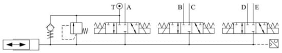
Figure 125.
Schematic diagram of second generation DHPMS.
Johan Ersfolk optimized the parallel digital valve control of hydraulic cylinders by using a modern embedded graphics processing unit (GPU), and the results showed that the large-scale parallel characteristics brought by the GPU enabled the controller to obtain better control performance than conventional controllers [25][53].
1.2. High-Speed Switching Digital Hydraulic Technology
The automobile industry has greatly promoted the development of high-speed switching digital hydraulic technology. The high-speed switching valves which can turn on and off more than 1000 times per second are the first and the most widely applied in the ABS braking system [26][27][54,55].
The high-pressure fuel injection technology which emerged around the year of 2000 put forward a series of technical requirements for high-speed switching valve. Since the working pressure is 200 Mpa, it requires that the valve can realize five times on/off switching for each combustion. And the valve failures are not allowed during vehicle service. Although the high-speed switching solenoid valve in the automobile industry generally has a small flow rate and is not suitable for hydraulic system, its successful promotion and application have proved that the high-speed switching technology is feasible and reliable. And that is the reason why some valves in the automobile industry are mentioned below when the high-speed switching digital hydraulic valve is introduced.
1.2.1. High-Speed Switching Digital Hydraulic Valve
The research of high-speed switching hydraulic technology focuses on the R&D of high-speed switching valves, which has two aspects. The one is the research and development of new high-speed switching valves, and the other is the control method of high-speed switching valves.
The development of the high-speed switching valve can be traced back to the end of the 1970s. The company Lucas in Britain developed the high-speed solenoid switching valve using two special shape electromagnets: spiral tube type and taper type, which were called the “Helenoid valve” and “Colenoid valve.” They overcame the problem that the acceleration of armature is inversely proportional to electromagnetic force.
But due to their complicated structures and difficulty in processing and manufacturing, they are not widely used [28][29][56,57]. Since then, many companies and research institutions launched various types of high-speed switching valves. BKM company launched a three-way spherical, cartridge type, high-speed electromagnetic switching valve with a response time of 2–3 ms, and its working pressure is 10 MPa [30][58]. But this valve can only be used for direct digital control of electronic unit injectors because of its small flow rate. Yukio Tanaka developed a two-way high-speed switching valve and a three-way high-speed switching valve in the 1980s; their response times are all around 3 ms [31][59].
In the late 1980s, Masahiko Miyamoto developed an ultra-high-pressure high-speed switching valve with working pressure of 120 MPa and response time of 0.4 ms [32][33][34][60,61,62]. However, because these valves do not overcome the small flow rate, their applications are limited to the field of fuel injection. Bosch company also successfully developed a high-speed electromagnetic switching valve suitable for an ultra-high-pressure environment, and its response time is between 0.3 and 0.65 ms [35][63]. Linz center developed a high frequency switching ball valve which is shown in Figure 26a, and the spool is controlled by current feedback. The spool position of this valve is only 5 mm, and its frequency response is up to 1 kHz; its flow rate can reach 14 L/min [36][64]. But for now, the exemplary application for such a valve could be the actuation of automotive wet clutches; in particular, those of dual clutch systems. Tampere optimized the surface material and the heat-treatment process of the cone valve, and they obtained a high-speed switching water hydraulic valve with high reliability and long service life (which is shown in Figure 26b) [37][65]. Minnesota university developed a rotary high-speed switching valve with a special structure pilot spool which is shown in Figure 26c; this valve’s maximum flow rate is 40 L/min, and its frequency response is 100 Hz [38][66]. Zhejiang University designed a PZT piezoceramic high-speed switching valve with temperature compensation, which is shown in Figure 26d. This valve’s working pressure can reach 20 MPa, and its frequency response and flow rate are, respectively, 200Hz and 10 L/min [39][67]. Guizhou Honglin machinery factory cooperated with BKM company developed a thread cartridge HSV high-speed electromagnetic switching valve, whose opening time is 3 ms, and closing time is 2 ms. This valve ‘s highest working pressure is 20 MPa, and its flow rate can reach 2–9 L/min [40][68].
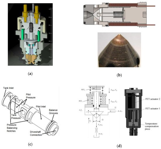
Figure 26. New high-speed switching valves: (a) Linz high frequency switching valve; (b) Tampere hydraulic water valve; (c) rotation pilot spool; (d) PZT piezoceramic high-speed switching valve.
Zhejiang University of Technology developed a high-speed switching valve with a high frequency and large flow rate. This valve’s working pressure is 21 Mpa, and its flow rate is 450 L/min. The spool position of the valve reaches 6 mm, but the response time is only about 8 ms [41][69].
The control of high-speed switching valve has a crucial effect on its performance, but few commercial controllers can be used for high-speed switching valve at present [42][43][70,71]. To solve such a problem, Linjama developed a set of controllers with response time of 8–12 ms that can directly control the cartridge valve [31][59]. Zhejiang University put forward an intelligent voltage control method based on current feedback. The self-adaptability of coil resistance makes the excitation time of each voltage segment vary adaptively with the change of coil resistance. And such a control method keeps the dynamic characteristics of the valve at a high level during its working procedure [44][72]. Wuhan University proposed a zero-flow switching control method, which enables the spool of high-speed switching valve to always switch at the zero-flow point; it avoids the pressure impact and energy loss caused by high-frequency switching [45][73].
1.2.2. Applications of High-Speed Switching Hydraulic Technology
Because the current high-speed switching valves generally have a small flow rate, they are mostly used as the pilot control parts of other hydraulic components to achieve hydraulic components’ intelligent digital. Among them, the pilot control of a proportional valve emerged in the 1990s as a successful example [46][47][48][74,75,76].
With the continuous development of high-speed switch technology, its application is gradually widespread. Minnesota University used high-speed switching valves to control the input/output of each piston chamber of a low-speed radial hydraulic motor with large torque (which is shown in Figure 327a). And so far, such a digital motor is used as part of a 7 MW wind turbine drive train (which is shown in Figure 327b). The application of high-speed switching valves improves the energy efficiency of the hydraulic motor [49][77]. Tyler Helmus also adopted a similar method to control the hydraulic pump-motor, and he also achieved excellent control effect of the pump-motor [50][78].
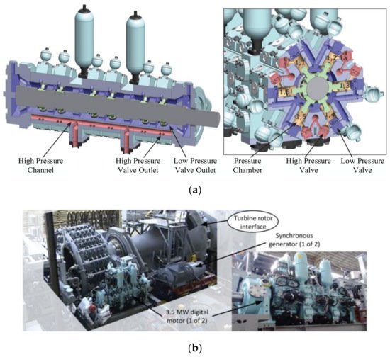
Figure 327. (a) High-speed switching valve controlled hydraulic motor; (b) 7 MW wind turbine drive train using a large scale digital hydraulic pump and two digital motors.
Yang huayong proposed a variable axial piston pump control method (which is shown in Figure 428) using high-speed switching valve for pilot control, and the experimental results proved that this method also has excellent control effect [51][79].
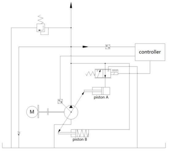
Figure 428.
High-speed switching valve controlled variable axial piston pump.
Rainer Haas used different high-speed switching valve layouts to carry out position control of the hydraulic cylinder (which is shown in Figure 529). And he analyzed the position and speed response of the hydraulic cylinder with different control strategies [52][80].
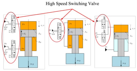
Figure 529.
Position and speed control of the hydraulic cylinder.
Scheidl and his research team carried out a series of studies on the control method and energy-saving of high-speed switching hydraulic torque converters. Among them, one small torque converter obtains an average efficiency of 80% when the maximum output power is 1 kW [53][54][55][18,81,82]. Marcos Paulo Nostrani used the high-speed switching technology to control the hydraulic transformer, and they reduced its energy consumption effectively [56][83]. Shi Guanglin realized precise control of the pneumatic robot by using high-speed switching valves [57][84].
1.3. Stepping Digital Hydraulic Technology
The development of the stepping digital hydraulic technology is thanks to the mature stepping motor technology. Especially after the 1980s, the stepping motor control method was more flexible and diverse because the cheap microcomputer with multiple functions had appeared in industry. Therefore, the stepping motor gradually met the functional requirements of controlling hydraulic components [58][85]. But there are still some problems, such as the lower rotation speed, the small torque, falling out-of-step under high frequency, etc. So, the development and popularization of stepping digital hydraulic technology are still limited. What is more, with the development and perfection of parallel digital hydraulic technology and high-speed switching hydraulic technology, the research on the stepping digital hydraulic technology are gradually reduced.
1.3.1. Stepping Digital Hydraulic Components
The R&D of the stepping digital hydraulic valve is more advanced in Japan, and relevant studies and applications have also been carried out in France, Britain, Canada and other countries [59][60][61][86,87,88]. Among them, the stepping-type digital flow valve and pressure valve of Tokyo Keiki formed a complete product line. The pressure of the valves can reach 210 Mpa, and the flow rate is 1–500 L/min. And the repeatability accuracy and hysteresis accuracy are less than 0.1% [62][89]. In addition, the companies Yuken, Toyooki, Uchida, Sperry, Vickers, Danfos, Beijing Aemetec Digital Hydraulic Ltd., etc. produced stepping digital hydraulic valve products.
Among them, a 2D digital hydraulic valve developed by Zhejiang University of Technology is the most distinctive. The spool of this valve has dual degrees of freedom; one is the rotation around the axis, and the other is the linear motion along the axis. Stepping motor drives the spool to rotate in a certain angle range through the transmission mechanism to realize the function of the pilot valve. And there is a spiral groove on the inner surface of the valve sleeve, the linear motion of the spool is driven by the area difference between the low-pressure hole, the high-pressure hole and the spiral groove to realize the function of the main valve. Its working principle is shown in Figure 630 [63][90]. At present, 2D digital hydraulic valve has formed a relatively complete product series, and they have already been put into service in the aviation industry.
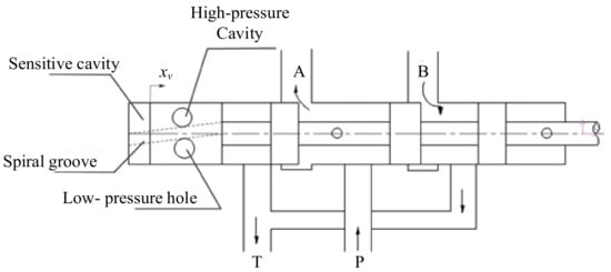
Figure 630.
Working principle of 2D digital hydraulic valve.
Research on stepping digital hydraulic cylinder began in the 1960s and 1970s; the world’s first digital hydraulic cylinder was exhibited in Olympia Hall by Germany. Since then, the company of Rexroth, Tokyo Keiki, Beijing Aemetec Digital Hydraulic Ltd., etc. have developed a variety of stepping digital hydraulic cylinders with various structures [64][91].
1.3.2. Applications of Stepping Digital Hydraulic Technology
The most important applications of stepping digital hydraulic technology are the use of customized digital hydraulic cylinders/valves to achieve accurate position/speed control in extreme environments. At the same time, accurate synchronization control of multiple hydraulic cylinders has also been widely applicated. Among them, the most representative digital cylinder/valve products come from Beijing Aemetec Digital Hydraulic Ltd. (Beijing, China); their products have been successfully applied in a number of military engineering, large water conservancy engineering and metallurgical engineering applications [65][66][67][92,93,94]. For example, a stepping digital hydraulic cylinder is used for the crystallizer liquid level automatic control system (which is shown in Figure 731).
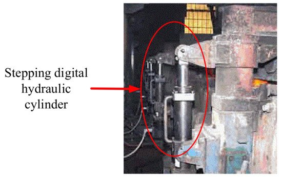
Figure 731.
Practical application of digital hydraulic cylinder.
2. Developing Trend of the Digital Hydraulic Technology
After decades of research, digital hydraulic components have formed a series of products with complete functions and various categories. Some products have been used in aerospace, construction machinery, shipbuilding industry and other industries; its technology has become increasingly mature. However, under the development trend of high speed, high pressure and high power to weight ratio of hydraulic system, the problems such as lower flow rate, lower allowable pressure and serious dispersion of system have also become more prominent. To solve such problems, researchers have also invested a lot of energy into optimizing the existing digital hydraulic products. Some of the research results have not only been applied in engineering, but also evolved into some developmental direction of digital hydraulic technology.
2.1. Development of a New Valve Prototype
High-speed switching digital hydraulic technology puts forward the technical index of switching frequency 500 Hz (that means the opening time is 2 ms) for high-speed switching valve. However, the flow rate of the current valve which can reach such a technical index is generally small. So, the valves cannot satisfy the need of continuous switching control under large flow. Therefore, many research institutions and universities have invested a lot of resources in the R&D of new valves, and they had put forward different valve prototypes, but few valve products can be put into industrial applications. It can be concluded that the R&D of new high-speed switching valves with high working pressure and large flow rate will become an inevitable trend of digital hydraulic technology.
2.2. Integration of Digital Hydraulic Technology
Parallel digital hydraulic technology and high-speed switching digital hydraulic technology, are two main branches of current digital hydraulic technology; they have their own unique technological advantages and face different challenges. Therefore, it is also a research direction of digital hydraulic technology to combine the two main branches of current digital hydraulic technology and take their respective advantages. For example, Huova replaced the smallest switching valve unit in DFCU with high-speed switching valve, which successfully reduced the pressure impact of single high-speed switching control. At the same time, they also obtain accurate speed control of hydraulic cylinders [68][95].
2.3. Improvement of Energy Efficiency
One of the important characteristics of digital hydraulic technology which is different from traditional hydraulic technology, is that it can realize intelligent hydraulic energy supply based on the system requirements. So, digital hydraulic components, such as the digital hydraulic pump-motor, digital hydraulic transformer, DHPMS etc., all have high energy efficiency in theory, but that still needs a lot of experimental verification and optimization. Therefore, improving energy efficiency is also an important development trend of digital hydraulic technology.