Specialty fibers have introduced new levels of flexibility and variability in distributed fiber sensing applications. In particular, distributed acoustic sensing (DAS) systems utilized] the unique functions of specialty fibers to achieve performance enhancements in various distributed sensing applications.
1. Introduction
Acoustic sensors allow people to analyze media through acoustic information. With the increases in the range and scale of acoustic detection, the demand for distributed high-capacity acoustic sensors is also expanding. Furthermore, distributed acoustic sensing (DAS) has become a research hotspot because of its advantages in terms of anti-electromagnetic interference, high sensitivity [1][8], and the small volume and light weight of the systems. DAS is a rising acoustic sensing technology that uses passive optical fibers as the transmission and sensing medium at the same time, squeezing information from optical fiber Rayleigh backscatters to achieve acoustic detection in the surrounding environment. Most DAS systems are based on phase-sensitive optical time domain reflectometry (φ-OTDR), since the phase change in Rayleigh backscattered light has a linear relationship with the acoustic wave acting on the optical fiber [2][9].
Common DAS systems usually use a single-mode fiber (SMF) as the sensing fiber. However, with such fibers the Rayleigh backscattered light is extremely weak and the signal-to-noise ratio (SNR) of the optical sensing signal is low, which leads to a poor SNR of the demodulation phase signal in DAS systems based on φ-OTDR [3][10]. In addition, since a laser pulse with a narrow linewidth and high coherence is injected into the fiber, the interference between the Rayleigh scattering points in one pulse will produce interference cancellation, resulting in coherent fading of the backscattered light, forming a “dead zone” on the sensing fiber [4][11]. In recent years, in order to solve the defects of the poor SNR values and the sensitivity of phase demodulation in SMF-DAS systems, many suppression technologies for noise have been studied, such as coherent fading, while at the same time the complexity and cost of the systems has increased, leading to sacrifices in terms of the response frequency band and sensing distance [5][6][7][8][9][10][11][12,13,14,15,16,17,18]. Furthermore, it is also important to enhance the performance of the sensing fiber itself. The development of a specialty fiber for DAS technology will have broad prospects.
2. Fundamental Principle
2.1. Principle of DAS Technology
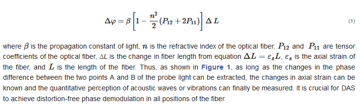
DAS is achieved by measuring the optical phase change caused by the axial strain variation of the optical fiber
[12][19]. When the sound wave acts on the fiber, the fiber will produce axial strain, which changes the phase of the Rayleigh backscattering signal in the fiber. According to the photoelastic effect, there is a linear relationship between the axial strain and the optical phase change:
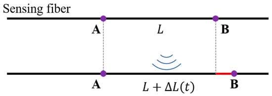
where is the propagation constant of light, n is the refractive index of the optical fiber, and are tensor coefficients of the optical fiber, ∆L is the change in fiber length from equation , is the axial strain of the fiber, and is the length of the fiber. Thus, as shown in Figure 1,. as long as tThe changes in the phase difference between the two points A and B of the probe light can be extracted, the changes in axial strain can be known and the quantitative perception of acoustic waves or vibrations can finally be measured. It is crucial for DAS to achieve distortion-free phase demodulation in all positions of the fibersensing principle of the fiberoptic DAS.
Figure 1. The sensing principle of the fiberoptic DAS.
Since Rayleigh scattering is an elastic scattering method without any nonlinear effect, and as the Rayleigh scattered light at different positions can be distinguished via the time of reflection back to the fiber launch end, the optical fiber phase extraction technique based on phase-sensitive optical time domain reflection (φ-OTDR) is widely used in DAS systems
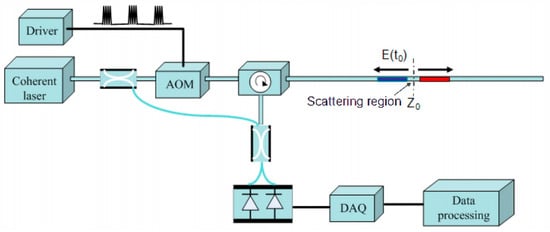
[13][14][20,21]. In 2011, using heterodyne coherent detection technology, the phase of the Rayleigh scattering signal was successfully demodulated for the first time
[15][22]. The scheme of the heterodyne coherent detection is shown in
Figure 2. The local oscillator light and the Rayleigh scattering signal at point A can be expressed as:
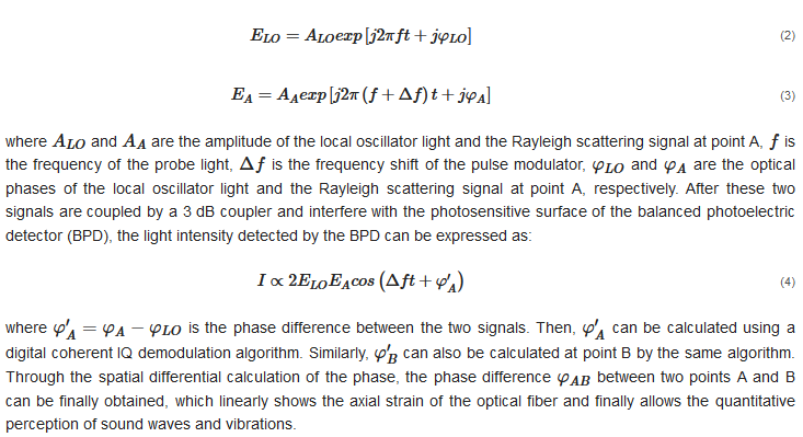
whereFigure 2. and are the amplitude of the local oscillator light and the RaTyleigh scattering signal at point A, is the frequenicy of the probe light, is the frequency shift of the pulse modulator, and are the optical phases of the local oscillator light and the Rayleigh scattering signal at point A, respectively. After these two signals are coupled by a 3 dB coupler and interfere with the photosensitive surface of the balanced photoelectric detector (BPD), the light intensityeterodyne coherent detected by the BPD can be expressed as:
where i
s the phase difference between the two
signals. Then, can be calculated un s
ing a digital c
oherent IQ demodulation algorithm. Similarly, can also bheme
calculated at point B by the same algorithm[22].
Through the spatial differential calculation of the phase, the phase difference between two points A and B can be finally obtained, which linearly shows the axial strain of the optical fiber and finally allows the quantitative perception of sound waves and vibrations.
Figure 2. Typical heterodyne coherent detection scheme [15].
2.2. Limitations of Single-Mode Fiber (SMF) DAS
Despite SMF DAS technology having been applied in many fields, such as geological monitoring, pipeline monitoring, and oil exploration, and with the advantages of distributed detection, high spatial resolution, and high sensitivity, it still has been limited by interference fading and poor signal consistency.
3. Specialty-Fiber-Based DAS Technology
In order to solve the interference fading and poor consistency in SMF DAS, researchers have conducted a series of studies [6][16][17][18][19][13,27,28,29,30]. Among them, the most effective method is to improve the fibers to enhance the fiber backscattering, such as continuous scattering-enhanced fibers and discrete scattering-enhanced fibers formed by inscribing microstructures into the fibers. In addition, due to the characteristics of microstructure optical fibers, researchers also designed and improved the matching optical scheme to improve the performance of the DAS system.
3.1. Continuous Scattering-Enhanced Fiber-Based DAS
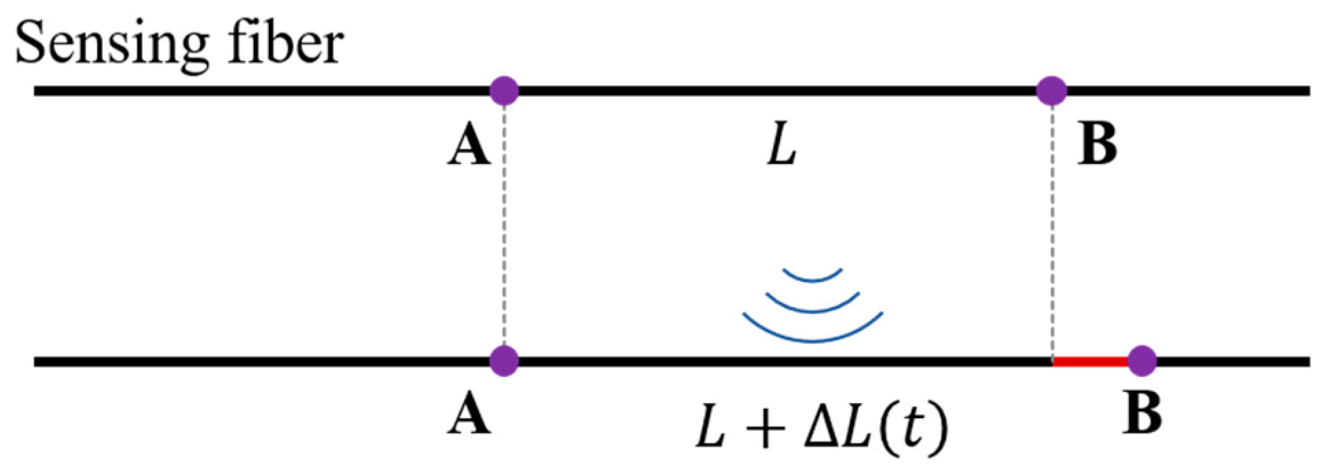
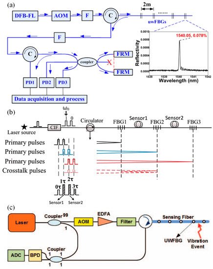
In 2017, the OFS laboratory in the United States used the phase mask method to efficiently and continuously inscribe Bragg gratings in multicore fibers through ultraviolet (UV) exposure. The backscattering intensity of the fiber was increased by 14 dB, and the reflection spectrum is shown in
Figure 35a. Then, in cooperation with Fotech in the UK, CSE fiber was used in a DAS system, and the SNR of 1 km of CSE fiber was increased by 15 dB
[20][21][22][23][31,32,33,34]. Although this method effectively improves the SNR, the bandwidth of the Bragg grating reflection spectrum is narrow, and the reflection wavelength will drift with temperature and stress variation. When the external environment changes, the wavelength of the incident light and grating reflection may not correspond to each other, resulting in the loss of the scattering enhancement effect. Therefore, the application range of this kind of fiber is limited and cannot be used in fields where high temperature and high pressure are required on site. In addition to inscribing continuous gratings, changing the fiber doping is another way to increase the intensity of the Rayleigh scattering. In 2018, Butov et al. used nitrogen-doped fiber as the sensing fiber, which increased the SNR of the acoustic wave detection by 3 dB
[24][35]. In the same year, Feng S et al. used an erbium-doped optical fiber for distributed optical fiber sensing, adopted a phase-generated carrier (PGC) optical scheme, which converts homodyne interference into heterodyne interference by modulating the frequency of the signal, decreased the phase noise by 14 dB, and achieved a high-SNR acoustic measurement on 1.9 km optical fiber
[25][36].
Figure 35. Typical scheme of continuous scattering-enhanced optical fiber
[22][25][33,36]: (
a) the backscattering signal distribution of a typical continuous scattering-enhanced fiber; (
b) scheme of improved Rayleigh scattering achieved by changing the fiber doping; (
c) scattering spectrum of high Rayleigh scattering fiber.
For the CSE scheme, although it can effectively improve the scattering intensity and suppress the coherent fading noise, the enhanced fiber scattering results in doubling of the light loss, which greatly limits the detection distance. Taking the optical fiber doping scheme as an example, if the front-end SNR is increased by 10 dB, the Rayleigh scattering of the fiber needs to be increased by ten times, which reduces the detectable distance to 1/10. More importantly, the SCE fiber does not fundamentally change the nature of the optical interference in the pulse, and still cannot completely eliminate the coherent fading phenomenon.
3.2. Discrete Scattering-Enhanced Fiber Based DAS
In addition to continuous scattering enhancement, more researchers are focusing on the application of discrete scattering-enhanced (DSE) fiber in DAS. As shown in
Figure 46.
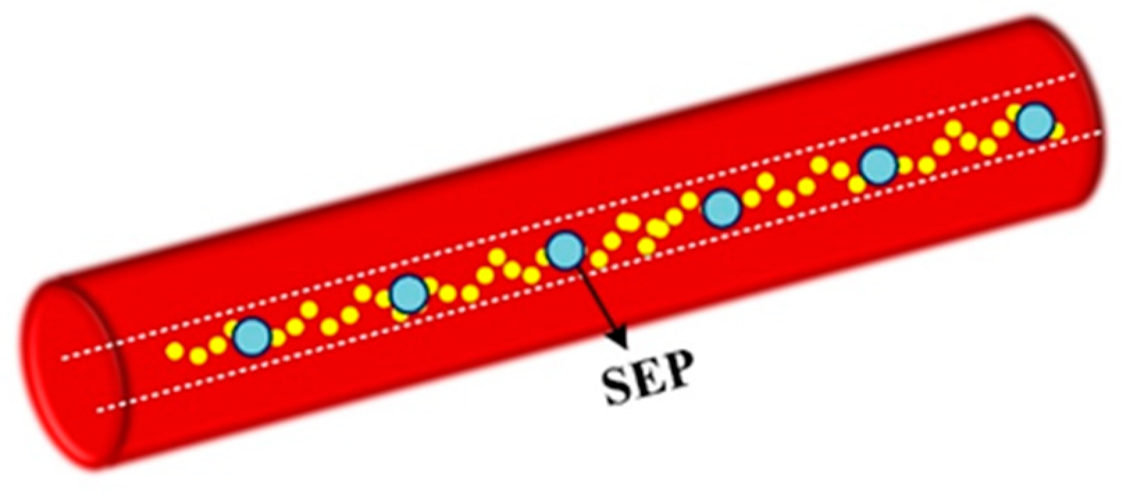
Figure 46.
Schematic diagram of discrete scattering-enhanced fiber.
3.3. Preparation and Implementation of DSE Fiber
At present, there are two ways to manufacture the discrete scattering-enhanced fiber, one is by inscribing the periodic ultra-weak Bragg grating (UWFBG) array
[18][26][29,37] into the fiber, and the other is by introducing a local wavelength-independent weak reflection array into the fiber
[27][28][29][38,39,40].
UWFBG usually involves the use of ultraviolet light
[30][31][32][41,42,43] or a femtosecond laser
[33][34][44,45] to form a permanent periodic change in the refractive index of the optical fiber, so as to allow the backward reflection of a specific light wavelength. The most classic preparation system is shown in
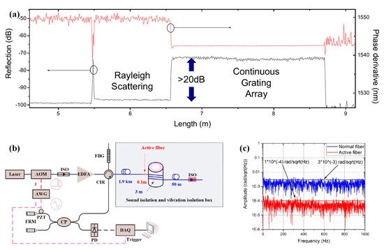
Figure 58a
[35][46]. In the process of fiber drawing, through strict dynamic control, the UWFBG was written using the phase mask method, using periodic interference fringes of the ±1st diffraction light to irradiate the photosensitive fiber and periodically change the refractive index of the fiber core. Additionally, an FBG writing platform was mounted on the draw tower near the first coating to weaken vibrations in the fiber. The preparation results are shown in
Figure 58b
[36][47], and the scattering rate of the scattering-enhanced array is much higher than that of the single-mode fiber. However, as a Bragg grating method, UWFBG is sensitive to temperature and stress. When the temperature and strain of the environment are changed, the reflection wavelength of the UWFBG will drift. As shown in
Figure 58c, the bandwidth of UWFBG is usually less than 2 nm and the central wavelength is determined according to the light source used in the specific experiment. Due to the limited bandwidth of UWFBG, there may be a mismatch between the reflective spectrum of UWFBG and the wavelength of the detection light when the UWFBG array fiber operates in special environments, such as for large temperature vibrations or high pressure, while the fiber will also suffer from twisting or pulling forces, meaning the reflection power from the UWFBG will degenerate into Rayleigh scattering, resulting in a blind sensing area. This characteristic of UWFBG hinders its application in underground, underwater, and other special environments
[37][38][48,49].
Figure 58. Typical UWFBG preparation method: (
a) online UWFBG preparation system
[35][46]; (
b) OTDR measurement results of the UWFBG array
[36][47]; (
c) reflection spectrum of UWFBG
[35][46].
3.4. Methods to Improve the Performance of Specialty Fiber DAS
In the early stages, researchers mainly focused on using UWFBG in various DAS schemes. In 2015, Wang et al. used UWFBG in DAS based on a 3 × 3 coupler demodulation for hydroacoustic testing, which can detect a water pressure of 0.112 Pa
[39][55]. Subsequently, the team at Huazhong University of Science and Technology successively used DSE fiber in various DAS schemes, such as double-pulse, coherent detection, and PGC demodulation schemes
[18][28][29][40][41][42][43][29,39,40,50,56,57,58]. These schemes are shown in
Figure 611. In recent years, more attention has been paid to improving the DAS system performance by using the advantages of discrete scattering enhancement fiber, including low-frequency phase shift compensation, polarization fading suppression, pulse width compression, and system sampling rate expansion.
Figure 611.
Representative DAS scheme based on UWFBG: (a) scheme using a 3 × 3 coupler [44]; ( ) scheme using a 3 × 3 coupler [54]; () PGC scheme [55]; (c) heterodyne coherent detection scheme [18]. ) heterodyne coherent detection scheme [29].
4. Significant Application Progress
4.1. Geological and Resource Exploration
The vertical seismic profile (VSP) is a commonly used parameter for petroleum exploration seismic observations. With the development of DAS technology, fiberoptic logging has become a research hotspot.
Sun et al. conducted a walkaway VSP experiment using a self-made microstructure fiber DAS system
[45][75]. The microstructure fiber is arranged vertically in the test well and the explosive source is artificially introduced on the ground to generate seismic waves, which are transmitted along the stratum to generate direct waves and reflected waves.
4.2. Structural Health Monitoring
The health status of various infrastructure, such as railways, tunnels, and pipelines, is related to operational safety, the national economy, and social production. The DAS system based on scattering-enhanced fibers was applied to the field of structural health monitoring to ensure high reliability.
4.2.1. Pipeline Monitoring
The transportation of resources such as oil and natural gas is closely related to the national economy and people’s lives, but transmission pipelines may fail due to external invasion, corrosion, and other reasons, threatening the safety of personal, profits, and property. The DAS system based on discrete enhanced optical fibers was applied for pipeline safety monitoring due to its high SNR and high stability
[46][47][77,78].
4.2.2. Track Defect Monitoring
With the development of high-speed railway technology, track defect monitoring has become more important. A variety of mature detection methods have been developed, but most of them involve electromagnetic sensors, which are vulnerable to harsh environments
[48][80]. In 2019, Sun et al. used a DAS system based on scattering-enhanced fibers for distributed detection of a railway defect
[49][81].
4.2.3. Tunnel Safety Monitoring
In addition, the health of infrastructure such as tunnels is related to the traffic operation safety. An optical fiber DAS system can also be used for safety detection in tunnels, such as in subways and highways. However, the effectiveness of the reinforcement segment and steel loop in the tunnel structure maybe be a problem. The partial separation of the segment and steel loop will mean the steel loop is unable to effectively support the segment, resulting in potential safety hazards. A resonant cavity will be formed between the segment and the steel loop due to the separation, with different degrees of invalidity corresponding to the different resonant frequencies. In 2021, Sun et al. carried out intelligent monitoring of a tunnel steel loop structure based on a scattering-enhanced optical fiber DAS system
[49][81].
4.2.4. Geological Structural Monitoring
In recent years, DAS monitoring has been used for geological structures
[50][82]. In 2017, a team from the University of California Berkeley transformed fiberoptic telecommunication cables into sensor arrays enabling meter-scale recording over tens of kilometers of linear fiber length to record the nearly vertically incident arrival of an earthquake from the Geysers Geothermal Field and to estimate its backazimuth and speed
[51][83]. In 2018, Jousset et al. demonstrated the possibility of dynamic strain determination with conventional fiber cables deployed for telecommunication
[52][84]. Then, by using DAS, they recorded seismic signals from natural and man-made sources with 4 m spacing along a 15-km-long fiber cable, identifying new dynamic fault processes with unprecedented resolution, opening a new path for earth hazard assessments and the exploration of structural features.
4.3. Hydroacoustic Exploration
Ocean exploration is of great significance to homeland security and resource exploration. The acoustic medium can carry a wealth of information and can transmit signals for long distances underwater, so hydrophones are an important tool for underwater information acquisition. Optical fiber sensors have been preliminarily used in the field of underwater acoustic measurement due to their unique advantages. Single-point sensors and hydrophone arrays based on FBG and interferometers were common methods used for early optical fiber hydrophones. However, due to the limited multiplexing capacity, it is difficult to meet the requirements for large-scale exploration in the ocean and other application environments. In recent years, the DAS system has been well applied in the field of terrestrial acoustic detection. Because of its distributed, long-distance, and high-sensitivity characteristics, the DAS system has been introduced into the field of hydrophones. In the preliminary stage, researchers measured the underwater acoustic sensitivity and other parameters of an optical fiber in the laboratory. Usually, a distributed underwater acoustic sensing system is built based on a UWFBG array and unbalanced interferometer demodulation structure
[44][53][54,87]. The underwater acoustic signal is obtained by demodulating the change in phase difference between two adjacent UWFBGs, in which the sensitivity obtained usually reaches about −160~−150 dB re rad/μPa.