- simulation
- nanomaterials
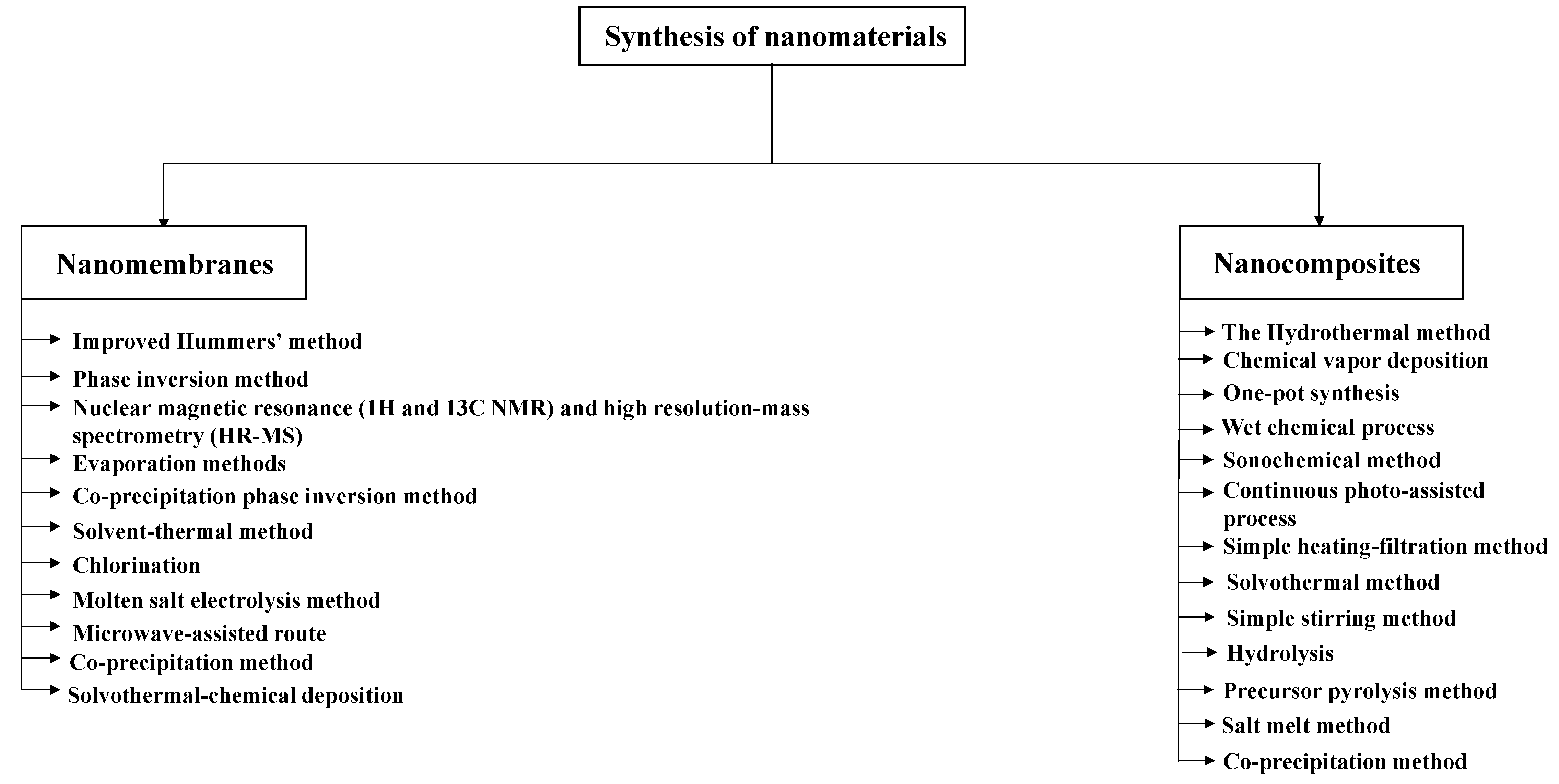
- synthesis
1. Introduction
2. Nanomembranes
2.1. Synthesis of Nanomembranes
| Membrane | Material Type | Synthesis Method | Reference | |||||
|---|---|---|---|---|---|---|---|---|
| Mathematical Model | Reference | |||||||
|
SWCNTs |
Carbon nanotube (CNT) |
Obtained from Cheap Tubes, Inc. |
[21] |
|||||
| (O-CNTs), (G-CNTs) | Gaussian 09W | DFT (B3LYP functional group) | Integral Equation Formalism Polarized Continuum Model (IEFPCM) | [48 | ||||
|
Graphene oxide |
Oxidized graphene oxide |
Obtained commercially from Sigma Aldrich |
[22] |
|||||
| ] | ||||||||
| Graphene | VASP | DFT (PAW) | Kohn-Sham equations | [25] |
ZnO surface |
Zinc oxide (ZnO) |
Evaporation methods |
[23] |
| Graphene oxide | SIESTA code | DFT (LDA) | Kohn-Sham equations | [22] |
MnFe2O4 nanocubes |
Manganese ferrite nanoparticles (MnFe2O4) |
Co-precipitation phase inversion method |
[24] |
| MGOA | Gaussian 09 | DFT (B3LYP functional group) | Thomas, Yoon–Nelson, and Adams–Bohart models | [26] |
Graphene |
|||
| PyTTA-Dva-COF |
3D foam graphene |
Obtained commercially |
[25] |
|||||
| Gaussian 09 | DFT (B3LYP functional group) | ONIOM model | [ | 27] |
MGOA |
Graphene oxide (GO), ammonium (NH4+) |
Modified Hummers’ method |
[26] |
| Vertically aligned (VA) CNT (open-end) hybrid membrane | DMOL3 package | DFT (PW91) | Exchange-Correlation functional | [49] |
PyTTA-Dva-COF |
Nitrogen (N), covalent organic framework |
Solvent-thermal method |
[27] |
| Ultrafiltration PSF/GO membrane | OPEN-MX software | DFT (LDA) | Hoffmann’s model | [28] |
Ultrafiltration PSF/GO membrane |
Graphene oxide (GO), polysulfone (PSF) |
Phase inversion method |
[ |
| Graphene oxide | Gaussian 09 | DFT (Gaussian-Lorentzian function) ] |
||||||
| Exchange-Correlation functional | [ | 30 | ] |
Nitrogen doped carbon (CNs) |
Carbon (C), nitrogen (N), titanium (Ti) |
Chlorination |
[29] |
|
|
Graphene oxide |
Graphene oxide |
Improved Hummers’ method |
[30] |
|||||
|
Single-layer graphene nanosheets |
Graphite |
|||||||
| S, N co-doped graphene aerogel (SN-rGO-A) | Gaussian 09 | DFT (B3LYP functional group) | Thomas, Yoon–Nelson, and Adams–Bohart models | [50] | ||||
| ZIF8@carbon nanotube | VASP | DFT (PBE) | Exchange-Correlation functional | [51] |
Solution-phase exfoliation integrating bath sonication and microwave irradiation in organic solvents |
|||
| Carbonaceous nanofiber/Ni-Al layered double hydroxide (CNF/LDH) | VASP | DFT (PAW) [31] |
||||||
| Kohn-Sham equations | [ | 52 | ] |
Carbon nanotubes (CNTs) |
Carbon nanotube (CNT) |
Nuclear magnetic resonance (1H and 13C NMR) and high resolution-mass spectrometry (HR-MS) |
[32] |
|
| SWCNTs, MWCNTs, and PAC | GAMESS | DFT (B3LYP5 functional) | Exchange-Correlation functional | [53] |
Graphene oxide |
Graphene oxide |
||
| Single-layer graphene nanosheets | Modified Hummers’ method |
[33] |
||||||
| VASP | DFT (PAW) | Kohn-Sham equations | [ | 31] |
Graphene oxide |
Graphene oxide |
Modified Hummers’ method | |
| Graphene oxide | Gaussian 09 |
[34 |
DFT (PBE1PBE functional model) ] |
|||||
| Exchange-Correlation functional | [ | 33 | ] |
MoS2 nanosheets |
Molybdenum disulphide |
Molten salt electrolysis method |
[ | |
| Graphene oxide | Gaussian 09 | DFT (B3LYP/6-31G* level) ] |
||||||
| Exchange-Correlation functional | [ | 34 | ] |
MoS2 nanosheets |
Molybdenum disulphide |
Microwave-assisted route |
[36] |
|
| ZnO surface | VASP | DFT (PBE) | Exchange-Correlation functional | [23] |
Zn–Fe LDH |
Zinc (Zn), iron (Fe) |
Co-precipitation method |
|
| MoS2 nanosheets | VASP | DFT (PAW) [37] |
||||||
| Kohn-Sham equations | [ | 35 | ] |
Lanthanum-aluminium perovskite (La2Al4O9) |
Lanthanum (La), aluminium (Al) |
Obtained commercially from Aladdin company |
[38] |
|
| Zn–Fe LDH | Materials Studio (BIOVIA, 2017) | DFT (DMol3) code | Exchange-Correlation functional | [37] |
CF/BiOBr/Ag3PO4 cloth |
|||
| Lanthanum-aluminium perovskite (La2Al4 |
Carbon fibre (CF), bismuth oxybromide (BiOBr), silver phosphate (Ag3PO4) |
Solvothermal-chemical deposition |
[39] |
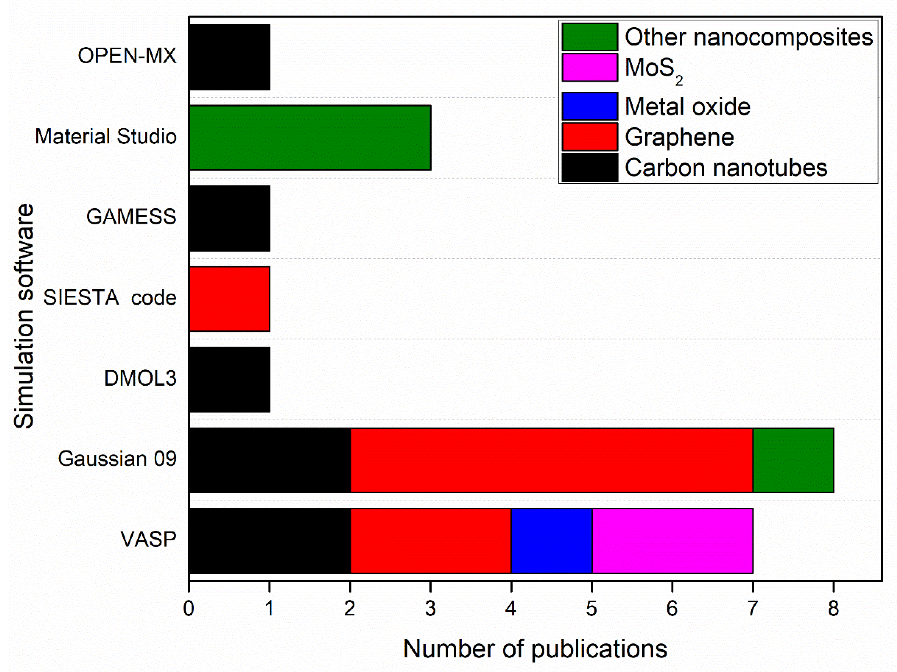
2.2. Simulation of Nanomembranes
| Membrane | Software | Simulation Method | ||
|---|---|---|---|---|
| O | ||||
| 9 | ||||
| ) | ||||
| Materials Studio | ||||
| DFT (PBE) | ||||
| Exchange-Correlation functional | ||||
| [ | ||||
| 38 | ||||
| ] | ||||
| MoS | ||||
| 2 | ||||
| nanosheets | ||||
| VASP | DFT (PAW) | Kohn-Sham equations | [ | 36] |
| SWCNTs | Gaussview | DFT (B3LYP5) functional | Exchange-Correlation functional | [21] |
| CF/BiOBr/Ag3PO4 cloth | Materials Studio | DFT (GGA-PBE) | Exchange-Correlation functional | [39] |
3. Nanocomposites
3.1. Synthesis of Nanocomposites
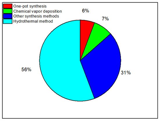
The Hydrothermal Method
| Nanocomposite Material | Material Type | Reference |
|---|---|---|
| Heterogeneous Fenton catalysts (CNTs/Fh) | Oxidized carbon nanotubes (CNTs), ferrihydrite (Fh) | [77] |
| (N-rGO/BiVO4) | Bismuth vanadate (BiVO4), reduced graphene oxide (rGO), nitrogen (N) | [78] |
| ZnO@C | Zinc Oxide (ZnO), carbon (C) | [79] |
| Cerium zirconium oxide (CexZryO2) | Cerium (Ce), zirconium oxide (ZrO2) | [80] |
| ZnO/Al2O3 | Zinc oxide (ZnO), aluminium oxide (Al2O3). | [81] |
| C, N, F/TiO2NTs |
| Nanocomposite Material | Material Type | Reference |
|---|---|---|
| Co3O4/CNTs | Carbon nanotubes (CNTs), cobalt tetra-oxide (Co3O4) | [116] |
| O-CNTs, G-CNTs | Oxidized carbon nanotubes (O-CNTs), graphitized carbon nanotubes (G-CNTs). | [48] |
| Vertically aligned (VA) CNT (open-end) hybrid membrane | Carbon nanotube (CNT), polydimethylsiloxane (PDMS) membrane |
[49] |
| COOH/CNTs | Carbon nanotubes (CNTs), carboxylic functionalized groups (COOH) | [117] |
| Carbon (C), nitrogen (N), fluoride (F), titanium dioxide nanotubes (TiO | 2NTs) | [82] |
| iN-Ti3C2/TiO2 hybrid | Titanium carbide (Ti3C2), titanium dioxide (TiO2), isopropyl amine, nitrogen (N) | [83] |
| TiO2 nanoflowers (TNFs) |
Titanium dioxide (TiO2) | [84] |
| Titanate nanotubes supported TiO2 (TiO2/TiNTs) | Titanium dioxide (TiO2), titanate nanotubes | [85] |
| Black phosphorus quantum dots/Tubular g-C3N4 (BPQDs/TCN) |
Black phosphorus (BP), tubular g-C3N4 | [86] |
| Sodium titanate nanotubes (Na-TNT) | Sodium (Na), titanate nanotubes (TNT) | [87] |
| Fe2O3-PC nanohybrids | Iron oxide (Fe2O3) | [88] |
| NiO nanobelt | Nickel oxide (NiO) | [89] |
| Carbon dots/g-C3N4 (C-CN) heterostructures | Graphitic Carbon Nitride (g-C3N4) | [90] |
| AgBr/h-MoO3 | Silver bromide (AgBr), hexagonal molybdenum oxide (h-MoO3) | [91] |
| Hybrid catalysts (CN-CGs) | Coal gangue (CG), graphitic carbon nitride g-C3N4 (CN) |
[92] |
| N-doped BiVO4 | Nitrogen (N), bismuth vanadate (BiVO4) | [93] |
| PPECu thin film electrode | Copper (Cu), phenylacetylene (PPE) | [94] |
| FexMo1-xS2 catalysts | Iron (Fe), Molybdenum disulfide (MoS2) | [95] |
| P-doped porous g-C3N4 | Graphitic carbon nitride (g-C3N4), phosphorus (P) | [96] |
| 1D/2D W18O49/g-C3N4 nanocomposites | Graphitic carbon nitride (g-C3N4), oxygen-deficient tungsten oxide (W18O49) |
[97] |
| Oct-Cu2O NCs | Cuprous oxide (Cu2O) | [98] |
| g-C3N4 | Graphitic carbon nitride (g-C3N4) | [99] |
| ZIF8@carbon nanotube | Carbon nanotube (CNT), zeolitic imidazole framework-8 (ZIF8) | [51] |
| CNF/LDH | Carbonaceous nanofiber (CNF), nickel (Ni), aluminium (Al) | [52] |
| PVP/MoS2 | Molybdenum disulphide, polyvinylpyrrolidone | [100] |
| β-CD/TiO2 | Titanium dioxide (TiO2), β-cyclodextrin C42H70O35 | [101] |
| MOF-545 | Zirconyl chloride octahydrate, Sigma-Aldrich; porphyrin, H4-Tcpp-H2, TCl | [102] |
Chemical Vapor Deposition
References
- Deng, Y.; Wu, Y.; Chen, G.; Zheng, X.; Dai, M.; Peng, C. Metal-organic framework membranes: Recent development in the synthesis strategies and their application in oil-water separation. Chem. Eng. J. 2021, 405, 127004.
- Jakšić, Z.; Jakšić, O. Biomimetic nanomembranes: An overview. Biomimetics 2020, 5, 24.
- Nosheen, S. Nanomembrane applications in environmental engineering. In Nanotechnology Applications in Environmental Engineering; IGI Global: Hershey, PA, USA, 2019; pp. 103–120.
- Jani, A.M.; Anglin, E.J.; McInnes, S.J.P.; Losic, D.; Shapter, J.G.; Voelcker, N.H. Nanoporous anodic aluminium oxide membranes with layered surface chemistry. Chem. Commun. 2009, 21, 3062–3064.
- Mei, Y.; Thurmer, D.J.; Deneke, C.; Kiravittaya, S.; Chen, Y.-F.; Dadgar, A.; Bertram, F.; Bastek, B.; Krost, A.; Christen, J.; et al. Fabrication, self-assembly, and properties of ultrathin AlN/GaN porous crystalline nanomembranes: Tubes, spirals, and curved sheets. Acs Nano 2009, 3, 1663–1668.
- De Wolf, I.; Senez, V.; Balboni, R.; Armigliato, A.; Frabboni, S.; Cedola, A.; Lagomarsino, S. Techniques for mechanical strain analysis in sub-micrometer structures: TEM/CBED, micro-Raman spectroscopy, X-ray micro-diffraction and modeling. Microelectron. Eng. 2003, 4, 425–435.
- Dhanabal, R.; Naveena, D.; Velmathi, S.; Bose, A.C. Reduced graphene oxide supported molybdenum oxide hybrid nanocomposites: High performance electrode material for supercapacitor and photocatalytic applications. J. Nanosci. Nanotechnol. 2020, 20, 4035–4046.
- Agboola, O.; Sadiku, E.R.; Mokrani, T. Nanomembrane materials based on polymer blends. In Design and Applications of Nanostructured Polymer Blends and Nanocomposite Systems; William Andrew Publishing: Norwich, NY, USA, 2016; pp. 101–123.
- Won, Y.-J.; Lee, J.; Choi, D.-C.; Chae, H.R.; Kim, I.; Lee, C.-H.; Kim, I.-C. Preparation and application of patterned membranes for wastewater treatment. Environ. Sci. Technol. 2012, 46, 11021–11027.
- Pérez-Madrigal, M.M.; Armelin, E.; Puiggalí, J.; Alemán, C. Insulating and semiconducting polymeric free-standing nanomembranes with biomedical applications. J. Mater. Chem. B 2015, 3, 5904–5932.
- Lu, P.; Chen, W.; Zhu, M.; Murray, S. Embedding lauric acid into polystyrene nanofibers to make high-capacity membranes for efficient thermal energy storage. ACS Sustain. Chem. Eng. 2017, 5, 7249–7259.
- Saleh, T.A. Protocols for synthesis of nanomaterials, polymers, and green materials as adsorbents for water treatment technologies. Environ. Technol. Innov. 2021, 24, 101821.
- Gracheva, I.E.; Moshnikov, V.; Maraeva, E.; Karpova, S.S.; Alexsandrova, O.A.; Alekseyev, N.I.; Kuznetsov, V.V.; Olchowik, G.; Semenov, K.; Startseva, A.V.; et al. Nanostructured materials obtained under conditions of hierarchical self-assembly and modified by derivative forms of fullerenes. J. Non-Cryst. Solids 2012, 358, 433–439.
- Chen, J.; Yao, B.; Li, C.; Shi, G. An improved Hummers method for eco-friendly synthesis of graphene oxide. Carbon 2013, 64, 225–229.
- Yahaya, N.Z.S.; Paiman, S.H.; Abdullah, N.; Mahpoz, N.M.; Raffi, A.A.; Rahman, M.A.; Abas, K.H.; Aziz, A.A.; Othman, M.H.D.; Jaafar, J. Synthesis and characterizations of MIL-140B-Al2O3/YSZ ceramic membrane using solvothermal method for seawater desalination. J. Aust. Ceram. Soc. 2020, 56, 291–300.
- Maina, J.W.; Gonzalo, C.P.; Merenda, A.; Kong, L.; Schütz, J.A.; Dumée, L.F. The growth of high density network of MOF nano-crystals across macroporous metal substrates–Solvothermal synthesis versus rapid thermal deposition. Appl. Surf. Sci. 2018, 427, 401–408.
- Ahn, E.; Gaiji, H.; Kim, T.; Abderrabba, M.; Lee, H.-W.; Kim, B.-S. Graphene oxide nanosheet as a two-dimensional polyelectrolyte: pH-responsive behavior of a multilayered nanomembrane. J. Membr. Sci. 2019, 585, 191–198.
- Kohn, J. Small-scale membrane filter electrophoresis and immuno-electrophoresis. Clin. Chim. Acta 1958, 3, 450–454.
- Lagashetty, A.; Havanoor, V.; Basavaraja, S.; Balaji, S.D.; Venkataraman, A. Microwave-assisted route for synthesis of nanosized metal oxides. Sci. Technol. Adv. Mater. 2007, 8, 484.
- Dahiya, M.S.; Tomer, V.K.; Duhan, S. Metal–ferrite nanocomposites for targeted drug delivery. In Applications of Nanocomposite Materials in Drug Delivery; Woodhead Publishing: Sawston, UK, 2018; pp. 737–760.
- Al-Hamadani, Y.A.; Jung, C.; Im, J.-K.; Boateng, L.K.; Flora, J.R.; Jang, M.; Heo, J.; Park, C.M.; Yoon, Y. Sonocatalytic degradation coupled with single-walled carbon nanotubes for removal of ibuprofen and sulfamethoxazole. Chem. Eng. Sci. 2017, 162, 300–308.
- de Oliveira, P.V.; Zanella, I.; Bulhoes, L.O.S.; Fagan, S.B. Adsorption of 17 β-estradiol in graphene oxide through the competing methanol co-solvent: Experimental and computational analysis. J. Mol. Liq. 2021, 321, 114738.
- Abdulkhair, B.; Salih, M.; Modwi, A.; Adam, F.; Elamin, N.; Seydou, M.; Rahali, S. Adsorption behavior of barium ions onto ZnO surfaces: Experiments associated with DFT calculations. J. Mol. Struct. 2021, 1223, 128991.
- Hu, Y.; Zhao, C.; Yin, L.; Wen, T.; Yang, Y.; Ai, Y.; Wang, X. Combining batch technique with theoretical calculation studies to analyze the highly efficient enrichment of U(VI) and Eu(III) on magnetic MnFe2O4 nanocubes. Chem. Eng. J. 2018, 349, 347–357.
- Tian, Y.L.; Hua, H.L.; Yue, W.W.; Chen, M.N.; Hu, G.C.; Ren, J.F.; Yuan, X.B. Adsorption properties of chloroform molecule on graphene: Experimental and first-principles calculations. Mod. Phys. Lett. B 2017, 31, 1750335.
- Kang, W.; Cui, Y.; Yang, Y.; Zhao, Z.; Wang, X.; Liu, X. An acid induction strategy to construct an ultralight and durable amino-functionalized graphene oxide aerogel for enhanced quinoline pollutants extraction from coking wastewater. Chem. Eng. J. 2021, 412, 128686.
- Hao, J.; Zhang, Q.; Liu, Y.; Chen, P.; Zheng, X.; Zhuang, X.; Fu, D.; Liu, H.; Liu, G.; Lv, W. A novel nitrogen-containing covalent organic framework adsorbent for the efficient removal of bisphenol A from aqueous solution. J. Taiwan Inst. Chem. Eng. 2020, 113, 204–213.
- Khajouei, M.; Najafi, M.; Jafari, S.A. Development of ultrafiltration membrane via in-situ grafting of nano-GO/PSF with anti-biofouling properties. Chem. Eng. Res. Des. 2019, 142, 34–43.
- Han, J.; Lee, S.; Choi, K.; Kim, J.; Ha, D.; Lee, C.-G.; An, B.; Lee, S.-H.; Mizuseki, H.; Choi, J.-W.; et al. Effect of nitrogen doping on titanium carbonitride-derived adsorbents used for arsenic removal. J. Hazard. Mater. 2016, 302, 375–385.
- Reynosa-Martínez, A.C.G.; Tovar, N.; Gallegos, W.R.; Rodríguez-Meléndez, H.; Torres-Cadena, R.; Mondragón-Solórzano, G.; Barroso-Flores, J.; Alvarez-Lemus, M.A.; Montalvo, V.G.; López-Honorato, E. Effect of the degree of oxidation of graphene oxide on As(III) adsorption. J. Hazard. Mater. 2020, 384, 121440.
- Zhang, L.; Hu, X.; Zhou, Q. Sunlight-assisted tailoring of surface nanostructures on single-layer graphene nanosheets for highly efficient cation capture and high-flux desalination. Carbon 2020, 161, 674–684.
- Lawal, I.A.; Lawal, M.M.; Akpotu, S.O.; Azeez, M.A.; Ndungu, P.; Moodley, B. Theoretical and experimental adsorption studies of sulfamethoxazole and ketoprofen on synthesized ionic liquids modified CNTs. Ecotoxicol. Environ. Saf. 2018, 161, 542–552.
- Chen, Y.; Zhang, W.; Yang, S.; Hobiny, A.; Alsaedi, A.; Wang, X. Understanding the adsorption mechanism of Ni(II) on graphene oxides by batch experiments and density functional theory studies. Sci. China Chem. 2016, 59, 412–419.
- Zhang, J.; Lu, X.; Shi, C.; Yan, B.; Gong, L.; Chen, J.; Xiang, L.; Xu, H.; Liu, Q.; Zeng, H. Unraveling the molecular interaction mechanism between graphene oxide and aromatic organic compounds with implications on wastewater treatment. Chem. Eng. J. 2019, 358, 842–849.
- Liu, Y.; Fang, C.; Zhong, W.; Wei, Q.; Wang, Y.; Dai, Y.; Wang, Y.; Zhang, Z.; Liu, Y. Effective adsorption of uranyl ions with different MoS2-exposed surfaces in aqueous solution. Surf. Interfaces 2020, 18, 100409.
- Zhang, L.; He, X.; Zhou, Q.; Hu, X. Fabrication of 1T-MoS2 nanosheets and the high-efficiency removal of toxic metals in aquatic systems: Performance and mechanisms. Chem. Eng. J. 2020, 386, 123996.
- Younes, H.A.; Khaled, R.; Mahmoud, H.M.; Nassar, H.F.; Abdelrahman, M.M.; El-Ela, F.I.A.; Taha, M. Computational and experimental studies on the efficient removal of diclofenac from water using ZnFe-layered double hydroxide as an environmentally benign absorbent. J. Taiwan Inst. Chem. Eng. 2019, 102, 297–311.
- Huang, L.; Yang, Z.; Lei, D.; Liu, F.; He, Y.; Wang, H.; Luo, J. Experimental and modeling studies for adsorbing different species of fluoride using lanthanum-aluminum perovskite. Chemosphere 2021, 263, 128089.
- Shi, Z.; Zhang, Y.; Liu, T.; Cao, W.; Zhang, L.; Li, M.; Chen, Z. Synthesis of BiOBr/Ag3PO4 heterojunctions on carbon-fiber cloth as filter-membrane-shaped photocatalyst for treating the flowing antibiotic wastewater. J. Colloid Interface Sci. 2020, 575, 183–193.
- Neugebauer, J.; Hickel, T. Density functional theory in materials science. Wiley Interdiscip. Rev. Comput. Mol. Sci. 2013, 3, 438–448.
- Sharma, S.; Kumar, P.; Chandra, R. Applications of BIOVIA materials studio, LAMMPS, and GROMACS in various fields of science and engineering. In Molecular Dynamics Simulation of Nanocomposites Using BIOVIA Materials Studio, Lammps and Gromacs; Elsevier: Amsterdam, The Netherlands, 2019; pp. 329–341.
- Robinson, S. Simulation: The Practice of Model Development and Use; Wiley: Chichester, UK, 2004; Volume 50.
- Krogel, J.T. Nexus: A modular workflow management system for quantum simulation codes. Comput. Phys. Commun. 2016, 198, 154–168.
- Fan, Z.; Zhang, W.-B.; Tang, B.-Y. Electronic structures and elastic properties of monolayer and bilayer transition metal dichalcogenides MX2 (M = Mo, W; X = O, S, Se, Te): A comparative first-principles study. Chin. Phys. B 2015, 24, 097103.
- Lehner, A.J.; Fabini, D.H.; Evans, H.A.; Hébert, C.-A.; Smock, S.R.; Hu, J.; Wang, H.; Zwanziger, J.W.; Chabinyc, M.L.; Seshadri, R. Crystal and electronic structures of complex bismuth iodides A3Bi2I9 (A = K, Rb, Cs) related to perovskite: Aiding the rational design of photovoltaics. Chem. Mater. 2015, 27, 7137–7148.
- Lindsay, L.; Li, W.; Carrete, J.; Mingo, N.; Broido, D.A.; Reinecke, T.L. Phonon thermal transport in strained and unstrained graphene from first principles. Phys. Rev. B 2014, 89, 155426.
- Repetsky, S.P.; Vyshyvana, I.G.; Kruchinin, S.P.; Melnyk, R.M.; Polishchuk, A.P. The energy spectrum and the electrical conductivity of graphene with substitution impurity. arXiv 2020, arXiv:2003.02084v1.
- Zhang, J.; Li, T.; Li, X.; Liu, Y.; Li, N.; Wang, Y.; Li, X. A key role of inner-cation-π interaction in adsorption of Pb(II) on carbon nanotubes: Experimental and DFT studies. J. Hazard. Mater. 2021, 412, 125187.
- Yang, D.; Tian, D.; Cheng, C.; Liu, Y.; Zhao, Z.; Liu, Y.; Bao, Y.; Xue, C. Carbon nanotube arrays hybrid membrane with excellent separation performance and conductivity. J. Membr. Sci. 2021, 620, 118874.
- Ren, X.; Feng, J.; Si, P.; Zhang, L.; Lou, J.; Ci, L. Enhanced heterogeneous activation of peroxydisulfate by S, N co-doped graphene via controlling S, N functionalization for the catalytic decolorization of dyes in water. Chemosphere 2018, 210, 120–128.
- Wang, Y.; Zhao, W.; Qi, Z.; Zhang, L.; Peng, Y. Phosphate removal by MWCNT hybrids in presence of effluent organic matter: Adsorbent structure, wastewater quality, and DFT analysis. Sci. Total Environ. 2020, 745, 141054.
- Yu, S.; Liu, Y.; Ai, Y.; Wang, X.; Zhang, R.; Chen, Z.; Chen, Z.; Zhao, G.; Wang, X. Rational design of carbonaceous nanofiber/Ni-Al layered double hydroxide nanocomposites for high-efficiency removal of heavy metals from aqueous solutions. Environ. Pollut. 2018, 242, 1–11.
- Joseph, L.; Boateng, L.K.; Flora, J.R.; Park, Y.-G.; Son, A.; Badawy, M.; Yoon, Y. Removal of bisphenol A and 17α-ethinyl estradiol by combined coagulation and adsorption using carbon nanomaterials and powdered activated carbon. Sep. Purif. Technol. 2013, 107, 37–47.
- Zhang, S.; Sun, G.; He, Y.; Fu, R.; Gu, Y.; Chen, S. Preparation, characterization, and electrochromic properties of nanocellulose-based polyaniline nanocomposite films. ACS Appl. Mater. Interfaces 2017, 9, 16426–16434.
- Malhotra, B.D.; Ali, A. Nanomaterials in biosensors: Fundamentals and applications. In Nanomaterials for Biosensors; Elsevier: Amsterdam, The Netherlands, 2018; pp. 1–74.
- Chen, Y.; Lai, Z.; Zhang, X.; Fan, Z.; He, Q.; Tan, C.; Zhang, H. Phase engineering of nanomaterials. Nat. Rev. Chem. 2020, 4, 243–256.
- Chkirida, S.; Zari, N.; El Kacem Qaiss, A.; Bouhfid, R. Nanocomposite materials based on TiO2/clay for wastewater treatment. In Advanced Research in Nanosciences for Water Technology; Springer: Cham, Switzerland, 2019; pp. 363–380.
- Wang, J.; Li, Y.; Zheng, D.; Mikulčić, H.; Vujanović, M.; Sundén, B. Preparation and thermophysical property analysis of nanocomposite phase change materials for energy storage. Renew. Sustain. Energy Rev. 2021, 151, 111541.
- Jacob, J.; Haponiuk, J.T.; Thomas, S.; Gopi, S. Biopolymer based nanomaterials in drug delivery systems: A review. Mater. Today Chem. 2018, 9, 43–55.
- Hasnain, M.S.; Nayak, A.K. Nanocomposites for improved orthopedic and bone tissue engineering applications. In Applications of Nanocomposite Materials in Orthopedics; Woodhead Publishing: Sawston, UK, 2019; pp. 145–177.
- Singh, S.; Kumar, V.; Romero, R.; Sharma, K.; Singh, J. Applications of nanoparticles in wastewater treatment. In Nanobiotechnology in Bioformulations; Springer: Cham, Switzerland, 2019; pp. 395–418.
- Karn, B.; Kuiken, T.; Otto, M. Nanotechnology and in situ remediation: A review of the benefits and potential risks. Environ. Health Perspect. 2009, 117, 1813–1831.
- Zhang, S.; Qian, L.; Zhao, Q.; Wang, Z.; Lin, D.; Liu, W.; Chen, Y.; Zhang, J. Carbon nanotube: Controlled synthesis determines its future. Sci. China Mater. 2020, 63, 16–34.
- Rane, A.V.; Kanny, K.; Abitha, V.K.; Thomas, S. Methods for synthesis of nanoparticles and fabrication of nanocomposites. In Synthesis of Inorganic Nanomaterials; Woodhead Publishing: Sawston, UK, 2018; pp. 121–139.
- Manawi, Y.M.; Samara, A.; Al-Ansari, T.; Atieh, M.A. A review of carbon nanomaterials’ synthesis via the chemical vapor deposition (CVD) method. Materials 2018, 11, 822.
- Zhong, Q.; Cao, M.; Hu, H.; Yang, D.; Chen, M.; Li, P.; Wu, L.; Zhang, Q. One-pot synthesis of highly stable CsPbBr3@ SiO2 core–shell nanoparticles. Acs Nano 2018, 12, 8579–8587.
- Gan, Y.X.; Jayatissa, A.H.; Yu, Z.; Chen, X.; Li, M. Hydrothermal synthesis of nanomaterials. J. Nanomater. 2020, 2020, 8917013.
- Kaflé, B.P. Chemical Analysis and Material Characterization by Spectrophotometry; Elsevier: Amsterdam, The Netherlands, 2019.
- Adeniji, Q.A.; Odunaike, R.K.; Bamijoko, B.A.; Adeleke, A.T.; Dahunsi, K.T. Synthesis and characterization of Zinc Tin sulphide (ZTS) thin films via chemical bath deposition route. J. Appl. Sci. Inf. Comput. 2020, 1, 22–31.
- Yang, G.; Park, S.-J. Conventional and microwave hydrothermal synthesis and application of functional materials: A review. Materials 2019, 12, 1177.
- Li, M.; Magdassi, S.; Gao, Y.; Long, Y. Hydrothermal synthesis of VO2 polymorphs: Advantages, challenges and prospects for the application of energy efficient smart windows. Small 2017, 13, 1701147.
- Wu, Y.Z.; Chen, M.; Yan, X.H.; Ren, J.; Dai, Y.; Wang, J.J.; Pan, J.M.; Wang, Y.P.; Cheng, X.N. Hydrothermal synthesis of Fe3O4 nanorods/graphitic C3N4 composite with enhanced supercapacitive performance. Mater. Lett. 2017, 198, 114–117.
- Modan, E.M.; Plăiașu, A.G. Advantages and disadvantages of chemical methods in the elaboration of nanomaterials. Ann. “Dunarea de Jos” Univ. Galati. Fascicle IX Met. Mater. Sci. 2020, 43, 53–60.
- Das, S.; Dhara, S. Chemical solution synthesis for materials design and thin film device applications. In Chemical Solution Synthesis for Materials Design and Thin Film Device Applications; Elsevier: Amsterdam, The Netherlands, 2021.
- Yang, G.; Xie, J.; Deng, Y.; Bian, Y.; Hong, F. Hydrothermal synthesis of bacterial cellulose/AgNPs composite: A “green” route for antibacterial application. Carbohydr. Polym. 2012, 87, 2482–2487.
- Byrappa, K.; Yoshimura, M. Handbook of Hydrothermal Technology; William Andrew: Norwich, NY, USA, 2012.
- Zhu, R.; Zhu, Y.; Xian, H.; Yan, L.; Fu, H.; Zhu, G.; Xi, Y.; Zhu, J.; He, H. CNTs/ferrihydrite as a highly efficient heterogeneous Fenton catalyst for the degradation of bisphenol A: The important role of CNTs in accelerating Fe(III)/Fe(II) cycling. Appl. Catal. B Environ. 2020, 270, 118891.
- Wang, X.L.; Li, J.; Liu, W.M. Synthesizing pyridinic-N dominate-doped graphene/BiVO4 nanocomposite as a superior photocatalyst for degradation under visible-irradiation. Opt. Mater. 2021, 114, 110922.
- Yang, C.; Wang, X.; Ji, Y.; Ma, T.; Zhang, F.; Wang, Y.; Ci, M.; Chen, D.; Jiang, A.; Wang, W. Photocatalytic degradation of methylene blue with C nanocomposites: Kinetics, mechanism, and the inhibition effect on monoamine oxidase A and B. NanoImpact 2019, 15, 100174.
- Li, P.; Guo, M.; Wang, Q.; Li, Z.; Wang, C.; Chen, N.; Wang, C.-C.; Wan, C.; Chen, S. Controllable synthesis of cerium zirconium oxide nanocomposites and their application for photocatalytic degradation of sulfonamides. Appl. Catal. B Environ. 2019, 259, 118107.
- Nie, Q.; Xie, Y.; Ma, J.; Wang, J.; Zhang, G. High piezo–catalytic activity of ZnO/Al2O3 nanosheets utilizing ultrasonic energy for wastewater treatment. J. Clean. Prod. 2020, 242, 118532.
- Wang, X.; Wang, L.L.; Guo, D.; Ma, L.L.; Zhu, B.L.; Wang, P.; Wang, G.C.; Zhang, S.M.; Huang, W.P. Fabrication and photocatalytic performance of C,N,F-tridoped TiO2 nanotubes. Catal. Today 2019, 327, 182–189.
- Ke, T.; Shen, S.; Rajavel, K.; Yang, K.; Lin, D. In situ growth of TiO2 nanoparticles on nitrogen-doped Ti3C2 with isopropyl amine toward enhanced photocatalytic activity. J. Hazard. Mater. 2021, 402, 124066.
- Zhao, Y.; Chi, Y.; Tian, C.; Liu, Y.; Li, H.; Wang, A. Recycling of titanium-coagulated algae-rich sludge for enhanced photocatalytic oxidation of phenolic contaminants through oxygen vacancy. Water Res. 2020, 177, 115789.
- Cheng, K.; Cai, Z.; Fu, J.; Sun, X.; Sun, W.; Chen, L.; Zhang, D.; Liu, W. Synergistic adsorption of Cu(II) and photocatalytic degradation of phenanthrene by a jaboticaba-like TiO2/titanate nanotube composite: An experimental and theoretical study. Chem. Eng. J. 2019, 358, 1155–1165.
- Wang, W.; Niu, Q.; Zeng, G.; Zhang, C.; Huang, D.; Shao, B.; Zhou, C.; Yang, Y.; Liu, Y.; Guo, H.; et al. 1D porous tubular g-C3N4 capture black phosphorus quantum dots as 1D/0D metal-free photocatalysts for oxytetracycline hydrochloride degradation and hexavalent chromium reduction. Appl. Catal. B Environ. 2020, 273, 119051.
- Saleh, R.; Zaki, A.H.; El-Ela, F.I.A.; Farghali, A.A.; Taha, M.; Mahmoud, R. Consecutive removal of heavy metals and dyes by a fascinating method using titanate nanotubes. J. Environ. Chem. Eng. 2021, 9, 104726.
- Maji, T.K.; Hasan, N.; Ghosh, S.; Wulferding, D.; Bhattacharya, C.; Lemmens, P.; Karmakar, D.; Pal, S.K. Development of a magnetic nanohybrid for multifunctional application: From immobile photocatalysis to efficient photoelectrochemical water splitting: A combined experimental and computational study. J. Photochem. Photobiol. A Chem. 2020, 397, 112575.
- Kitchamsetti, N.; Ramteke, M.S.; Rondiya, S.R.; Mulani, S.R.; Patil, M.S.; Cross, R.W.; Dzade, N.Y.; Devan, R.S. DFT and experimental investigations on the photocatalytic activities of NiO nanobelts for removal of organic pollutants. J. Alloys Compd. 2021, 855, 157337.
- Duan, Y.; Deng, L.; Shi, Z.; Liu, X.; Zeng, H.; Zhang, H.; Crittenden, J. Efficient sulfadiazine degradation via in-situ epitaxial grow of Graphitic Carbon Nitride (g-C3N4) on carbon dots heterostructures under visible light irradiation: Synthesis, mechanisms and toxicity evaluation. J. Colloid Interface Sci. 2020, 561, 696–707.
- Cai, Z.; Song, Y.; Jin, X.; Wang, C.-C.; Ji, H.; Liu, W.; Sun, X. Highly efficient AgBr/h-MoO3 with charge separation tuning for photocatalytic degradation of trimethoprim: Mechanism insight and toxicity assessment. Sci. Total Environ. 2021, 781, 146754.
- Zhang, X.; Zhao, R.; Zhang, N.; Su, Y.; Liu, Z.; Gao, R.; Du, C. Insight to unprecedented catalytic activity of double-nitrogen defective metal-free catalyst: Key role of coal gangue. Appl. Catal. B Environ. 2020, 263, 118316.
- Regmi, C.; Kshetri, Y.K.; Kim, T.-H.; Dhakal, D.; Lee, S.W. Mechanistic understanding of enhanced photocatalytic activity of N-doped BiVO4 towards degradation of ibuprofen: An experimental and theoretical approach. Mol. Catal. 2019, 470, 8–18.
- Wei, Z.; Hu, J.; Zhu, K.; Wei, W.; Ma, X.; Zhu, Y. Self-assembled polymer phenylethnylcopper nanowires for photoelectrochemical and photocatalytic performance under visible light. Appl. Catal. B Environ. 2018, 226, 616–623.
- Huang, L.-Z.; Wei, X.; Gao, E.; Zhang, C.; Hu, X.-M.; Chen, Y.; Liu, Z.; Finck, N.; Lützenkirchen, J.; Dionysiou, D. Single Fe atoms confined in two-dimensional MoS2 for sulfite activation: A biomimetic approach towards efficient radical generation. Appl. Catal. B Environ. 2020, 268, 118459.
- Li, Z.; Chen, Q.; Lin, Q.; Chen, Y.; Liao, X.; Yu, H.; Yu, C. Three-dimensional P-doped porous g-C3N4 nanosheets as an efficient metal-free photocatalyst for visible-light photocatalytic degradation of Rhodamine B model pollutant. J. Taiwan Inst. Chem. Eng. 2020, 114, 249–262.
- Deng, Y.; Feng, C.; Tang, L.; Zhou, Y.; Chen, Z.; Feng, H.; Wang, J.; Yu, J.; Liu, Y. Ultrathin low dimensional heterostructure composites with superior photocatalytic activity: Insight into the multichannel charge transfer mechanism. Chem. Eng. J. 2020, 393, 124718.
- Wang, P.; Tian, Y.; Wang, H.; Zhang, J.; Kong, L.; Zuo, W.; Li, D.; Yin, L. Strong adsorption of tetracycline on octahedral Cu2O nanocrystals exposed with facets: Adsorption behavior and mechanism insight. Appl. Surf. Sci. 2021, 542, 148545.
- Zhang, C.; Liu, Y.; Li, X.; Chen, H.; Wen, T.; Jiang, Z.; Ai, Y.; Sun, Y.; Hayat, T.; Wang, X. Highly uranium elimination by crab shells-derived porous graphitic carbon nitride: Batch, EXAFS and theoretical calculations. Chem. Eng. J. 2018, 346, 406–415.
- Gu, P.; Zhao, C.; Wen, T.; Ai, Y.; Zhang, S.; Chen, W.; Wang, J.; Hu, B.; Wang, X. Highly U(VI) immobilization on polyvinyl pyrrolidine intercalated molybdenum disulfide: Experimental and computational studies. Chem. Eng. J. 2019, 359, 1563–1572.
- Wang, J.; Zhang, R.; Lu, Z.; Ai, Y. Experimental and theoretical studies of spherical β-cyclodextrin modified titanium dioxide composites for uranium removal. Ecol. Eng. 2020, 149, 105835.
- Tokalıoğlu, Ş.; Yavuz, E.; Demir, S.; Patat, Ş. Zirconium-based highly porous metal-organic framework (MOF-545) as an efficient adsorbent for vortex assisted-solid phase extraction of lead from cereal, beverage and water samples. Food Chem. 2017, 237, 707–715.
- Senapati, S.; Maiti, P. Emerging bio-applications of two-dimensional nanoheterostructure materials. In 2D Nanoscale Heterostructured Materials; Elsevier: Amsterdam, The Netherlands, 2020; pp. 243–255.
- Carlsson, J.-O.; Martin, P.M. Chemical vapor deposition. In Handbook of Deposition Technologies for Films and Coatings; William Andrew Publishing: Norwich, NY, USA, 2010; pp. 314–363.
- Badv, M.; Jaffer, I.H.; Weitz, J.I.; Didar, T.F. An omniphobic lubricant-infused coating produced by chemical vapor deposition of hydrophobic organosilanes attenuates clotting on catheter surfaces. Sci. Rep. 2017, 7, 11639.
- Zhang, Y.; Zhang, L.; Zhou, C. Review of chemical vapor deposition of graphene and related applications. Acc. Chem. Res. 2013, 46, 2329–2339.
- Pourmand, S.; Abdouss, M.; Rashidi, A. Fabrication of nanoporous graphene by chemical vapor deposition (CVD) and its application in oil spill removal as a recyclable nanosorbent. J. Ind. Eng. Chem. 2015, 22, 8–18.
- Creighton, J.R.; Ho, P. Introduction to chemical vapor deposition (CVD). Chem. Vap. Depos. 2001, 2, 1–22.
- Haubner, R. The history of hard CVD coatings for tool applications at the University of Technology Vienna. Int. J. Refract. Met. Hard Mater. 2013, 41, 22–34.
- Tietjen, J.J. Chemical vapor deposition of electronic materials. Annu. Rev. Mater. Sci. 1973, 3, 317–326.
- Gao, L.; Ren, W.; Zhao, J.; Ma, L.-P.; Chen, Z.; Cheng, H.-M. Efficient growth of high-quality graphene films on Cu foils by ambient pressure chemical vapor deposition. Appl. Phys. Lett. 2010, 97, 183109.
- Park, H.J.; Meyer, J.; Roth, S.; Skákalová, V. Growth and properties of few-layer graphene prepared by chemical vapor deposition. Carbon 2010, 48, 1088–1094.
- Vasudev, M.C.; Anderson, K.D.; Bunning, T.J.; Tsukruk, V.V.; Naik, R.R. Exploration of plasma-enhanced chemical vapor deposition as a method for thin-film fabrication with biological applications. ACS Appl. Mater. Interfaces 2013, 5, 3983–3994.
- Cai, Z.; Liu, B.; Zou, X.; Cheng, H.-M. Chemical vapor deposition growth and applications of two-dimensional materials and their heterostructures. Chem. Rev. 2018, 118, 6091–6133.
- Cong, C.; Shang, J.; Wu, X.; Cao, B.; Peimyoo, N.; Qiu, C.; Sun, L.; Yu, T. Synthesis and optical properties of large-area single-crystalline 2D semiconductor WS2 monolayer from chemical vapor deposition. Adv. Opt. Mater. 2014, 2, 131–136.
- Liu, B.; Song, W.; Wu, H.; Liu, Z.; Teng, Y.; Sun, Y.; Xu, Y.; Zheng, H. Degradation of norfloxacin with peroxymonosulfate activated by nanoconfinement Co3O4@CNT nanocomposite. Chem. Eng. J. 2020, 398, 125498.
- Dastgerdi, Z.H.; Meshkat, S.S.; Esrafili, M.D. Enhanced adsorptive removal of Indigo carmine dye performance by functionalized carbon nanotubes based adsorbents from aqueous solution: Equilibrium, kinetic, and DFT study. J. Nanostruct. Chem. 2019, 9, 323–334.