Our present life is rather difficult to imagine without some facilities that ease our activities, such as computers and their applications, communication devices and, most of all, modern transportation. Their positive impact on our lives and psyches is considerable, but so are their “side effects”. Therefore, scientists search for solutions to indulge these negative effects, especially those with long-term consequences, such as the greenhouse effect on our planet. The main element responsible for this last issue is carbon dioxide, released in a significant amount by the transportation sector. Thus, automotive constructors are interested in producing vehicles with fewer emission propulsion systems, aside from improved performances. Even though there is an ascending trend in releasing electric or hybrid models for most car manufacturers, vehicles equipped with internal combustion engines will keep the top position in the market for many years.
One main direction in improving the efficiency of an internal combustion engine, together with lowering the emissions, is supercharging, i.e., creating a considerable amount of boost for the inlet combustion air. Turbochargers are the most commonly used for this task, but another advantageous alternative exploiting the energy within exhaust gases is the pressure wave supercharger (PWS).
Developed initially in the 1920s’ as a pressure exchanger, the PWS attracted the attention of car manufacturers, mostly during the 1980s’, entering afterwards in a shadow of contention. Lately, a renewed interest was shown by redesigning the classical geometry or by using pressure wave technology in other different applications.
2. General Performance of Pressure Wave Supercharger
The PWS achieves its capability by utilizing the dynamics of fluids similar to the turbine and the compressor of a turbocharger. However, the PWS boost value is not primarily dependent on the rotor rotational speed, as in the case of a turbocharger, but it is more related to the engine’s temperature ratio. In consequence, a high boost level can be achieved at low engine speeds, resulting in a beneficial effect on the engine torque back-up. Moreover, the response of the air higher pressure is extremely fast, thus eliminating the specific turbocharger lags
[1][2][11,12]. In addition, the pressure ratio of a turbocompressor is limited by its surge limit—thus, for high pressure ratios, turbochargers have to be connected in series—while the PWS does not have such a surge limit. This is another of its major advantages, together with its robust structure, erosion resistance and lower production costs compared to performant turbocompressors.
PW technology has some shortcomings, including noisy operation, low mass flow rate on the frontal area, problems induced by fatigue because of cyclical fluctuations in pressure
[2][12] and significant sensitivity on backpressure, as the backpressure heavily deteriorates the rotor scavenging process. Therefore, no large backpressure can be placed downstream of the PWS (such as mufflers, catalysts, filters).
The most popular type of a pressure wave supercharger is the Comprex, named by Seippel in 1940, from the link of words COMPRession and EXpansion, i.e., the wave processes occurring inside the device. Seippel’s first patent was a pressure wave exchanger containing a rotor with 30 axial channels, working at 6000 rpm speed, reaching a pressure ratio of 3:1 and a global efficiency of 69%
[3][15]. Despite expectations, the device was not further developed because of shortcomings revealed when testing on engine
[2][4][12,16].
However, this attempt outlined the idea of using a pressure wave rotor for charging engines. In 1949, the American company ITE Circuit Breaker Co. (Zurich, Switzerland) started tests on PWS for diesel engines, showing satisfactory results. Only in 1957, ITE started the tests on charging vehicles with the new “COMPREX”
[2][5][10,12]; even though it could not reach a sufficient boost at very low engine speeds
[4][16], it proved that this pressure wave exchanger can raise air pressure over a wide range of load values and speeds and it operates without any lag or smoke
[5][6][6,10]. A cooperative program, started in 1955, between ITE and BBC Brown Boveri & Co. (Zurich, Switzerland) continued the development of PWSs for diesel engines, succeeding to make cycle changes and to solve the previous deficiencies
[4][16].
The new Comprex was initially fitted to charge truck diesel engines for its major benefit: elimination of the turbocharger lag. For instance, M. Berchtold from ITE Circuit Breaker Co. (Zurich, Switzerland) reported in 1958
[5][10] the data obtained for a 4-stroke Caterpillar diesel engine supercharged with a Comprex (ITE patent), when the rotor speed was maintained constant at 5500 rpm and when the rotor speed was variated from 2340 to 7000 rpm, corresponding to an operating engine speed range of 400 to 1200 rpm. The brake mean effective pressure (bmep), used instead of torque, representing different constant exhaust gas temperatures and air manifold pressures, had a maximum of about 175 lbs/in
2 (12 bar) for 800 rpm for about all conditions, while the boost pressure varied from 14 to 40 in. of Hg (0.47 to 1.35 bar), the maximum obtained for the variable set of conditions.
In 1960, Berchtold and Gull
[7][17] reported results from experimental road tests of a White truck tractor Model 9000 equipped with a Cummins JT-6-B-20° engine supercharged with Comprex. The PWS had a rotor with 107 mm mean diameter, 140 mm external case diameter and a 95.5 cm
2 flow area. The Comprex drive ratio was 3.4:1, which was directly driven from the crankshaft. The performance was shown by plotting the air discharge volume as a function of air discharge pressure ratio p
air/p
0 for constant exhaust gas and air temperatures, constant air flow and constant pressure drop (air discharge to gas intake pressures) and Comprex speeds of 4000, 6000 and 8000 rpm. The operating points were set according to the maximum thermal load of the engine, i.e., maximum engine torque, obtained by setting the fuel flow to the maximum, using the Cummins fuel pump control system
[7][17]. The results specified at the sea level conditions are summarized in
Table 1.
Table 1. Experimental data when using Comprex with a 5.9 L Diesel engine (1960) [7]. Experimental data when using Comprex with a 5.9 L Diesel engine (1960) [17].
| Engine Speed/Comprex Speed [rpm] |
Max. BMEP [bar] |
Exhaust Gas/Air Intake Temperature [°C] |
Pressure Ratio pair/p0 |
Required Air Flow [m3/s] |
Air Flow [m3/s] at Density [kg/m3] |
| 2350/8000 |
9.5 |
650/170 |
2.03 |
0.128 |
0.125/1.60 |
| 1760/6000 |
11.4 |
] the performance parameters of a diesel engine naturally aspirated (NA) or supercharged with a turbocompressor (impeller diameter of approx. 100 mm) or a Comprex CX-180 charger (180 mm rotor diameter). The engine was a Saurer 4-stroke diesel engine with six cylinders and displacement of 11.15 l. The comparison showed a similar increase in the effective power output at high speeds (1400…2200 rpm) for turbo and Comprex superchargers (see
Table 2), but at low speeds, higher values were registered for the Comprex supercharging. The torque, represented as the mean effective pressure, is significantly different at low speeds and quite similar at high ones for turbo and Comprex. The study reports an increase in performance of 43% at maximum speed for both supercharging versions compared to the original NA engine, and, in terms of mean effective pressure, at low speeds, an increase of 67% when charging with Comprex compared to the NA engine, and 45% more torque compared to the turbo charging. Despite the higher mean pressure in this speed range, the Comprex supercharging achieves cleaner exhaust gas (lower smoke values according to Bosch gas sampling). In the upper speed range, the two chargers can be considered practically equivalent regarding the smoke values (
Table 2). Specific fuel consumption encounters a minimum of about 160 g/PSh (217.5 g/kWh) at 1300–1400 rpm, almost equivalent for both chargers, with an improvement in specific fuel consumption of up to 5% compared to the naturally aspirated variant
[9][19]. Because of the relatively large heat exchange between the fresh air drawn in and the Comprex’s cell wheel, the temperature of the charge air when using the Comprex is higher than when the turbocharger is used, varying for the CX from 125 °C to 165 °C and for TC from 50 °C to 135 °C. However, the air density delivered by the Comprex is higher than that of the turbocharger, with the highest difference being 24% at 1000…1200 rpm
[9][19].
Table 2. Comparative data when NA and when using Comprex or Turbo-compressor with a 11.1 L Diesel engine (1970) [9]. Comparative data when NA and when using Comprex or Turbo-compressor with a 11.1 L Diesel engine (1970) [19].
| Engine Performance |
Speed
[rpm] |
NA Engine |
Comprex |
Turbo |
| 677/163 |
| 2.10 |
0.097 |
0.095/1.68 |
| 1170/4000 |
10.5 |
620/121 |
1.62 |
0.065 |
0.065/1.44 |
In a joint development project (1961) between Brown, Boveri & Co. (Zurich, Switzerland) and ITE Circuit Breaker Co. (Zurich, Switzerland)
[8][18], PW charging was explored on a Saurer truck diesel engine with 95 hp, supercharged with a modified Comprex, designed for almost twice the engine power (185 hp) and adapted by tangential reduction of the openings towards the engine. The experiments aimed to optimize the Comprex process and the possibility of adaptation to smaller engines. The study shows that by reducing the stator high-pressure openings and using a rotor with a higher number of cells (49 instead of 35), the power could be matched to the smaller engine; also, the mean pressures of gasoline engines can be achieved and, with optimally adapted Comprex, the boost pressure can be increased at low engine speeds. They also proved that by using the simple and cheap Comprex, the small vehicle engine torque can be increased to that of gasoline engines of the same stroke volume, with very favorable fuel consumption
[8][18].
A comparative study performed in 1970 by Brown Boveri & Co. (Zurich, Switzerland) in cooperation with Adolph Saurer & Co. (Arbon, Switzerland) reported
[9][19
| Max. output power [hp] |
2200 |
210 |
295 |
290 |
| Effective power [hp] |
1100
1400 |
120
145 |
180
225 |
135
218 |
| Mean effective pressure [bar] |
1100
~1400 |
8.0
8.3 (max.) |
13.7 (max.)
13.3 |
10.3
13.0 (max.) |
| Boost pressure ratio |
1100
1400
2000
2200 |
-
-
-
- |
1.95
|
/h and a power range from 25 to 100 kW for passenger cars
[12][13][22,23]. The first 6 CX models ensure power outputs, as summarized in
Table 3 [12][22]. Later, the range was extended to CX-200 and the power output reached was 450 kW. The range CX-71, 78, 85, 93, 102 and 112 was mounted and tested on passenger cars, with a maximum of 2.2 supercharging ratio, a compression efficiency of 0.64…0.66 and overall efficiency of 0.45…0.47
[10][12][13][14][20,22,23,24]. The range CX-112, 125, 140, 160, 180 and 200 was tested on heavy duty vehicles, reaching a maximum supercharging ratio of 3.0, a compression efficiency of 0.66…0.7 and overall efficiency of 0.47…0.5
[10][20]. The smallest Comprex model was marked CX-65, designed exclusively for supercharging small displacement compression ignition engines of 0.5…0.8 L and CX-125 used for supercharging 3.0…3.5 L tractor engines
[2][15][12,25].
Table 3. Max. engine power charged with Comprex models, with or without air intake cooling (1980’s) [12]. Max. engine power charged with Comprex models, with or without air intake cooling (1980’s) [22].
| Comprex Model |
Power [kW]
(No CAC) |
Power [kW]
(With CAC) |
| CX-71 |
36 |
40 |
| CX-78 |
42 |
48 |
| CX-85 |
52 |
67 |
| 2.15 |
| 2.35 (max.) |
2.25 |
1.3
1.65
2.05
2.1 (max.) |
| Charge air temperature [°C] |
1400
2200 |
-
- |
138
165 |
85
135 |
| Specific fuel consumption [g/kWh] |
~1400 |
230 |
217 (min.) |
217 (min.) |
In 1978, a Diesel engine 2.1 L supercharged with Comprex was tested for the first time on a passenger car (Opel)
[10][20]. The engine registered an excellent response at low speeds and moderate gain in torque compared to the natural aspirated similar engines (bmep of 6 to 10 bar, the peak value registered at about 2800 rpm engine speed)
[10][20]. Comprex performance was affected by the pulsations of the exhaust gas pressure in the exhaust manifold; therefore, some geometry modifications were made, and the results were satisfactory: the bmep varied between 9 and 13 bar, with the maximum value at about 2200 rpm engine speed. In addition, the changes allowed reduction of the Comprex diameter from 112 to 93 mm, thus lowering the weight to about 60%. A supercharging pressure ratio of 1.4…1.5 was gained in the low speed range and a bmep of 12.5 bar was reported at the mean engine speed, double as the similar naturally aspirated engine. Near the maximum engine speed, the torque curve falls to 30…40%
[10][20].
Additionally, in the late 1970s, other car manufacturers focused their attention on implementing the Comprex to supercharge automobile engines; Brown, Boveri & Co fitted the Comprex on 50 Volkswagen cars, and Opel also charged 750 of their 2.3 L Senator model with Comprex CX-102
[11][21]. Later, in the 1980s, Mazda supercharged the 2.0 L diesel engine of model 626 with an improved Comprex, selling about 150,000 cars
[1][6][6,11].
PWS performance is influenced by the major losses that appear: leakage at the HPA and HPG ports, the energy still contained within the LPG, the drive power wasted on bearing friction and windage, and the negative angular momentum given by the air flow entering inclined into the axial channels
[5][10]. The early Comprex also had a number of shortcomings that were removed during years of research, such as limited operating range at start and idle working points, low compression efficiency, much EGR at idle and partial load, noise and costs (comparing to the turbocharger). The improvement meant: introduction of the pockets for detuning the reflecting waves, reduction of the axial clearances for increasing the compression efficiency, usage of new materials with low expansion characteristics for the rotor and better design of bearings, introduction of a second row of channels for lowering the noise, fitting the Comprex with the exhaust waste-gate (to reduce the pressure ratio when the engine needs a lower one than provided by the PWS) and with the inlet starting valves (to reduce exhaust gas recirculation that occurs at low pressure ratios
[1][11].
The COMPREX pressure wave supercharger was developed by Brown Bovery & Co. in 6 dimensional models, with similar geometry, named CX followed by a number indicating the rotor diameter, from CX-71 to CX-112, covering a range of engine’s swept volumes of 0.8…3.0 L, e.g., a volume flow of charge air from 0.037 to 0.115 m
[14][24] the results of investigations carried out two years on PWS supercharging automobile diesel engines. The results show that the exhaust gas pressure before PWS is slightly lower than the charging air pressure when accelerating between 0 to 30% of nominal speed and slightly higher between 30% and 100% of nominal speed, the charging air pressure attaining almost 90% of the maximum of the exhaust gas pressure. In the same study
[14][24], a comparison between mean effective pressures measured at different speeds for truck and automobile engines supercharged by a PWS highlights the very wide range of speeds for the automobile engine, with relatively low mep at constant specific fuel consumption.
Table 4 shows the peak values for the mean effective pressure for both applications. The same analysis
[14][24] investigates the torque of 3 different Opel engines supercharged with CX-112: a 2.1 L engine without CAC, a 2.3 L engine with CAC and a 3.0 L engine with CAC. The diagrams reveal that the swept volume of 3.0 L is the best match for the CX-112—the smallest Comprex used for trucks adapted for use on automobile engines. By supercharging, a peak value for bmep of 11.5 bar is reached for the 3.0 L engine and 10.8 bar for the 2.3 L (both at approx. 2200 rpm, where the bmep value is 9.5 bar for the 2.1 L engine), and a peak value for the 2.1 L engine of 10.1 bar is reached at approx. 2800 rpm. Moreover, cooling the charge air proved to be efficient in increasing the pressure ratio, thus improving the engine torque curve.
Table 4. Comparison between the two types of Comprex applications [14]. Comparison between the two types of Comprex applications [24].
Vehicle
CX Application |
MEP Peak Value [bar] |
| CX-93 |
| 62 |
70 |
| CX-102 |
71 |
82 |
| CX-112 |
90 |
100 |
Therefore, Comprex had the capabilities required by the vehicle Diesel engines, where changes of instant load and engine speed are significant. The PWS size has a rather small influence on thermal efficiency, as shown in
[12][14][22,24], experimentally proved on diesel engines with power outputs of 60 to 450 kW, the powerful ones on truck applications—CX-112 to CX-200.
Kollbrunner from Brown Boveri & Co. reported in 1981
| Speed [rpm] |
Sp. Fuel Consumption [g/kWh] |
| Heavy truck |
23 |
1000 |
210 |
| Passenger car |
11.5 |
2000 |
260 |
The processes within every cell are characterized as unsteady flow phenomena, the state changing function of the shockwave velocity—which is dependent on the sound speed—while the PWS’s charging pressure ratio is directly proportional to the mass flow and exhaust gas temperature. According to Zehnder and Mayer
[12][22], the PWS model CX-93 supercharging a 2.0 L diesel engine reaches an output maximum power of 70 kW when the charge air is cooled (CAC) and 62 kW without intake air cooling, as well as a pressure ratio at a full load of 2.7 when the exhaust gas temperature reaches 750 °C
[12][22]. Additionally, in their research, it can be observed that a maximum of 75% for the compression efficiency is attended in a narrow range for the volumetric flow, e.g., engine speed that goes below 60%. The density ratio, a measure for the supercharging ratio in the case of no air cooling, indicates that there is sufficient air for increasing performance, lower emissions and fuel consumption. When the variation is represented in the presence of the total compression efficiency as an iso-parameter, it can be seen that the performance can be improved when working near the full nominal engine speed and full load zone
[12][22].
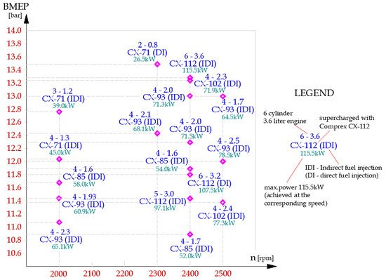
Charge air cooling (CAC) proved to be an optimal solution when the main purpose is to get maximum power of engine with low costs, as stated by Schruf and Kollbrunner
[13][23]. In their study on engines matched with Comprex from 1978 to 1983, with and without CAC, it was reported that, in the case of 60% cooler efficiency, the gain attained by the charge air density can be as much as 22% at half of the nominal engine speed and no less than 15% at higher speeds. Additionally, some features of the Comprex models in relation to the engines with which they were matched are summarized in
Figure 15 (peak values of bmep/engine speed; Direct/Indirect Injection, displacement, rated power).
Figure 15. Max. output power for 5 CX models and engine configurations (with CAC).
Max. output power for 5 CX models and engine configurations (with CAC). Made based on [23].
During the three decades, from the 1940s’ to 1970s’, there were preoccupations for developing, testing and improving rotor wave technology; theoretical and experimental studies were released on topics related to engine charging, but also to propulsion in the aviation industry, as reported in
[16][17][18][19][26,27,28,29].
In 1980, Ferrari experimented, for the next Formula 1 season, with the rescoped Maranello turbo engine, on a 312 T5 modified for the supercharged 1500 cc V6 engine
[20][30]. Ferrari understood that a supercharged engine could bring results and succeeded in winning the constructors’ titles in 1982 and 1983. However, the delay in the response of the acceleration pedal, due to the classic turbo lag made the engineers determined to try an alternative for the turbo, with an immediate response: the Comprex. Ferrari implemented the Comprex together with Brown Boveri Co. on the newborn model 126C, mostly to eliminate the turbo lag that was reported by the pilots to be “so annoying” when exiting the turns, especially on winding tracks such as Monte Carlo. For the Long Beach championship race in 81, Ferrari decided to use a double solution, traditional turbo and Comprex. The single-seater supercharged with Comprex was marked 126CX, and the turbocharged one was called 126CK. Unfortunately, during the tests, the driving rubber belts of the Comprex broke and Ferrari decided to return to the more reliable bi-turbosupercharging
[20][30].
Performance limitations were also discussed in the report about the Comprex superchargers presented at ONR/NAVAIR Wave Rotor Workshop 1985 by Prof. Berchtold
[10][20], comparing the Comprex application on heavy duty vehicles and passenger cars. Thus, the pressure ratio gain on trucks encountered values between 2.6 and 3.2 with the peak of 3.2 at 90% of engine speed, while for passenger car application, the pressure ratio varied between 2.0 and 2.2, with the peak at 80% of engine speed. A better solution for higher pressure ratios was suggested to be the two stages of supercharging: with Comprex for low pressure operation and turbocharger for high pressure stage, with the advantages of fast response and high efficiency in the high speed range
[10][20]. The tests were performed on a 6-cylinder Caterpillar engine with a modified compression ratio of 12. The pressure ratios for this two stage PWS/TC application vary between 3.2 and 5.8, with the peak at 90% of engine speed. The bmep in this configuration was reported to reach 27 bar for the peak value of the pressure ratio
[10][20].
The comparison made in the report
[10][20] about the Comprex also showed that the bmep for passenger car application gets to a peak of 13 bar when using an intercooler, or 11 bar without intercooling, while for the trucks engine application a maximum of 14.3 bar is reached, at about 60% of engine speed. A higher bmep is gained when using Comprex on heavy duty engine with intercooling, with a maximum of 20.5 bar at 60% of engine speed. The combination CX/TC on a heavy-duty truck engine leads to a bmep peak of 28 bar at 70% engine speed
[10][20].
In the late 1980’s, another step further was made by developing a “free running” Comprex, in a collaboration between Asea Brown Bovery ABB and NGK-Insulators, the rotor being made by ceramic material of sintered silicon nitride
[21][22][31,32]. The rotor was tested on a Mercedes-Benz 190D passenger car
[23][33]. The novelty of the free-running PWS lies in using the kinetic energy from the exhaust gases to drive freely the rotor, as it is lighter, e.g., reduced inertia due to the new material and slightly modified geometry. The main reported advantages of the new PWS were high efficiency, rapid response, compact design with freedom in placing the device easier next to the engine. The free-running PWS performance items, such as overall efficiency, compression efficiency and the pressure-ratio variation, can be seen in
[18][28], showing that the parameters of the belt-driven proportional Comprex can be achieved by the free-running PWS at operating points of higher speed, which is closer to the optimum PWS operational speed. This increases the compression efficiency with an acceptable loss in pressure ratio but with a gain in a better PWS operating in the speed range lower than its optimum value. Another improvement brought to the free-running charger was a smaller axial clearance that comes with an increase in the overall efficiency, lower fuel consumption, and a better transient response, mainly in the part-load range
[21][31]. In addition, as the rotor speed is no longer correlated to the engine speed, the pressure wave process within the cells is not related to the PWS speed, as in a normal turbocharger
[21][22][31,32]. The rpm range is reduced; therefore, it is easier to optimize the process within the rotor cells and the transient response to load changes at low engine speeds. The testing showed that at about 60% of the PWS nominal speed, the waste-gate valve starts to operate, and a maximum of 13.6 bar was reported for the engine’s bmep when working at about 2300 rpm
[21][22][31,32].
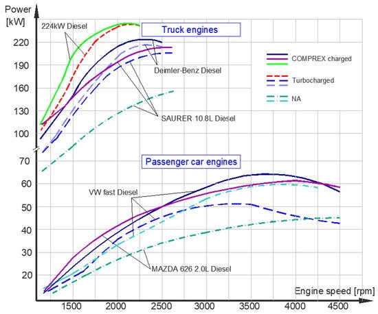
A comparative analysis between the performance parameters of engine chargers, i.e., mechanical supercharging using compressors (MC), turbochargers (TC) and pressure wave superchargers (PWS), compared to naturally aspirated engines (NA) emphasizes significant differences in terms of effective power, torque or specific fuel consumption. According to the reported results
[9][20][24][25][26][27][19,30,34,35,36,37] collated in
Figure 26, the PW supercharger registers higher effective power than the other types of chargers explained by the cooling effect of fresh air inside the channels, which keeps the heat losses reduced. The highest power of 64 kW was achieved for a Volkswagen fast diesel engine at about 3200 rpm and 61 kW for a Mazda 626 at about 4000 rpm. The supercharged Mazda 626 swirl-chamber diesel engine (2V OHC, with a compression ratio of 21.1:1) was developed from a former NA version by adding also the IDI technology—these improvements gave to this new model a driving performance comparable to the Mazda 2.0 L DOHC gasoline engine. Moreover, the maximum torque was 182 Nm at 2000 rpm and the fuel consumption was 265 g/kWh, 20% lower than the DOHC gasoline version
[20][30].
Figure 26. Comparative power output for passenger car engines and truck engines (upper diagrams)—(1984–1990).
Comparative power output for passenger car engines and truck engines (upper diagrams)—(1984–1990). Made based on [36,37].
PWS was used for charging truck engines as well, with good results in power, torque and fuel consumption compared to a turbocharger.
Figure 6 are also plotted these parameters for a 6-cylinder truck engine with a peak rated power of 224 kW
[20][30], for a Daimler-Benz diesel engine with a peak rated power of 222 kW and for a Saurer 10.8 L engine with a peak rated power of 210 kW
[9][24][26][27][19,34,36,37].
In 1990, Winterbone reported in
[1][11] a set of results of a Comprex supercharged engine of 1.6 L, showing the variation of engine bmep, compression efficiency and the overall efficiency, function of engine speed, with a maximum bmep of about 10.5 bar at 2500 rpm, a compression efficiency of 70% and total efficiency with a maximum of 40%, whereas pressure ratio achieved was 2:1.
In the 1990’s, when Comprex PWS was installed and sold on Ford Telstar and on three Mazda models: Capella Sedan, Capella Cargo and Capella CG (in the Japanese market around 25,000 units), PW technology proved its benefits
[24][34]. The engines supercharged with Comprex were slightly modified than the NA engine from 1983 in order to get higher strength and reliability, with high supercharging pressure ratios on a wide range of motor speeds.
Another project of the 1990’s, developed for GreenPeace by Swissauto WENKO AG in cooperation with BRM Design and Esoro, called SmILE (Small, Intelligent, Light and Efficient), had its main target the reduction of fuel consumption at half of the series production car Renault Twingo, maintaining its performance, capacity of transport, comfort and safety
[2][12]. The result was the first homologated car that registered 2.3…2.5 L/100 km fuel consumption in real traffic conditions (3.4 L/100 km for NEDC)
[28][38]. Later, the SmILE car, with a lowered overall weight, by 150 kg, was equipped with the SAVE gasoline engine, a new concept engine of 360 cc
[29][39], supercharged with a pressure wave supercharger (after 6 years of attempts to use conventional supercharging equipment), that attained, for emissions, values under EURO III standard. Optimizing the SAVE concept engine meant the control of the engine’s load by providing a throttling valve, the operation control at high loads by including gas pockets and a controlling valve for the PWS, and the adjustment of the PWS pressure ratio by using a waste-gate valve. In addition, the PWS operation was improved in terms of noise level and better compression efficiency for a wide range of speeds
[29][39]. After demonstrating its success with the Greenpeace project, Twingo SmILE, Swissauto WENKO AG worked for 10 more years, starting in 1998 (when took over both the premises and the rights for the PWS), to improve the initial concept, and in 2008 released the demonstrator car Volkswagen Golf 5, with a 1.0 Liters engine and supercharged with the new generation of PWS called Hyprex
®. This new PWS showed its features in improving the engine’s performance, attaining a torque of 210 Nm at 1400 rpm and a power of 100 kW at 5000 rpm, with better fuel consumption in comparison with the original Golf 5
[6][28][6,38]. Hyprex
® was driven by an electrical motor controlled by the engine’s ECU, it had no pockets inside its end static plates, and adjusted the cooling process and the boost pressure by an ECU controlled Gas Pocket Valve.
Hyprex
® technology, derived from the well-known Comprex, enables the pressure wave process to adapt to the temperature and mass flow of the gasoline engine. The Hyprex was further developed in years for supercharging gasoline engines with small displacements
[2][6][28][6,12,38]. In 2006, Flückiger, Tafel, and Spring published the results of the collaboration between Swissauto Wenko AG, the Institute for Measurement and Control Technology at ETH Zurich and Robert Bosch GmbH
[30][40], showing the great potential of the Hyprex pressure wave charger. The system considered comprised a 0.998 L 4-cylinder gasoline engine with a Hyprex-95 pressure wave charger. The engine used was the VW Golf engine, equipped in series production with a Garrett GT-14 turbocharger. In the basic configuration, the peak power was 77 kW at 5500 rpm, while when supercharged with Hyprex, it reached 100 kW at 5000 rpm
[30][40]. In terms of bmep, the classic turbo engine reaches at 2000 rpm a maximum of 19 bar, lower than the 25 bar reached by Hyprex supercharging
[30][40].
The development of the Comprex
® supercharger is due to the work of numerous engineers and researchers being successfully tested on vehicle engines, such as Mercedes-Benz
[23][33] and Peugeot and Ferrari
[31][41]. Here are to be pointed out some of the researchers that made a significant contribution to the development of Comprex
[3][15]: Burri, 1958
[19][29], Berchtold, 1959…1985
[5][7][8][10][32][33][10,17,18,20,42,43], Wunsch, 1971
[9][19], Croes, 1977
[34][44], Summerauer and Hafner, 1978
[35][45], Kollbrunner, 1980
[14][24], Gyarmathy, 1983
[36][46], Taussig, 1984
[31][41], Jenny, 1982…1986
[37][38][39][47,48,49] in
[3][15], Keller, 1984
[40][50], Rebling, 1984
[41][51], Spinnler, 1986
[42][52], Hiereth, 1989
[23][27][43][33,37,53] and engineers from Brown, Boveri & Co.: Zehnder, 1971…1987
[12][22][44][45][46][22,32,54,55,56] in
[3][15], Mayer
[12][21][22][47][48][49][22,31,32,57,58,59] in
[3][15], Schneider, 1986
[50][60], Mayer, 1988…1990
[51][52][53][54][55][61,62,63,64,65] in
[3][15].
In the 1990s, researchers concentrated mostly on developing experimentally validated one- or two-dimensional numerical codes for analyzing the complex processes inside the wave rotors, such as Paxson in the early 1990s
[56][57][66,67], Piechna et al.
[58][59][60][68,69,70] in
[3][15], Nour Eldin et al.
[61][71] in
[3][15], Guzzella et al.
[62][63][64][72,73,74] in
[3][15], etc.
For instance, Paxson developed a gas-dynamic model and computational code implemented in FORTRAN to predict the performance characteristics of wave rotors by simulating an unsteady flow field inside the channels of wave rotors. The code uses an explicit, second order, Lax–Wendroff numerical method to solve hyperbolic partial differential equations based on Roe’s approximate Riemann solver to numerically solve the one-dimensional Euler equations. These equations are used to describe the unsteady, compressible and viscous flow occurring in the wave rotor channels. Paxson’s wave rotor analysis tool is known as NASA quasi-one-dimensional (Q1D) code
[56][57][66,67]. This code uses simplified models to account for channel area variations. Additionally, the code implements loss mechanisms associated with the wave rotor operation, such as gradual passage opening and closing, viscous loss and heat transfer effects.
Since 1997, Nalim has conducted computational research at Indiana University Purdue University Indianapolis (IUPUI) and obtained a flexible and robust wave rotor analysis code
[65][75], named Simulation of Combustion and Waves One-Dimensional (SCW1D), which follows the methodology of the NASA Q1D unsteady combustion code, but is generalized for any number of ports.
After 2000, because of advanced computational development, more numerical codes were developed to calculate and simulate the processes inside the pressure wave rotors.
ETH University Zurich was also strongly numerically and experimentally involved in research on PWS technology with the Greenpeace SmILE concept. The engine simulator developed at ETH is presented in
[66][76]. The code uses a quasi-dimensional thermodynamic process simulator. The core of the program, which was developed at the Laboratory of Internal Combustion Engines and Combustion Technology from ETH Zürich, integrates the balance of mass, energy and molecular species. The species balance is solved for the two components: fresh-gas and burned-gas. The simulator also includes the Flow Through Valve Model, Intake Gas Dynamics Model, Wall Heat Transfer Model, Combustion Model, Fuel Utilization Model, Knock Prediction Model and Friction Model. This approach led to excellent simulations regarding the efficiency behaviors of the three different concepts: conventional design of a naturally aspirated engine, supercharged engine with turbocharger, supercharged engine with PWS and supercharged engine with mechanical chargers.
Frackowiak et al.
[67][77] presented an attempt at developing 2D and 3D models of radial and axial wave rotors using the commercial software package FLUENT. The research presents 2D results of simulating the complete operation of a radial wave rotor with straight channels and curved channels. The equations used are the Navier–Stokes type for CFD to solve the 2D and 3D models. The 3D results of a complete conventional axial wave rotor are presented, proving the capability of the software, but for most of the results investigated, there is no experimental data for possible verification.
Fatsis and Ribaud
[68][69][78,79] developed at the French National Aerospace Research Establishment (ONERA) a 1D numerical code based on an approximate Rieman solver, taking into account viscous, thermal and leakage losses. The code has been applied to three-port, through-flow and reverse-flow configurations. Nagashima et al.
[70][80] developed 1D and 2D
[71][81] CFD codes to simulate the flow fields inside through-flow four port wave rotors, including the effects of passage-to-passage leakage. The codes were validated with experimental data obtained by a single-channel wave rotor experiment made by the authors.
Another commercial code used to perform the simulation of the pressure wave superchargers is GT-POWER. The software uses a model in which pipe elements have been divided into a series of objects for which conservation equations have been solved. By dividing variables into primary variables, such as density and total internal energy, and secondary variables, such as pressure and temperature, a staggered grid resulted in discretization. The code uses sets of elementary elements that can be connected into one net, controlling the flow between them. The pipe elements can also include wall friction and heat transfer. An example of a PWS simulation using GT-Power is presented in
[72][82]. Another PWS thesis
[73][83] uses GT-Power to simulate the entire pressure wave process of the one-cell model, presents the simulation in the form of a wave diagram, and develops a tool specially for the design of PWS. The simulations made in GT-Power and the graphical evaluation and parameter changes in Matlab and Simulink are combined.
A one-dimensional pressure wave study has also been conducted by Basu
[74][75][84,85] at Nalim’s lab to incorporate the wall pockets in the available NASA Q1D version. This work objective was to extend the capacity of SCW1D code to incorporate the wall pockets used in four-port wave rotors for the speed and load range extension, based on Jose Waleffe’s patent
[76][86], which proposed extending the operability of a four-port wave rotor supercharger and providing the wall pockets in the endplates to ensure proper low-pressure scavenging.
Other attempts to write codes to simulate processes inside a PWS using the previous approaches have been reported in the last decade. For instance, Pawan
[77][87] adapted SCW1D considering the unsteady pressure wave as a dynamic one-dimensional shock wave traveling in a straight rectangular duct with a constant cross section. The results were compared with the NASA Q1D code with good results. In addition, the experimental data were taken on the CX-93 unit available from the Combustion and Propulsion Research Laboratory (CPRL) at IUPUI. The pressure and temperature boundary conditions were chosen from experimental work conducted by Smith et.al.
[78][7] at the Air Force Institute of Technology.
After 2000, the interest in Comprex diminished, and the main preoccupation remained with using the wave rotor in wave engines or on aircraft applications. Still, some researchers have continued to study this special supercharger. For instance, Lei et al.
[79][88] performed experiments on a compression-ignition engine boosted by a CX-102 Comprex, studying the main parameters of energy and emissions compared with the same 2.7 L engine originally charged by a turbocharger. The engine tested was a 493ZQ diesel engine, with 4 cylinders in-line and a 17.5 compression ratio. Improvements made on the PWS engine increased the performance from 41.9 kW to 63 kW maximum power at 2900 rpm, compared to 57.3 kW at 2800 rpm of the original turbo engine, and an increase in the maximum torque from 186 Nm to 265 Nm at 1800 rpm, compared to 233.9 Nm at 2000 rpm of the original turbo-diesel engine
[79][88].
The 2010s’ were less productive in approaching topics on PW supercharging, with many of them developing computer codes for explaining the processes inside the rotor cells. In addition, comparison studies were published. Radu and Leahu (2011) performed experimental investigations on a modified option 392L4DT engine supercharged with Comprex, showing higher performances compared with a similar turbocharged engine
[80][89]. Driving the Comprex at 12,500 rpm constant speed, all reported values of air intake pressure were higher with 14…40% than the turbocharged version, at the same speed and load operating modes
[79][88]. In 2013, Atanasiu reported in
[81][90] experimental results made on a 1.4 L diesel engine Renault K9K P732, supercharged with CX-93: a maximum value of 82 kW output power at 4000 rpm, 220 Nm torque at 2000 rpm, a peak supercharging pressure of 2.5 bar and the lowest fuel consumption of 222 g/kWh at about 2000 rpm.
NASA and the Air Force Institute of Technology (AFIT) continued to keep interest in PW technology and its application in the aircraft industry. Some of the AFIT theses approached the topic of PW supercharging on different types of engines serving small or remotely piloted aircrafts
[82][83][84][91,92,93].
From 2003 to the present, the ANTROVA AG subsidiary of the company 3prex AG Switzerland registered COMPREX as its trademark and in 2017 got the patent for a new modified Comprex PWS
[85][94]. This new PW supercharger was improved by making some significant changes
[86][95]: (i) the capability to turn off one of the two cycles described by the Comprex in a 360° rotation, by completely closing one gas pocket valves—therefore, the PWS can have a comparable operation to a sequential charging system with variable geometry turbines; (ii) a new designed double-walled aluminum exhaust gas housing, with a water cooling system enclosed—this allows a second bearing to be installed in the hot side of the Comprex and both bearings to be fully encapsulated; (iii) an even divided rotor that shorten the gaps between the rotor and the end caps, resulting in the solving of the cold-start and low temperatures shortcomings of the old Comprex; (iv) the possibility to entirely close the exhaust gas channels that ensure a continually adjustable engine braking capability and avoid the cooling of the catalyst. ETH-Engineer Skopil from Antrova affirms that the new Comprex charger is the new supercharging solution and also a key to keeping the CO
2 problem under control
[87][96].
The 2010s’ and 2020s’ were marked by numerous preoccupations for developing and implementing low-emission solutions, such as low-carbon fuels, as well as hybrid or full electric propulsion systems. Comprex was also reborn in the last decade and since 2019 the new Antrova Comprex was tested on engines using methane and hydrogen as fuels, having good results in comparison with the turbo charged similar engines
[86][95]. Additionally, in commercial vehicles, such PW supercharged engines can bring about a rapid and cost-effective reduction in CO
2 emissions. Supercharging by the new Antrova Comprex can be used in small automotive applications, including gasoline or low-carbon fuels, with a displacement from 0.5 L (50 kW) up to large engines with 5 MW power output
[87][96].