Your browser does not fully support modern features. Please upgrade for a smoother experience.
Please note this is a comparison between Version 2 by Conner Chen and Version 1 by Liviu Costiuc.
One main direction in improving the efficiency of an internal combustion engine, together with lowering the emissions, is supercharging, i.e., creating a considerable amount of boost for the inlet combustion air. Turbochargers are the most commonly used for this task, but another advantageous alternative exploiting the energy within exhaust gases is the pressure wave supercharger (PWS).
- wave rotors
- pressure wave supercharging
- Comprex
1. Introduction
Our present life is rather difficult to imagine without some facilities that ease our activities, such as computers and their applications, communication devices and, most of all, modern transportation. Their positive impact on our lives and psyches is considerable, but so are their “side effects”. Therefore, scientists search for solutions to indulge these negative effects, especially those with long-term consequences, such as the greenhouse effect on our planet. The main element responsible for this last issue is carbon dioxide, released in a significant amount by the transportation sector. Thus, automotive constructors are interested in producing vehicles with fewer emission propulsion systems, aside from improved performances. Even though there is an ascending trend in releasing electric or hybrid models for most car manufacturers, vehicles equipped with internal combustion engines will keep the top position in the market for many years.
One main direction in improving the efficiency of an internal combustion engine, together with lowering the emissions, is supercharging, i.e., creating a considerable amount of boost for the inlet combustion air. Turbochargers are the most commonly used for this task, but another advantageous alternative exploiting the energy within exhaust gases is the pressure wave supercharger (PWS).
Developed initially in the 1920s’ as a pressure exchanger, the PWS attracted the attention of car manufacturers, mostly during the 1980s’, entering afterwards in a shadow of contention. Lately, a renewed interest was shown by redesigning the classical geometry or by using pressure wave technology in other different applications.
2. Pressure Wave Technology
The devices for which operation is based on this technology include, as a main component, a rotor with narrow longitudinal channels machined within its body, positioned radially on one or more rows. Wave rotors are dynamic pressure exchangers whose energy is transferred by means of shock waves. The technology has the potential to increase thermodynamic efficiency and reduce global energy consumption. Thus, wave rotors have been applied in various fields, such as gas turbines [1[1][2],2], micro- and ultra-micro gas turbine topping cycles [3[3][4],4], wave rotor turbine engines [5], pressure wave superchargers for internal combustion engines (ICE) [6,7][6][7], and rotary thermal separators, such as wave rotor refrigerators [8[8][9],9], as summarized in Figure 1.
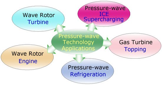
Figure 1.
Wave rotor applications.
The pressure wave supercharger is a particular type of ICE supercharger, playing the role of “compressor” for the intake of air, utilizing the energy contained within the exhaust gases, similar to a common turbocharger. The PWS exploits this energy to produce high pressure for the admission air, relying on the action of pressure waves inside the rotor’s channels. The advantages of PWS, such as a very fast response to changes in the engine load, as well as benefits in fuel consumption and exhaust emissions, recommend PWS as an appealing option for charging internal combustion engines.
3. Operating Principles
The basic operating principle consists of transferring energy throughout shock and expansion waves, which act along the circumferentially arranged channels within the cylindrical rotor, also called the “cell wheel”. The rotor moves between two stator endplates, provided with openings (ports) that let the fluids circulate: the exhaust gas at one end and air at the other, putting them into direct contact and interaction [6]. The rotor channels are periodically exposed to the air and gas inlet and outlet ports, triggering the generation of expansion and compression waves. Together with the angled arrangement of inlet and outlet ports, a boost is generated. In short terms, the expansion of exhaust gases produces shockwaves that travel within the channels toward the intake of fresh air and compress it.
The entering working fluids are the high pressure combustion gas (HPG) and the low pressure fresh air (LPA), and the outlet fluids are the low pressure gas (LPG) and the high pressure compressed air (HPA) (Figure 2). These inlet and outlet passages are connected to the admission and exhaust manifold.
Inside the channels, the unsteady processes take place at the speed of sound, the pressure wave effect being optimal for a specific operating designed point; therefore, the wave strength is diminished when the PWS works on an off-design point. This disadvantage was solved by introducing the “pockets,” thus detuning the wave behavior inside the channels by replacing a closed end with a partially opened one [10,11][10][11].
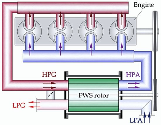
Figure 2. Pressure wave supercharger arrangement [6], Reprinted/adapted with permission from Ref. [12]. 2020, The Romanian Journal of Technical Sciences. Applied Mechanics.
Pressure wave supercharger arrangement.
The pockets, shaped within the rotor housing (EP and GP in Figure 3), allow a rapid response of the PWS to changes in engine operating requirements, as well as high efficiency and good pressure ratio curves [12,13][12][13].
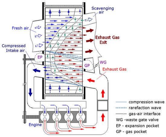
Figure 3. Fluid motion inside the PWS. Reprinted/adapted with permission from Ref. [12]. 2020, The Romanian Journal of Technical Sciences. Applied Mechanics.
Fluid motion inside the PWS.
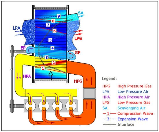
Exposing the rotor’s passages to the air outlet ports, a continuous flow of compressed air is discharged toward the admission manifold. Figure 3 and Figure 4 show unwrapped images of the processes within the channels: the fluid motion when operating at optimized speed, as well as the interfaces and the compression or expansion waves [10].
In designing and developing the PWS, many challenges had to be solved: the geometry (diameter of the rotor, length, flow-entry angles, number of channels and of cell rows), elements’ material, noise, weight and leakage effect. For instance, the number of channels influences the PWS pressure losses at the entry of fluids, increasing with the number of channels. Moreover, the rotor material has to handle all the stress caused by the high frequency shockwaves, centrifugal forces and cyclic temperature gradients. Additionally, to reduce the specific “whistle,” the solution was to break the symmetry of the channels’ section or to design multiple rows of channels [14]. Leakage was another challenge because it seriously affects PWS performance. Thus, the materials chosen for rotor and casing had to have the same expansion characteristics, and the gap between the rotor and the stator had to be minimized, hence preventing the occurrence of contact in any thermal regime [12].
PWS is usually driven by a crankshaft-driven belt or by an individual electric motor. This had to overcome the bearing friction and the windage losses, as well as assure angular momentum for the air flowing toward the rotor cells. The optimal flow-entering angles can minimize the pressure losses and reduce the necessary drive power of the PWS.