Substrate-integrated waveguide (SIW) is a modern day (21st century) transmission line that has recently been developed. This technology has introduced new possibilities to the design of efficient circuits and components operating in the radio frequency (RF) and microwave frequency spectrum. Microstrip components are very good for low frequency applications but are ineffective at extreme frequencies, and involve rigorous fabrication concessions in the implementation of RF, microwave, and millimeter-wave components. This is due to wavelengths being short at higher frequencies. Waveguide devices, on the other hand, are ideal for higher frequency systems, but are very costly, hard to fabricate, and challenging to integrate with planar components in the neighborhood. SIW connects the gap that existed between conventional air-filled rectangular waveguide and planar transmission line technologies including the microstrip.
1. Introduction
The electromagnetic (EM) spectrum is becoming overcrowded and is heavily crammed with a variety of wireless signals and other communication and sensing circuits and devices [1]. Electromagnetic waves of frequencies varying from 300 MHz up to 300 GHz stay classified as microwaves. This frequency span matches the free space wavelengths of 1 m to 1 mm, in that order. Electromagnetic waves of frequencies varying from 30 GHz to 300 GHz stay classified as millimetre-waves due to having wavelengths that lay directly over 1 mm and directly under 10 mm. The RF band falls somewhere beneath the microwave range, though the border in the middle of the radio frequency and microwave bands is subjective and changes based on the method established for developing the band [2].
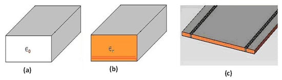
Substrate-integrated waveguide(SIW)transmission line [3][4][5][6][7][8][9][10] is basically a dielectric-filled waveguide implemented by two lines of conducting posts (also known as vias) implanted within a dielectric substrate, and electrically connecting the top and the bottom conducting walls [11]. The structural evolution of the SIW technology is shown in
1. Introduction
The electromagnetic (EM) spectrum is becoming overcrowded and is heavily crammed with a variety of wireless signals and other communication and sensing circuits and devices [1]. Electromagnetic waves of frequencies varying from 300 MHz up to 300 GHz stay classified as microwaves. This frequency span matches the free space wavelengths of 1 m to 1 mm, in that order. Electromagnetic waves of frequencies varying from 30 GHz to 300 GHz stay classified as millimetre-waves due to having wavelengths that lay directly over 1 mm and directly under 10 mm. The RF band falls somewhere beneath the microwave range, though the border in the middle of the radio frequency and microwave bands is subjective and changes based on the method established for developing the band [2].
Substrate-integrated waveguide(SIW)transmission line [3,4,5,6,7,8,9,10] is basically a dielectric-filled waveguide implemented by two lines of conducting posts (also known as vias) implanted within a dielectric substrate, and electrically connecting the top and the bottom conducting walls [11]. The structural evolution of the SIW technology is shown in Figure 1
[3]. The evolution shows how the conventional rectangular waveguide presented in Figure 1
a was modified by occupying the airspace with a dielectric material of dielectric constant, εr, as shown in
Figure 1
b. The structure was further modified by using metallic posts to imitate/replace the two side walls as shown in
Figure 1
c, to form the SIW. This paradigm shifting technology can basically be generalised as a planar transmission line that portrays waveguide characteristics, as it builds the traditional waveguide on a section of printed circuit board, substituting its metallic side-walls with two rows of metallised vias [12]. The substrate-integrated waveguide retains the benefits of a microstrip, including compactness and ease of integration, while also retaining some of the waveguide attributes, including minimal radiation loss, elevated unloaded Q-factor, and the elevated power processing capacity [13]. The very important advantage of the SIW transmission line technology is the opportunity to combine various devices (both active and passive) on a single substrate [14].
SIW structure development. (
) Air-filled rectangular waveguide. (
) Dielectric-filled rectangular waveguide. (
c) Substrate-integrated waveguide.
2. SIW Filter
The modern-day EM spectrum is becoming overcrowded and heavily inhabited with numerous wireless signals and parasitic interferers in connection with transmission and sensing services. Progressively more advanced RF, microwave, and millimetre-wave filters are essential to facilitate the passing and/or stopping of particular signals [1]. A bandpass filter selects frequency signals in a particular channel while discarding all other frequency signals external to the channel. The main function of a bandpass filter in the transmitter is to reduce the bandwidth of the output signal to the channel allocated for the transmission. Due to this, the transmitter is blocked from intruding on other stations. In the receiver, a channel filter allows signals within a specified range of frequencies to be received and interpreted, while preventing signals at unwanted frequencies from going through.
SIW filters have recently being receiving particular attention and numerous design techniques and topologies have been reported in the literature. All reported SIW filter design methods involve some sort of compromise in choosing which crucial design specifications to prioritise, including size, selectivity, power handling capability, quality factor, cost, sensitivity to environmental effects, and other performance metrics (e.g., in-band and out-band performance metrics). It is practically challenging, if not impractical, to concurrently achieve all these conflicting design requirements. Attaining higher band selectivity, for example, normally involves the use of additional resonators which implies greater insertion loss along the communication channel [15]. A collection of SIW filter design techniques were recently suggested as modifications of the conventional substrate integration waveguide filter shown in ) Substrate-integrated waveguide.
2. SIW Filter
The modern-day EM spectrum is becoming overcrowded and heavily inhabited with numerous wireless signals and parasitic interferers in connection with transmission and sensing services. Progressively more advanced RF, microwave, and millimetre-wave filters are essential to facilitate the passing and/or stopping of particular signals [1]. A bandpass filter selects frequency signals in a particular channel while discarding all other frequency signals external to the channel. The main function of a bandpass filter in the transmitter is to reduce the bandwidth of the output signal to the channel allocated for the transmission. Due to this, the transmitter is blocked from intruding on other stations. In the receiver, a channel filter allows signals within a specified range of frequencies to be received and interpreted, while preventing signals at unwanted frequencies from going through.
SIW filters have recently being receiving particular attention and numerous design techniques and topologies have been reported in the literature. All reported SIW filter design methods involve some sort of compromise in choosing which crucial design specifications to prioritise, including size, selectivity, power handling capability, quality factor, cost, sensitivity to environmental effects, and other performance metrics (e.g., in-band and out-band performance metrics). It is practically challenging, if not impractical, to concurrently achieve all these conflicting design requirements. Attaining higher band selectivity, for example, normally involves the use of additional resonators which implies greater insertion loss along the communication channel [67]. A collection of SIW filter design techniques were recently suggested as modifications of the conventional substrate integration waveguide filter shown in Figure 2 and reported in [15]. These variations including the dual-mode SIW filters [16][17], the wideband SIW filters [16], the multi-band SIW filters [18][19], and the reconfigurable SIW filters [20].
and reported in [67]. These variations including the dual-mode SIW filters [68,69], the wideband SIW filters [68], the multi-band SIW filters [70,71], and the reconfigurable SIW filters [72].
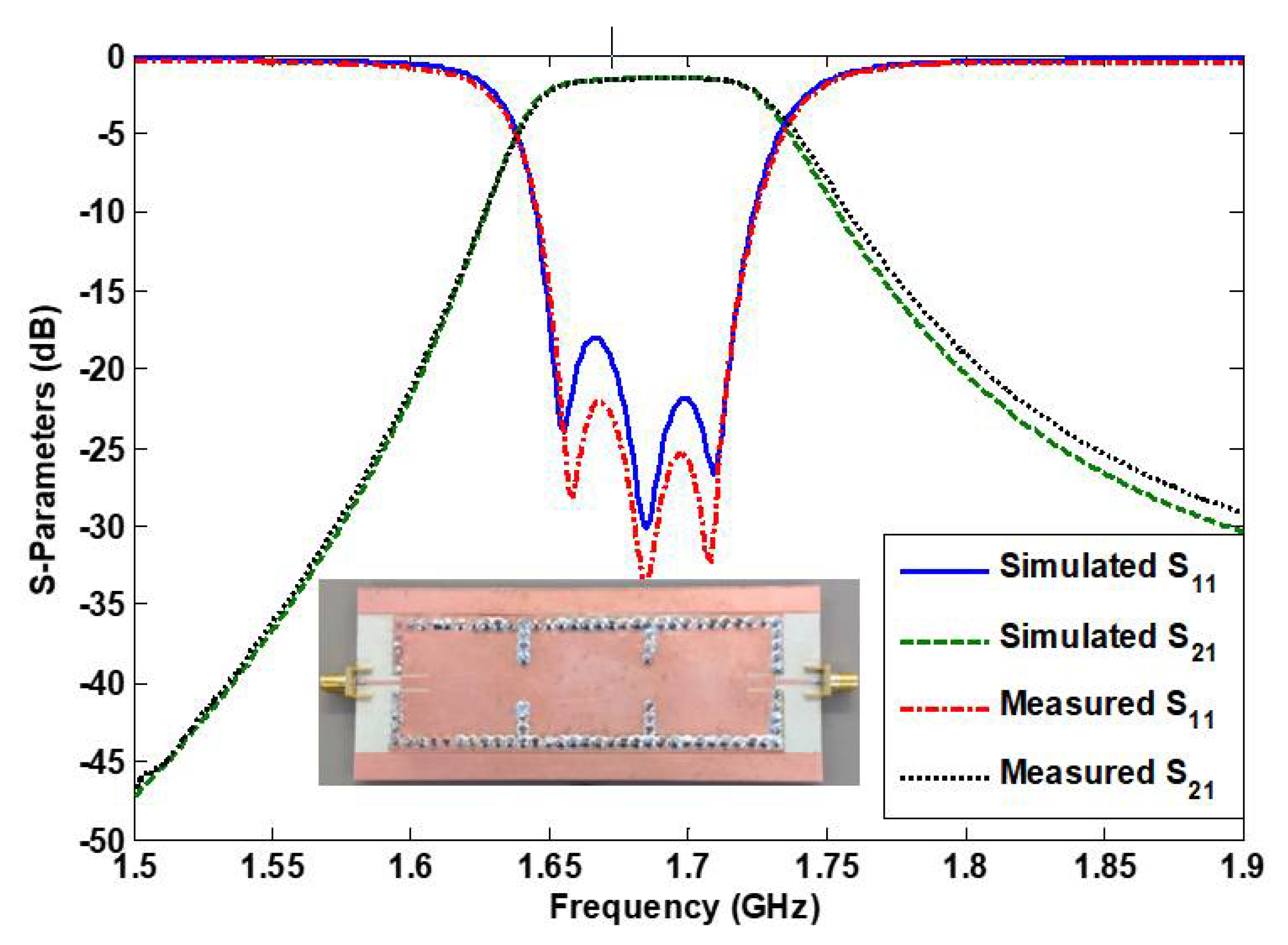
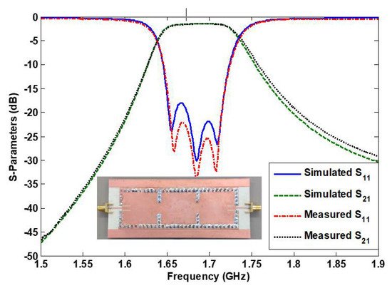
Figure 2. Simulation and measurement responses of a conventional three-pole SIW filter including the image of the fabricated filter device.
3. SIW Multiplexer
Multiplexers are microwave components employed for both breaking a frequency spectrum into two or more sub-spectrums or for merging two or more sub-spectrums into one wide spectrum. Diplexers are commonly employed in satellite communication applications to merge the transmit and the receive antennas on space vehicles [23]. This marginally lowers the size of the space vehicle by a sizeable quantity. Triplexers, on the other hand, are for linking three separate networks with distinct operational frequencies to one port [20]. Multiplexers are normally used in the RF front end of cellular radio base stations to divide the transmit and the receive channels.
Conventional SIW multiplexers (including diplexers and triplexers) are composed of several coupled single-mode SIW cavities/resonators with separate paths and a matching network as reported in [23]. Multi-mode resonators, such as the dual-mode resonator proposed in [24] and the triple-mode cavity reported in [25], have been investigated and implemented to enormously miniaturise the end device, and reduce the extent of losses recorded on the transmit/receive paths. SIW diplexers based on circular triplet combline filters have been proposed in [26]. The involvement of the cross-couplings in the circular triplet section was used to realise high rejection in the diplexer device.
4. SIW Power Divider/Combiner
Power dividers are microwave passive components that receive input signals and provide several output signals with phase and amplitude characteristics [27][28]. These components can be operated as power combiners by simply supplying signals into the divider output ports. The vector summation of the signals will appear as a single output at the divider’s input port. Integrating power dividers/combiners (PDCs) and channel filters into a single component does not only reduce the physical footprint of the component, but also helps to significantly reduce losses. The reason is that integrated filtering PDCs [29][30][31] reduce the number of lossy connectors within a communication system, since the filter and the PDC exist as a single integrated device. It has been reported in the literature [27] that Y-junction-based power dividers provide a wider bandwidth of 25.2% when compared to T-junction [32]-based power dividers which provide 10.2% bandwidth.
Various classes of SIW-based power divider/combiners have been reported in [27], including corporate (Tree), Series, multimode interference, half-mode SIW, Magic-T, radial cavity, Wilkinson and Gysel SIW power dividers. Filtering power dividers with tuneable and reconfigurable passbands has been proposed in [30], where tuneable resonators are employed to ensure the device can be used for reconfigurable applications. SIW-adjustable filtering power dividers have also been proposed in [31]. The design is based on multi-layer SIW and achieved both equal and unequal power division.
5. SIW Antennas
Antennas are the key components in wireless communication systems. Their main function is to transmit and receive signals. Further to the increasing trend concerning simplicity and miniaturisation of communication systems, it is necessary to merge antennas and filters into a solitary device that simultaneously achieves both radiating and filtering functionalities. This integrated device is known as a filtering antenna (or filtenna). The filtenna lessens the pre-filtering condition and advances the noise performance of the system.
Substrate-integrated waveguide filtering antennas are currently receiving a wide range of interest and have been achieved using different design techniques. Studies [33][34][35] proposed single band SIW filtennas with controllable radiation nulls. The radiation nulls enhance the radiation features of the filtering antennas. Electric and magnetic combined coupling structures and basic modes were used to generate two radiation nulls as explained in [33]. The two radiation nulls may be independently operated to attain elevated selectivity and flexibility in the suggested filtenna, as explained in [34]. Dual-band SIW filtering antennas have also been reported [36][37][38]. These type of filtennas have the added advantage of improved out-of-band suppression, with a multifunctional single slot. The etched multifunctional slot helps to improve the out-of-band suppression and the radiation gain. SIW filtennas have also been proposed and designed for millimetre-wave applications [39][40][41][42]. A performance-improved filtenna was exploited in [39] to act as the source of a 60 GHz Fabry–Perot Cavity antenna. This greatly improved the filtering function of the proposed filtenna. Compact size and low insertion loss was achieved in [40] by using eight-mode SIW cavities fully shielded by metallised vias. Multilayer SIW structures have also been employed in the design of antennas as reported in [41]. The structure consists of an SIW feed with a coupling slot, differential-fed L-shaped probes, and radiating patches. Researchers [42] proposed an antipodal linearly tapered slot filtenna with diverse split-ring resonators. The proposed design achieved a lower band suppression between 23.5 and 27.5 GHz. An SIW antenna based on negative order resonance is reported in [43]. The major difference between the antenna reported in [43] and those reported in [33][34][35][36][37][38][39][40][41][42] is the absence of the integrated filtering property in [43]. This simply means that, while the antennas in [33][34][35][36][37][38][39][40][41][42] will radiate energy as well as filter out unwanted frequencies, the antenna reported in [43] will only radiate energy, while depending on separately designed filters for frequency filtering.
6. SIW Sensors
Sensors and wireless identification are modern technologies with a wide range of applications. Some popular utilisations include indoor and outdoor tracking, sensing, operation of tags attached objects, human bodies, etc. Sensing and wireless identification of people and physical objects has enabled them to become smartly connected. This has led to scientific breakthroughs in various fields of human endeavours including healthcare, health monitoring, disaster monitoring, logistics, social networking, smart environments, security services, etc.
Substrate-integrated waveguides have been widely employed in achieving humidity sensors [44] and rotation sensors [45] due to their improved performance and accuracy. Microstrip-based sensors [46] normally exhibit poor quality factors and moderate sensitivity. This explains why their use is limited to testing of only medium to high-loss dielectric materials as explained in [47][48][49][50]. The SIW sensor reported in [47] was excited using an external coupling topology incorporating a transition offset. The sensor exhibits yielding at high sensitivity of 20 MHz which is equivalent to 0.67% in terms of normalised sensitivity [47]. An SIW-based sensor with negative order resonance is reported in [51]. The sensor is reported to be “compact dielectric-permittivity of liquid samples”. The sensor was implemented using SIW and achieved a compact footprint of (0.25 × 0.42)λo, where λo is the wavelength in free-space at the sensor’s operating frequency.
Simulation and measurement responses of a conventional three-pole SIW filter including the image of the fabricated filter device.
Dual-mode SIW filters are primarily developed to decrease the filter volume by at least 50% [68] when compared to the conventional SIW filter [67]. This means that a reduced filter transmission loss is guaranteed due to the halved number of resonating SIW cavities. Dual-mode SIW filters could further achieve compactness when implemented on half-mode SIW cavities as reported in [49]. A dual-mode SIW filter with flexible responses has also been suggested in [69]. The proposed technique achieved many adjustable transmission zeros. It also maintains the integrity and shielding of the SIW without increasing the design complexity [69].
Wideband substrate-integrated waveguide filters have been proposed and achieved with the transverse electromagnetic (TEM) mode transmission line because of their dispersion-free, broadband, and single-mode performance. A substrate-integrated waveguide allows only the propagation of TE modes which make the design of wideband SIW filters simpler and more achievable without the design consideration of parasitic TM modes. To increase the coupling for wideband applications, a zigzag filter topology with 28% bandwidth for European ultrawideband (UWB) applications was reported in [70]. Additional controllable cross-coupling networks are realised by both physical and nonphysical approaches to realise sharper results and more flexible alteration of the transmission zeros. A quick and correct full-wave EM analysis technique based on the boundary integral-resonant mode expansion technique was proposed and established to design the filter [68].
Mult-band SIW filters including the dual-band bandpass filter [71] and triple-band bandpass filter [72] have been reported. These design topologies are progressively becoming essential with the contemporary fast growth, development, and advancement in multi-band wireless communication systems. This type of filter is helpful in separating a small portion of a frequency band in a larger band. Reconfigurable SIW filters [73] are important for future multi-functional radio and radar systems, including smart and cognitive radio and radar systems that abound across commercial, civilian, and defence sectors. They are popular in the control and better use of the radiofrequency spectrum [68].
3. SIW Multiplexer
Multiplexers are microwave components employed for both breaking a frequency spectrum into two or more sub-spectrums or for merging two or more sub-spectrums into one wide spectrum. Diplexers are commonly employed in satellite communication applications to merge the transmit and the receive antennas on space vehicles [17]. This marginally lowers the size of the space vehicle by a sizeable quantity. Triplexers, on the other hand, are for linking three separate networks with distinct operational frequencies to one port [72]. Multiplexers are normally used in the RF front end of cellular radio base stations to divide the transmit and the receive channels.
Conventional SIW multiplexers (including diplexers and triplexers) are composed of several coupled single-mode SIW cavities/resonators with separate paths and a matching network as reported in [17]. Multi-mode resonators, such as the dual-mode resonator proposed in [74] and the triple-mode cavity reported in [75], have been investigated and implemented to enormously miniaturise the end device, and reduce the extent of losses recorded on the transmit/receive paths. SIW diplexers based on circular triplet combline filters have been proposed in [76]. The involvement of the cross-couplings in the circular triplet section was used to realise high rejection in the diplexer device.
4. SIW Power Divider/Combiner
Power dividers are microwave passive components that receive input signals and provide several output signals with phase and amplitude characteristics [78,79]. These components can be operated as power combiners by simply supplying signals into the divider output ports. The vector summation of the signals will appear as a single output at the divider’s input port. Integrating power dividers/combiners (PDCs) and channel filters into a single component does not only reduce the physical footprint of the component, but also helps to significantly reduce losses. The reason is that integrated filtering PDCs [80,81,82] reduce the number of lossy connectors within a communication system, since the filter and the PDC exist as a single integrated device. It has been reported in the literature [78] that Y-junction-based power dividers provide a wider bandwidth of 25.2% when compared to T-junction [83]-based power dividers which provide 10.2% bandwidth.
Various classes of SIW-based power divider/combiners have been reported in [78], including corporate (Tree), Series, multimode interference, half-mode SIW, Magic-T, radial cavity, Wilkinson and Gysel SIW power dividers. Filtering power dividers with tuneable and reconfigurable passbands has been proposed in [81], where tuneable resonators are employed to ensure the device can be used for reconfigurable applications. SIW-adjustable filtering power dividers have also been proposed in [82]. The design is based on multi-layer SIW and achieved both equal and unequal power division.
5. SIW Antennas
Antennas are the key components in wireless communication systems. Their main function is to transmit and receive signals. Further to the increasing trend concerning simplicity and miniaturisation of communication systems, it is necessary to merge antennas and filters into a solitary device that simultaneously achieves both radiating and filtering functionalities. This integrated device is known as a filtering antenna (or filtenna). The filtenna lessens the pre-filtering condition and advances the noise performance of the system.
Substrate-integrated waveguide filtering antennas are currently receiving a wide range of interest and have been achieved using different design techniques. Studies [84,85,86] proposed single band SIW filtennas with controllable radiation nulls. The radiation nulls enhance the radiation features of the filtering antennas. Electric and magnetic combined coupling structures and basic modes were used to generate two radiation nulls as explained in [84]. The two radiation nulls may be independently operated to attain elevated selectivity and flexibility in the suggested filtenna, as explained in [85]. Dual-band SIW filtering antennas have also been reported [87,88,89]. These type of filtennas have the added advantage of improved out-of-band suppression, with a multifunctional single slot. The etched multifunctional slot helps to improve the out-of-band suppression and the radiation gain. SIW filtennas have also been proposed and designed for millimetre-wave applications [90,91,92,93]. A performance-improved filtenna was exploited in [90] to act as the source of a 60 GHz Fabry–Perot Cavity antenna. This greatly improved the filtering function of the proposed filtenna. Compact size and low insertion loss was achieved in [91] by using eight-mode SIW cavities fully shielded by metallised vias. Multilayer SIW structures have also been employed in the design of antennas as reported in [92]. The structure consists of an SIW feed with a coupling slot, differential-fed L-shaped probes, and radiating patches. The authors of [93] proposed an antipodal linearly tapered slot filtenna with diverse split-ring resonators. The proposed design achieved a lower band suppression between 23.5 and 27.5 GHz. An SIW antenna based on negative order resonance is reported in [94]. The major difference between the antenna reported in [94] and those reported in [84,85,86,87,88,89,90,91,92,93] is the absence of the integrated filtering property in [94]. This simply means that, while the antennas in [84,85,86,87,88,89,90,91,92,93] will radiate energy as well as filter out unwanted frequencies, the antenna reported in [94] will only radiate energy, while depending on separately designed filters for frequency filtering.
6. SIW Sensors
Sensors and wireless identification are modern technologies with a wide range of applications. Some popular utilisations include indoor and outdoor tracking, sensing, operation of tags attached objects, human bodies, etc. Sensing and wireless identification of people and physical objects has enabled them to become smartly connected. This has led to scientific breakthroughs in various fields of human endeavours including healthcare, health monitoring, disaster monitoring, logistics, social networking, smart environments, security services, etc.
Substrate-integrated waveguides have been widely employed in achieving humidity sensors [95] and rotation sensors [96] due to their improved performance and accuracy. Microstrip-based sensors [97] normally exhibit poor quality factors and moderate sensitivity. This explains why their use is limited to testing of only medium to high-loss dielectric materials as explained in [98,99,100,101]. The SIW sensor reported in [98] was excited using an external coupling topology incorporating a transition offset. The sensor exhibits yielding at high sensitivity of 20 MHz which is equivalent to 0.67% in terms of normalised sensitivity [98]. An SIW-based sensor with negative order resonance is reported in [102]. The sensor is reported to be “compact dielectric-permittivity of liquid samples”. The sensor was implemented using SIW and achieved a compact footprint of (0.25 × 0.42)λo, where λo is the wavelength in free-space at the sensor’s operating frequency.