Proximal humerus fractures are becoming more common due to the aging of the population, and more related scientific research is also emerging. Biomechanical studies attempt to optimize treatments, taking into consideration the factors involved, to obtain the best possible treatment scenario. To achieve this, the use of finite element analysis (FEA) is necessary, to experiment with situations that are difficult to replicate, and which are sometimes unethical. Furthermore, low costs and time requirements make FEA the perfect choice for biomechanical studies. Part of the complete process of an FEA involves three-dimensional (3D) bone modeling, mechanical properties assignment, and meshing the bone model to be analyzed. Due to the lack of standardization for bone modeling, properties assignment, and the meshing processes, this article aims to review the most widely used techniques to model the proximal humerus bone, according to its anatomy, for FEA.
- proximal humerus
- finite element analysis
- bone model
- humerus anatomy
- proximal humerus mechanical properties
- meshing properties
1. Introduction
- Introduction
Fracture of the proximal humerus is becoming one of the most common injuries among the elderly and is related to osteoporosis, which deteriorates the microstructure of the bone and decreases its bone mass [1][2][3][4][5][1–5]. Fracture risk will increase with population aging [6][7][8][6–8]: the changes that come with the biological aging process make the elderly more susceptible to suffering a fracture, given that falls are the major risk factor for this group, along with osteoporosis [9][10][11][12][9–12].
The treatment for this type of fracture is still debatable, due to the fracture/patient factors involved in the treatment decision process, and the high complication rates of surgical treatments. The stability and displacement of the fracture, the bone mineral density, the fracture pattern, and the age and comorbidities of the patient are some of the factors to consider for the proper selection of treatment [13][14][15][3,4,13–15]. The potential poor outcomes of surgical treatments include non-union, varus collapse, screw-cut, loss of reduction, avascular necrosis, and the need for reoperation [16][17][14,16,17].
Therefore, computational biomechanical studies have become more common, which try to solve and validate the different aspects of fracture treatments and enhance their outcomes through finite element analysis (FEA), providing a fast and low-cost experimentation technique and, most importantly, helping to prevent premature failures through fracture/treatment behavior analysis via three-dimensional (3D) models. An FEA can provide information on realistic bone behavior in specific scenarios through a three-dimensional simulation, as long as the mesh parameters, constraints, and mechanical properties are properly selected, especially for the bone [18][19][18,19].
Nevertheless, discrepancies exist between studies due to the lack of standards for the characterization of the bone model, including in proximal humerus studies. Each researcher uses different bone material properties and natures; for instance, there are studies were the orthotropic nature is preferred for the bone [20][21][20,21], while others use the isotropic nature [22][23][24][25][26][27][28][3,5,22–28], even when anisotropy is the actual nature of bone tissues. The research papers also differ in their modeling technique. Some researchers consider the bone as a solid and “homogeneous” model, without distinguishing between the different bone tissue [25][26][25,26], while other studies use a threshold to separate cancellous and cortical bone in order to maintain real bone structure in their model [29][30][31][3,5,20,29–31]. What is more, each researcher uses dissimilar meshing parameters for their FEA bone models—crucial parameters for the accuracy of outcomes, which vary from the type of element to the element’s edge length.
Hence, this article aims to review the most used bone characterization techniques for the proximal humerus in FEA biomechanical studies, analyzing the different aspects of the modeling process, from bone geometry simplification to the most used mesh parameters. The strengths and limitations of these FEA characterization techniques will also be reviewed, starting from the most basic knowledge you must possess about the proximal humerus to be able to apply them, and considering how to achieve the best and closest-to-reality results from an FEA through the use of revised techniques.
2. Proximal Humerus Anatomy and Bone Composition
- Proximal Humerus Anatomy and Bone Composition
2.1. Bone Shape
Knowledge of the bone anatomy you are working with is a critical part of the modeling process, as the virtual representation must be as close to reality as possible to achieve accurate results. For instance, knowing the composition of the proximal humerus allows one to understand and represent the different types of fracture patterns in an FEA, as well as knowing where the bone should be fixed and where loads should be applied to obtain a good representation of a real-life situation or a particular experimental setting [32][33][18,32,33].
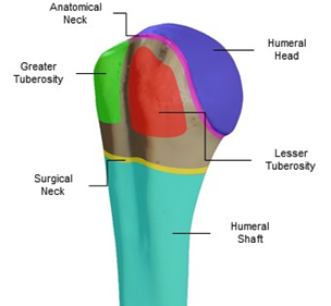
The geometry of the proximal humerus can be classified into four main sections: the humeral head (articular surface), greater and lesser tuberosities, and the humeral shaft (Figure 1). The humeral head articulates with the glenoid cavity to form the glenohumeral joint, which is the main joint of the shoulder’s joint system (glenohumeral, acromioclavicular, scapulothoracic, and sternoclavicular joints) and allows shoulder movement. The humeral head has a curvature diameter between 37.1 and 58 mm [34][35][34,35]. The tuberosities function to attach the rotator cuff tendons, and the distance from the highest point of the humeral head to the top of the greater tuberosity is usually an average of 8 +/- 3.2 mm [36][37][38][36–38].
Figure 1. Proximal humerus anatomy, sectioned by colors: the humeral head (blue), greater (green) and lesser (red) tuberosities, anatomical neck (magenta), surgical neck (yellow), and humeral shaft (cyan).
These sections were used to create the proximal humerus classification systems that we still use today, such as the Neer Classification from 1979 [39], Hertel’s binary description for proximal humerus fractures [40], and the AO Foundation/Orthopedic Trauma Association (AO/OTA) classification, the latter of which is one of the most recent and detailed classifications [41]. Other important sections of the proximal humerus are the anatomical and surgical neck: the anatomical neck is the bony portion where the humeral head and the humeral shaft meet, and the surgical neck is the section just below both tuberosities. The bicipital groove separates the greater tuberosity from the lesser one, and is where the long head of the biceps runs to the shoulder joint [4,36,37].
2.2. Muscles, Tendons, and Movements
As well as the main parts of the proximal humerus anatomy, the forces that the muscles and tendons generate on the bone are equally important when running an FEA, since they are responsible for the movement of the bone in the simulation and the reaction forces caused by the combination of these loads, which allow us to perform multiple analyses using an FEA. Thus, knowing which muscle and tendons have an effect on the bone, and to what magnitude depending on the specific movement, grants us the ability to replicate the behavior of a real patient in a simulation.
The proximal humerus is constantly subjected to torsion, compression, flexion, tension, and the combination of these, caused by combined forces and torques induced by the muscles and tendons attached to it (Figure 2), allowing shoulder movement and establishing the movement range. The humeral shaft is attached to the deltoid and pectoralis major. Attached to the greater tuberosity are the supraspinatus, infraspinatus, and teres minor, and positioned superior, posterosuperior, and posterior, respectively. For the lesser tuberosity, only the subscapularis is attached [42][13,16,36,37,42]. The balance between the deltoid and rotator cuff (supraspinatus, infraspinatus, subscapularis, supraspinatus, and teres minor) provides the correct variable forces to move the arm naturally.
Figure 2. Position of the different muscles attached to the proximal humerus that allow the movement of the arm. The described muscles are the supraspinatus (blue), infraspinatus (green), teres minor (red), subscapularis (yellow), and pectoralis major (magenta).
If we isolate the natural movements of the shoulder, we obtain three main movements and their counter-movements. First, we have the flexion and extension movements, which consist of raising the limb forward and backward from the sagittal plane, respectively. The supraspinatus and infraspinatus have significant roles in flexion, unlike in extension where the subscapularis does the work [43]. Then, there is abduction and adduction, which are the movement of the limb away and towards the midplane of the coronal plane, respectively. For abduction, the use of the muscle and tendon will vary depending on the elevation angle. The supraspinatus has a greater impact at the beginning of the elevation, then the deltoid becomes more significant. In adduction, the pectoralis major does the work [44]. Finally, internal/external rotation consists of arm rotation towards/away from the centerline of the coronal plane. The muscles and tendons used in external rotation are the infraspinatus and teres minor. In the counterpart movement, the internal rotation uses the subscapularis and pectoralis major most [45]. This series of movements is generally used to study the progress of rehabilitation, but also for biomechanical analysis and experimentation.
2.3. Bone Composition: Proximal Humerus
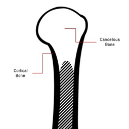
As a long bone, the proximal humerus is composed macroscopically of cancellous bone and cortical bone (Figure 3). The proportions between them will always vary, depending on age, comorbidities, bone diseases, and so forth. The cortical bone forms the external cortex of the bone, and can be found in the shafts (diaphysis) of long bones. Its porosity is low, being a more compact and dense bone tissue, varying from 5% to 30%. Almost 80% of the body’s total bone mass is cortical bone. On the contrary, cancellous bone is less dense, with porosity of up to 90%, being softer and more flexible than cortical tissue [18].
The shaft of the proximal humerus is mainly cortical bone, and shows the highest bone mineral density (BMD) values of the proximal humerus due to its compactness and thickness. However, its thickness gradually decreases towards the humeral head [4]. The humeral head is made primarily of cancellous bone, covered by a thin layer of cortical bone as a cortex [3,4,16].
Figure 3. Bone composition of the proximal humerus: the thickest cortical bone (contour) can be found on the shaft and begins to get thinner towards the humeral head, whereas the humeral head is mainly made of cancellous bone covered with a thin cortical bone layer.


