Voltage-source converter (VSC) HVDC systems based on modular multilevel converters (MMCs) combine the system advantages of fast and independent active and reactive power control, passive network supply, black start capabilities, frequency support and power oscillation damping with power electronics benefits such as scalable design, increased reliability, lower conversion losses and reduced filtering requirements, thus offering a commercially competitive solution. The structure of the SM is an important element of the MMC and multiple SM circuit topologies and configurations have been proposed in the existing literature. This has been the case, especially in recent years, where substantial SM topologies have been presented, specifically aimed at extending the functionalities of the MMC, in many cases aligned with niche applications of the converter rather than generic use as a VSC converter.
- high-voltage direct current (HVDC)
- modular multilevel converter
- multilevel converters
- submodules/cells
1. Submodule (SM) Configurations
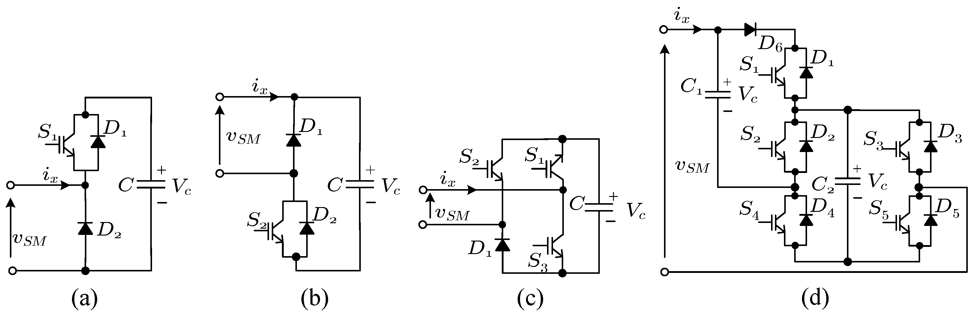
1.1. Half and Full-Bridge Sub-Modules
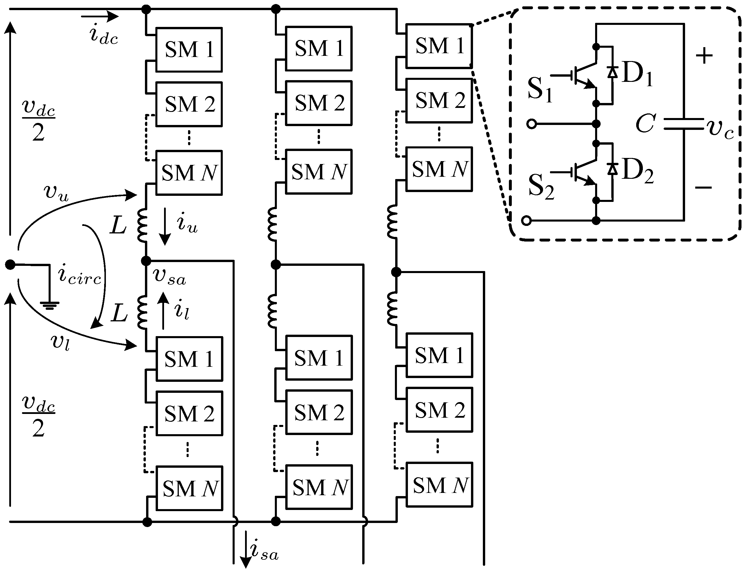
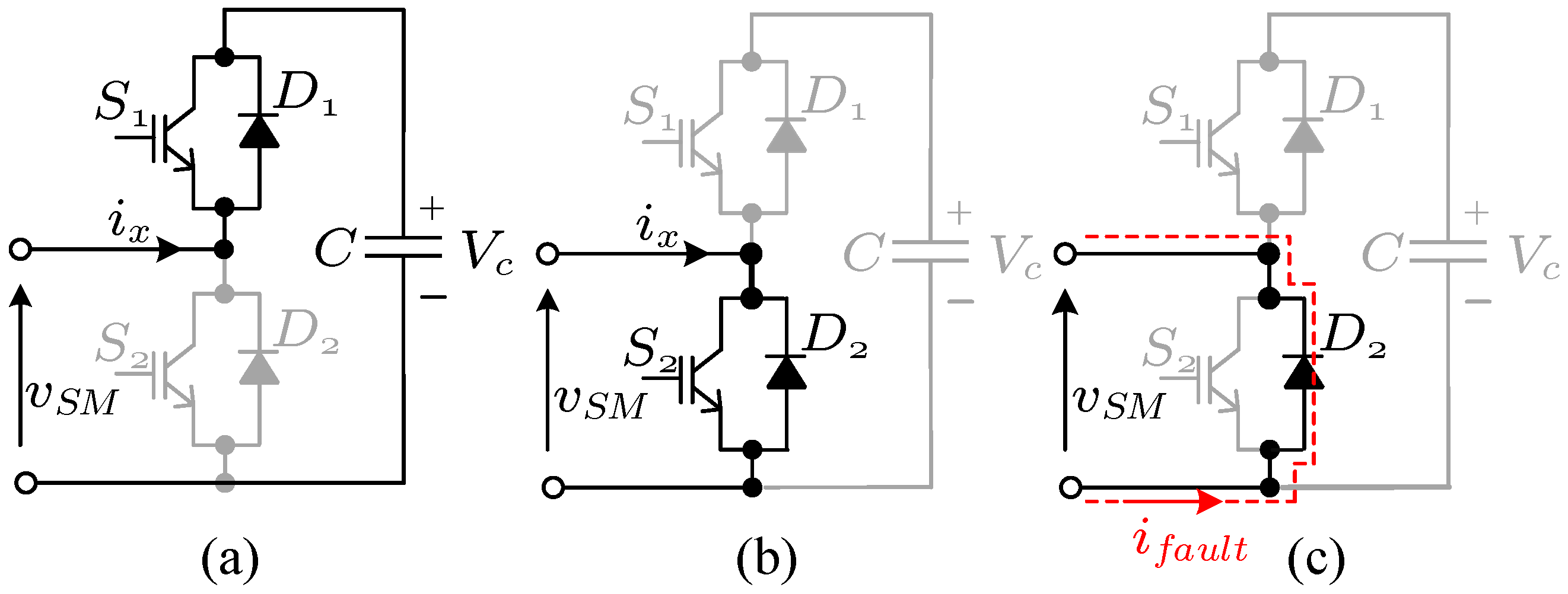
1.1.1. The Half-Bridge Submodule (HB-SM)
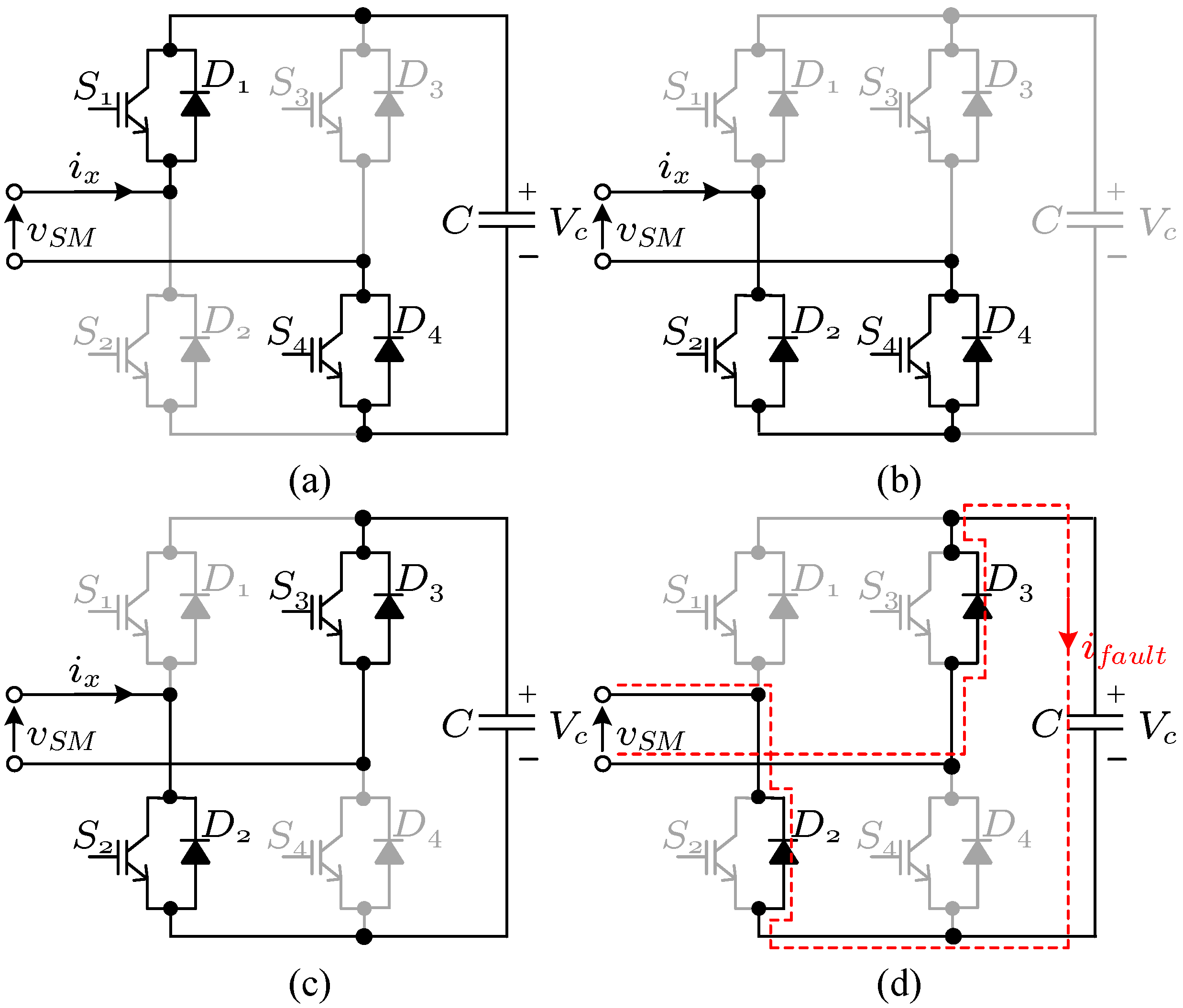
1.1.2. The Full-Bridge Submodule (FB-SM)
1.2. Unipolar SMs
1.3. Bipolar SMs
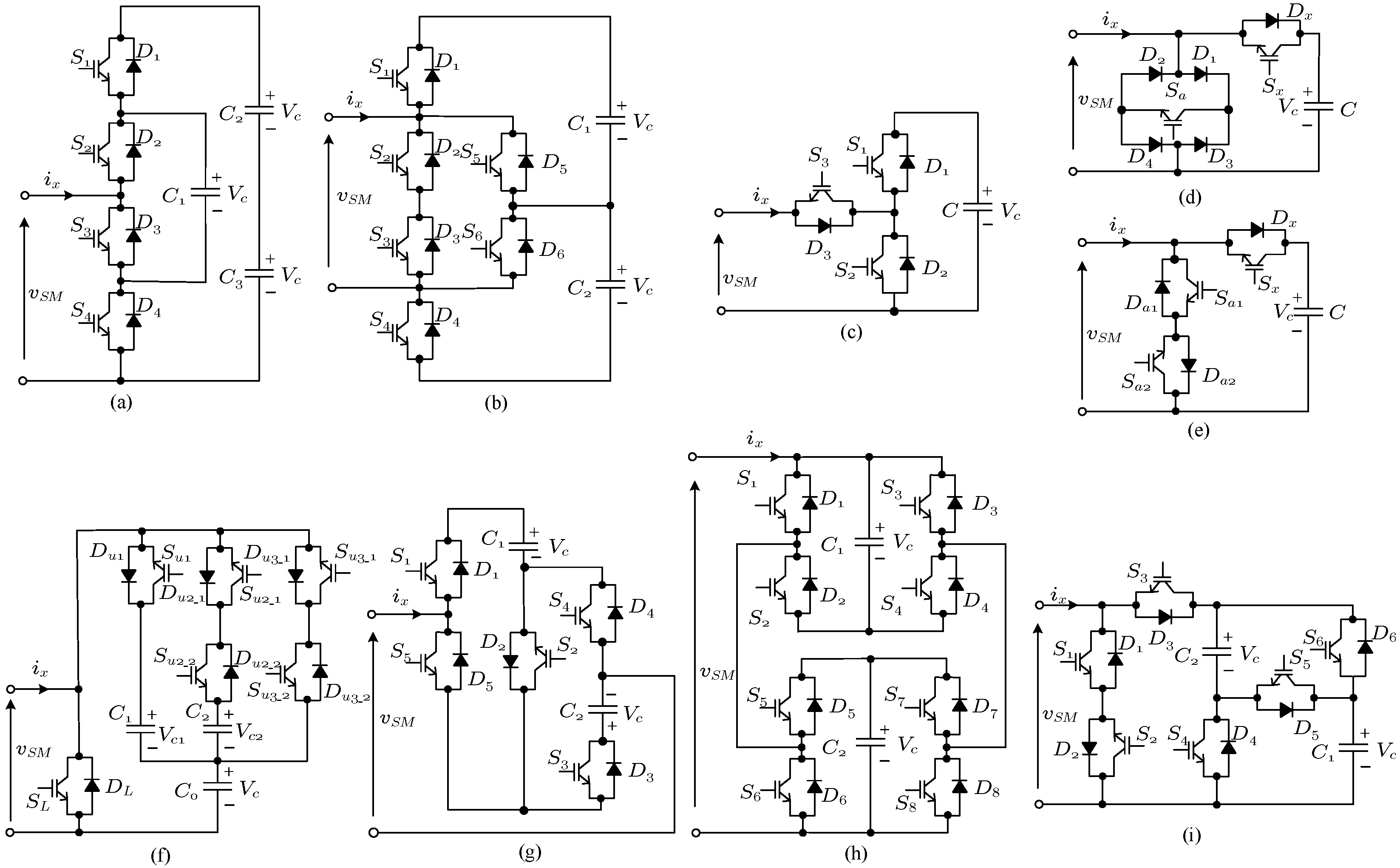
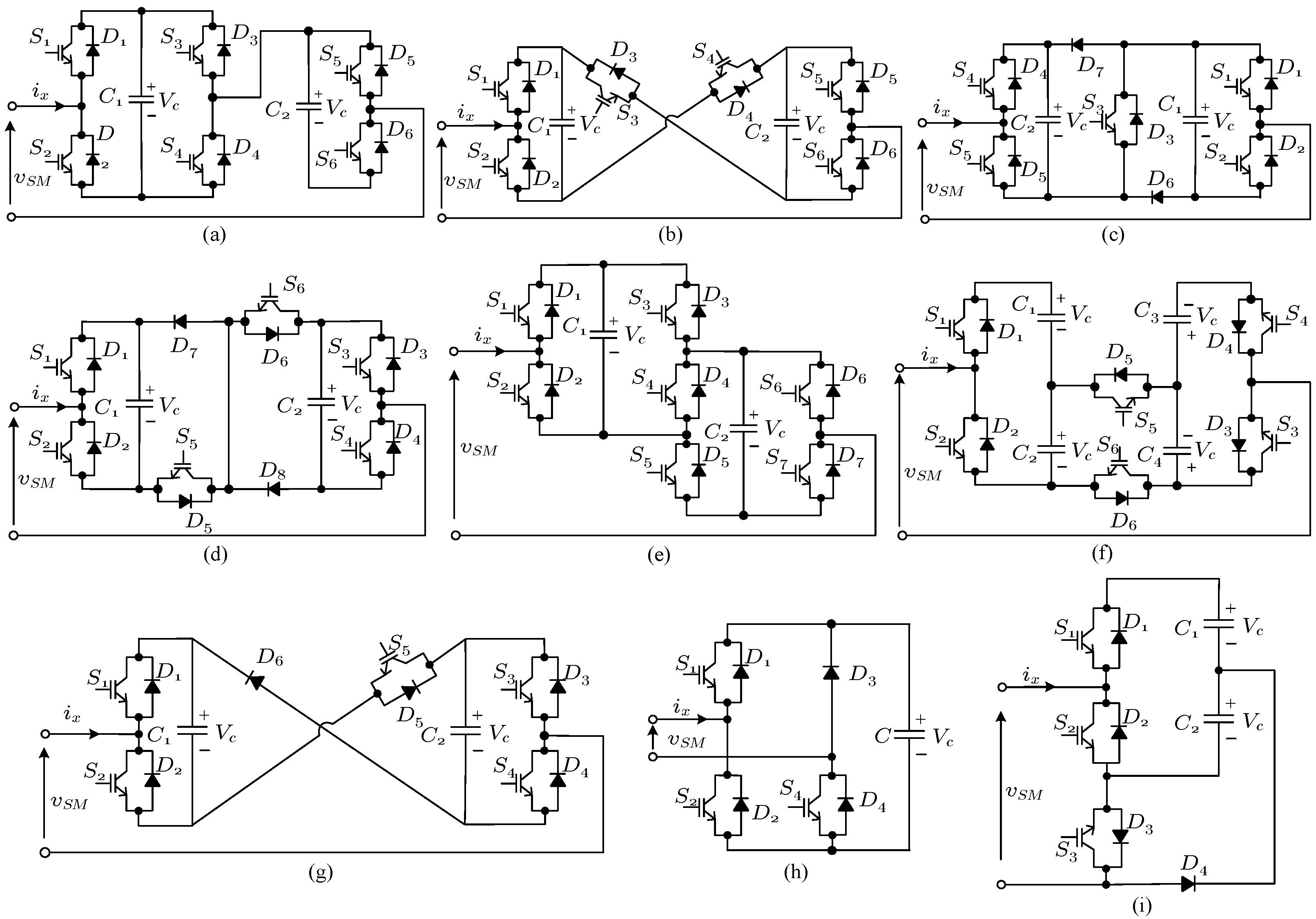

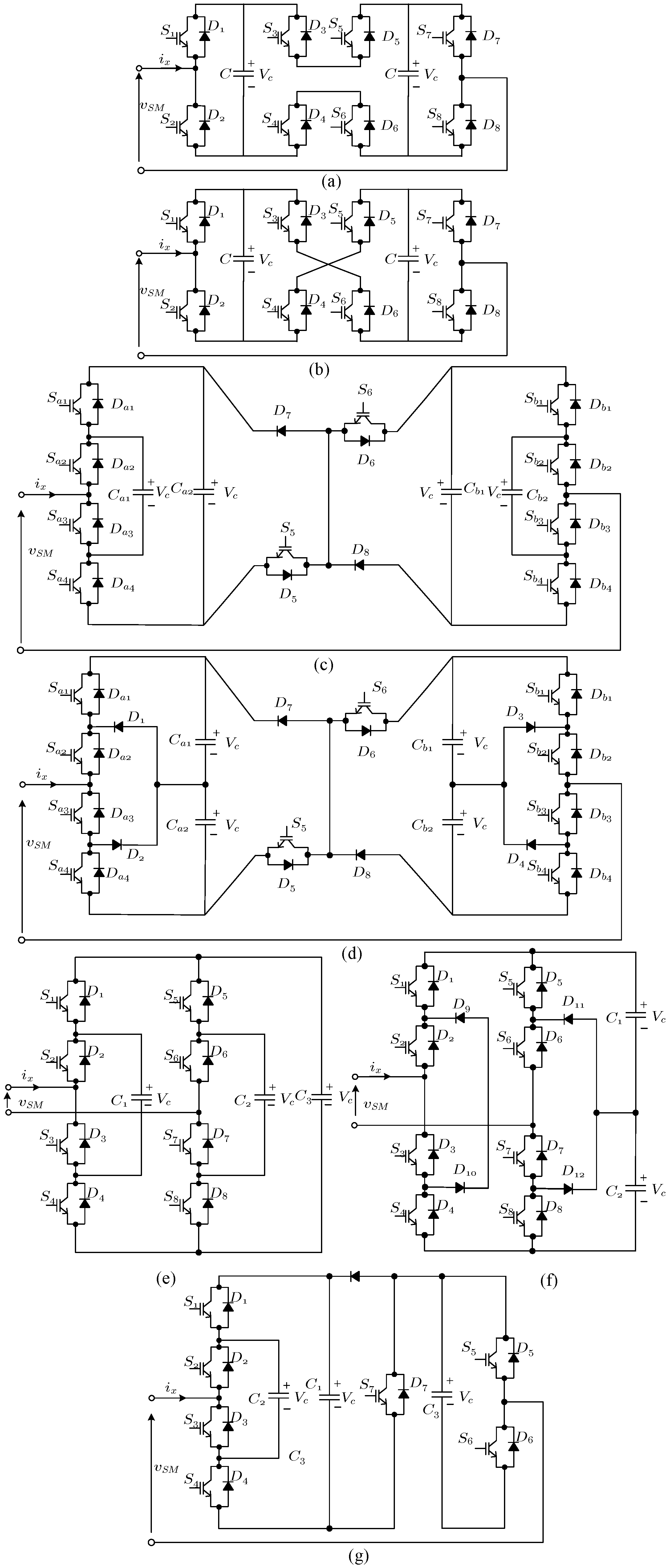
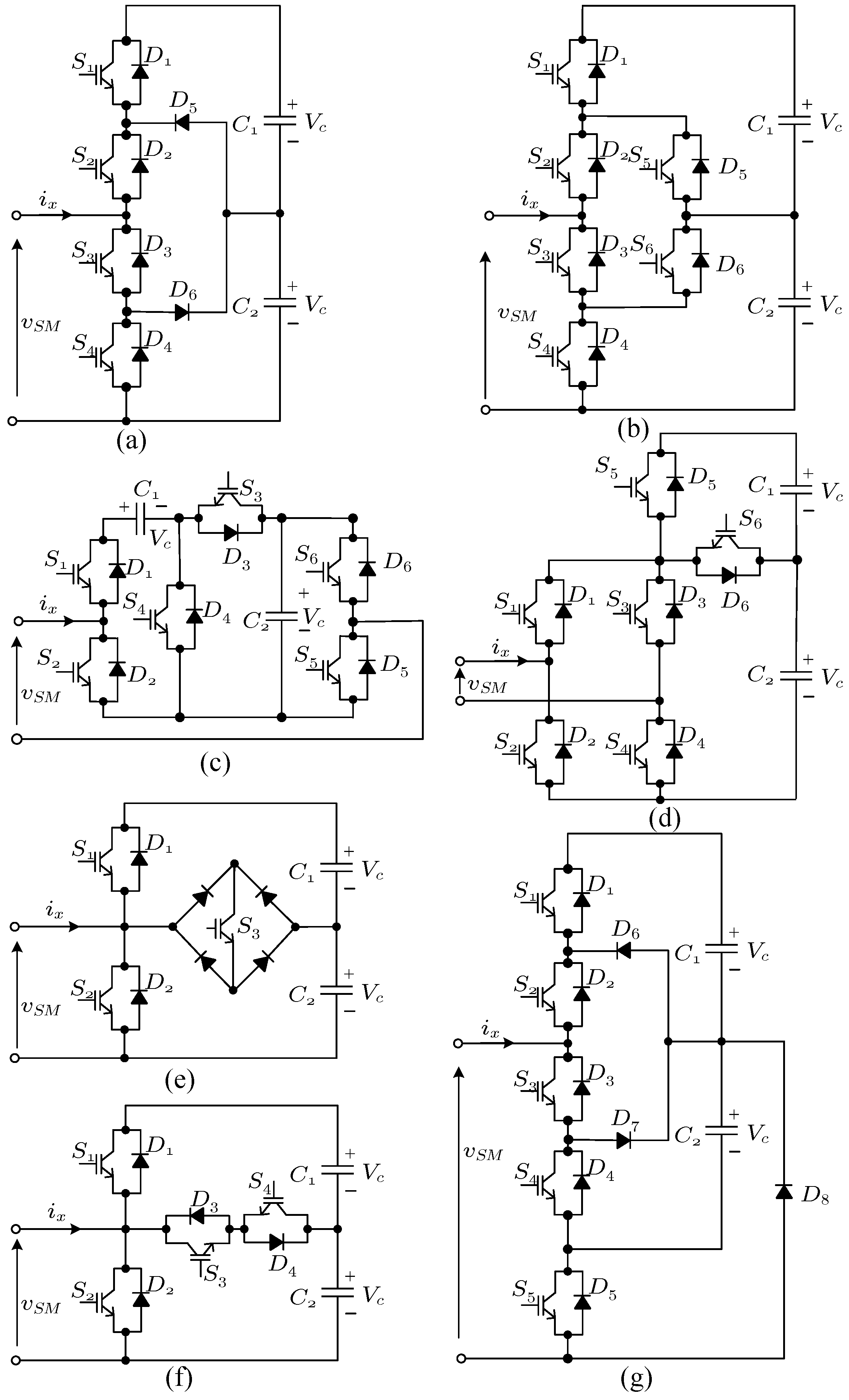
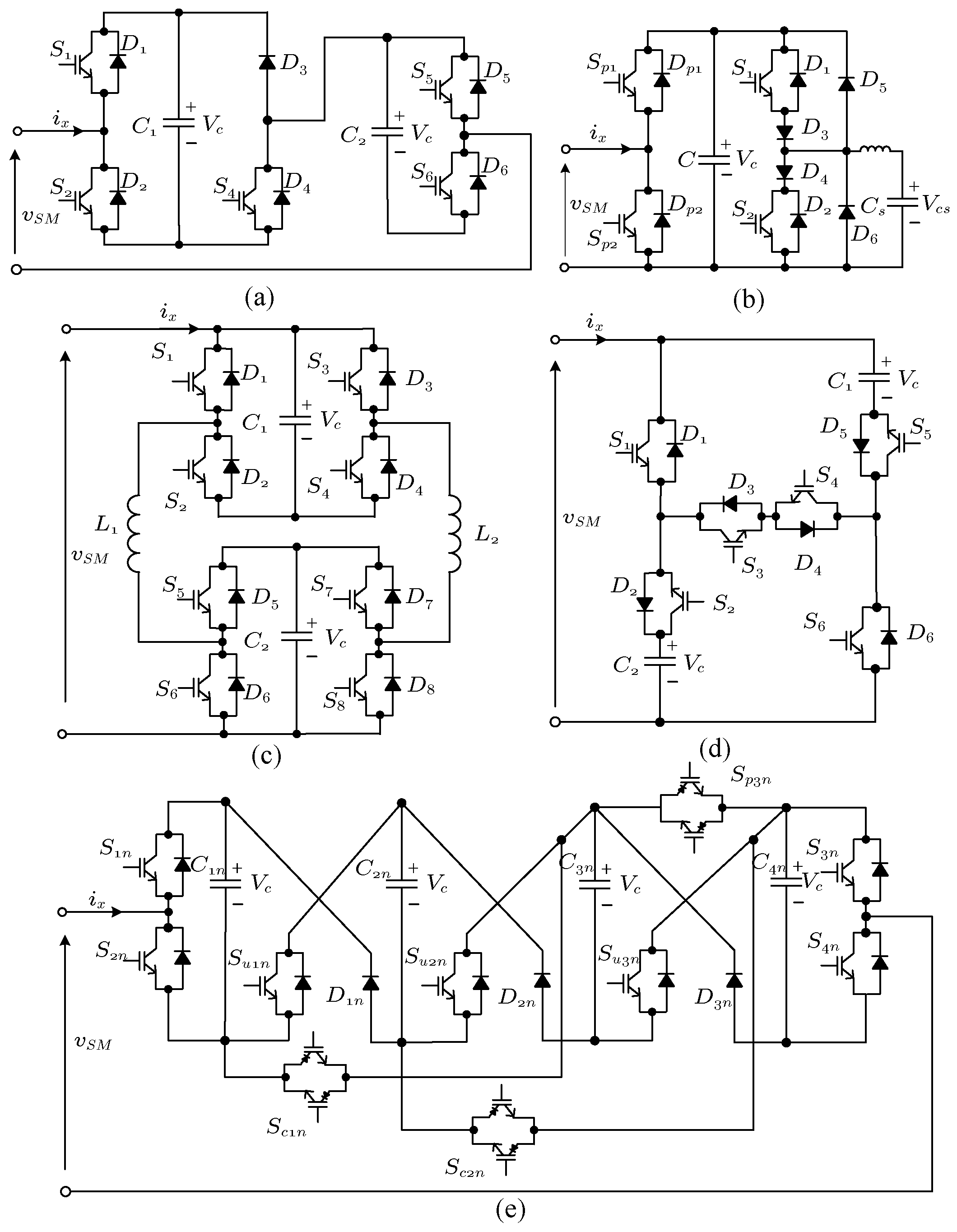
1.4. Multilevel SMs
1.5. SMs with Voltage Balancing Limitations
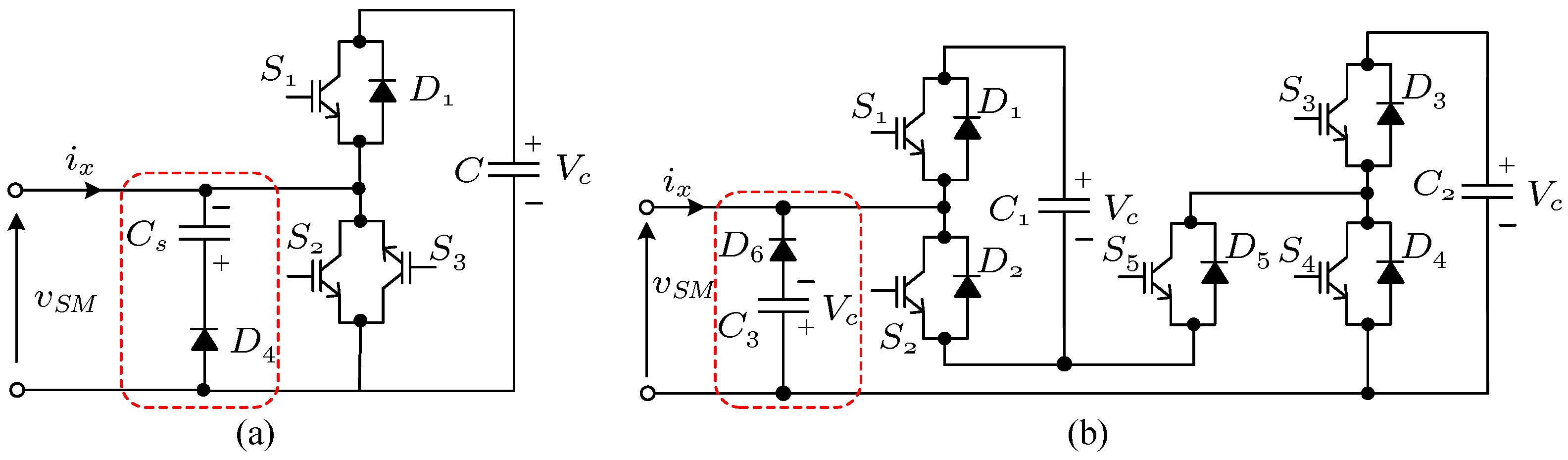
1.6. Unidirectional SMs
1.7. Other VSC SMs
1.8. Csc and AC-AC Submodules
2. SM Classifications
The Figure 12 is about the timeline of SM introduction in the literature and the Figure 13 is about the classification of SMs based on number of positive and negative levels in their output voltage.
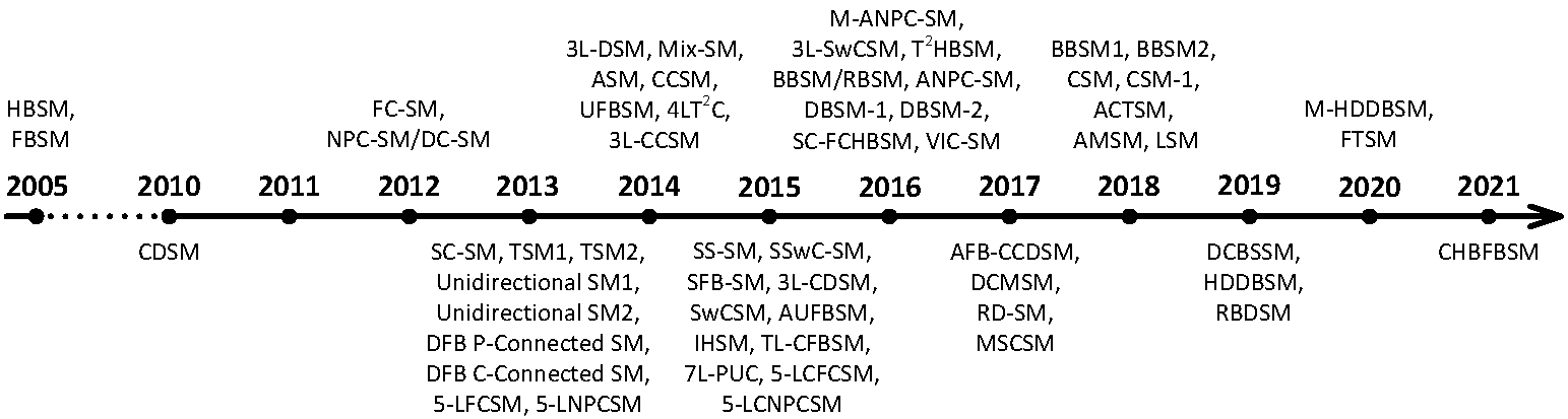
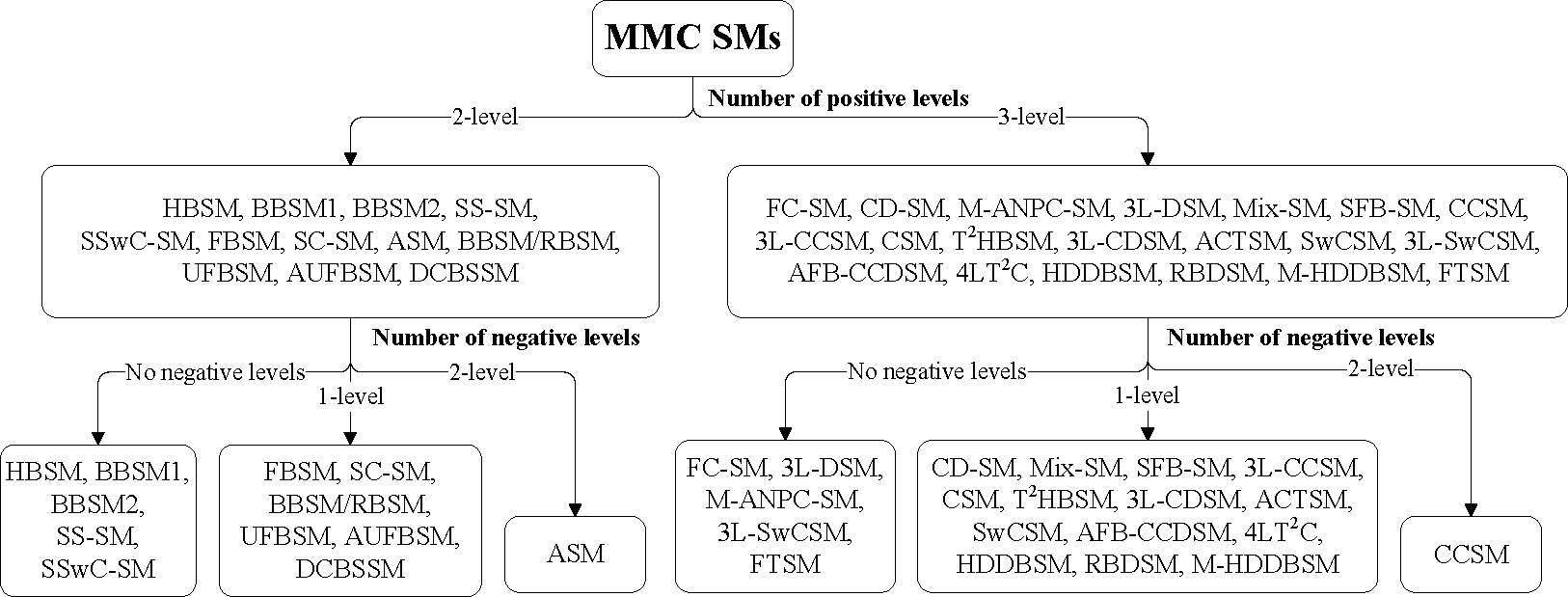
Figure 13. Classification of SMs based on number of positive and negative levels in their output voltage.
References
- Bösche, D.; Wilkening, E.D.; Köpf, H.; Kurrat, M. Hybrid DC Circuit Breaker Feasibility Study. IEEE Trans. Components Packag. Manuf. Technol. 2017, 7, 354–362.
- Lin, W.; Jovcic, D.; Nguefeu, S.; Saad, H. Full-Bridge MMC Converter Optimal Design to HVDC Operational Requirements. IEEE Trans. Power Deliv. 2016, 31, 1342–1350.
- Zhao, C.; Li, Y.; Konstantinou, G.; Li, Z.; Wang, P.; Lei, M.; Xu, F.; Liu, Z. Energy storage requirements of full-bridge modular multilevel converter with zero sequence voltage injection. In Proceedings of the IECON 2017—43rd Annual Conference of the IEEE Industrial Electronics Society, Beijing, China, 29 October–1 November 2017; pp. 4512–4517.
- Townsend, C.; Goodwin, G.C.; Konstantinou, G.; Petranovic, N.; Mirzaeva, G.; Farivar, G.; Pou, J. Identifying Circulating Currents and Zero-Sequence Voltages for Reduction in Stored Capacitor Energy in Modular Multilevel Converters. IEEE Trans. Ind. Electron. 2020, 68, 454–465.
- Wickramasinghe, H.R.; Konstantinou, G.; Pou, J. Comparison of bipolar sub-modules for the alternate arm converter. Electr. Power Syst. Res. 2017, 146, 115–123.
- Zeng, R.; Xu, L.; Yao, L.; Williams, B.W. Design and Operation of a Hybrid Modular Multilevel Converter. IEEE Trans. Power Electron. 2015, 30, 1137–1146.
- Elserougi, A.A.; Abdel-Khalik, A.S.; Massoud, A.M.; Ahmed, S. A New Protection Scheme for HVDC Converters Against DC-Side Faults with Current Suppression Capability. IEEE Trans. Power Deliv. 2014, 29, 1569–1577.
- Solas, E.; Abad, G.; Barrena, J.A.; Aurtenetxea, S.; Cárcar, A.; Zając, L. Modular Multilevel Converter with Different Submodule Concepts—Part I: Capacitor Voltage Balancing Method. IEEE Trans. Ind. Electron. 2013, 60, 4525–4535.
- Adam, G.P.; Abdelsalam, I.; Fletcher, J.E.; Burt, G.M.; Holliday, D.; Finney, S.J. New Efficient Submodule for a Modular Multilevel Converter in Multiterminal HVDC Networks. IEEE Trans. Power Electron. 2017, 32, 4258–4278.
- Nguyen, T.H.; Lee, D. A novel submodule topology of MMC for blocking DC-fault currents in HVDC transmission systems. In Proceedings of the 2015 9th International Conference on Power Electronics and ECCE Asia (ICPE-ECCE Asia), Seoul, Korea, 1–5 June 2015; pp. 2057–2063.
- Ahmed, K.H.; Adam, G.P.; Abdelsalam, I.A.; Aboushady, A.A. Modular multilevel converter with modified half-bridge submodule and arm filter for dc transmission systems with dc fault blocking capability. IET Power Electron. 2018, 11, 2253–2262.
- Tang, Y.; Chen, M.; Ran, L. A Compact MMC Submodule Structure With Reduced Capacitor Size Using the Stacked Switched Capacitor Architecture. IEEE Trans. Power Electron. 2016, 31, 6920–6936.
- Tang, Y.; Chen, M.; Ran, L. Design and control of a compact MMC submodule structure with reduced capacitor size using the stacked switched capacitor architecture. In Proceedings of the 2016 IEEE Applied Power Electronics Conference and Exposition (APEC), Long Beach, CA, USA, 20–24 March 2016; pp. 1443–1449.
- Elserougi, A.; Ahmed, S.; Massoud, A. A new three-level switched-capacitor submodule for modular multilevel converters. In Proceedings of the 2016 IEEE International Conference on Industrial Technology (ICIT), Taipei, Taiwan, 14–17 March 2016; pp. 234–239.
- Ilves, K.; Taffner, F.; Norrga, S.; Antonopoulos, A.; Harnefors, L.; Nee, H. A Submodule Implementation for Parallel Connection of Capacitors in Modular Multilevel Converters. IEEE Trans. Power Electron. 2015, 30, 3518–3527.
- Nami, A.; Liang, J.; Dijkhuizen, F.; Demetriades, G.D. Modular Multilevel Converters for HVDC Applications: Review on Converter Cells and Functionalities. IEEE Trans. Power Electron. 2015, 30, 18–36.
- Marquardt, R. Modular Multilevel Converter: An universal concept for HVDC-Networks and extended DC-Bus-applications. In Proceedings of the The 2010 International Power Electronics Conference—ECCE ASIA, Sapporo, Japan, 21–24 June 2010; pp. 502–507.
- Zhang, J.; Jiang, C.; Han, Y. Modular multilevel converter composite submodule topology and control. J. Eng. 2019, 2019, 2643–2648.
- Nami, A.; Adabi, J. A new T-type NPC-based submodule for modular multilevel cascaded converters. In Proceedings of the The 5th Annual International Power Electronics, Drive Systems and Technologies Conference (PEDSTC 2014), Tehran, Iran, 5–6 February 2014; pp. 137–142.
- Zhao, F.; Xiao, G.; Yang, D.; Liu, M.; Han, X.; Liu, B. A novel T-type half-bridge cell for modular multilevel converter with DC fault blocking capability. In Proceedings of the 2016 IEEE Energy Conversion Congress and Exposition (ECCE), Milwaukee, WI, USA, 18–22 September 2016; pp. 1–6.
- Hu, X.; Zhang, J.; Xu, S.; Jiang, Y. Investigation of a new modular multilevel converter with DC fault blocking capability. In Proceedings of the 2017 IEEE Energy Conversion Congress and Exposition (ECCE), Cincinnati, OH, USA, 1–5 October 2017; pp. 4902–4907.
- Elserougi, A.A.; Massoud, A.M.; Ahmed, S. A Switched-Capacitor Submodule for Modular Multilevel HVDC Converters with DC-Fault Blocking Capability and a Reduced Number of Sensors. IEEE Trans. Power Deliv. 2016, 31, 313–322.
- Kim, H.; Kang, J.; Kim, S.; Kim, C.; Hur, K. DC fault protection for modular multilevel converter HVDC using asymmetrical unipolar full-bridge submodule. In Proceedings of the 2015 9th International Conference on Power Electronics and ECCE Asia (ICPE-ECCE Asia), Seoul, Korea, 1–5 June 2015; pp. 1083–1089.
- Wang, R.; Li, Z.; Wen, X.; Liu, N.; Wang, X. A Novel MMC Sub-Module Topology With DC Fault Clearance Capability. IEEE Access 2019, 7, 96085–96093.
- Zhang, J.; Cui, D.; Tian, X.; Zhao, C. Hybrid double direction blocking sub-module for MMC-HVDC design and control. J. Power Electron. 2019, 19, 1486–1495.
- Peng, C.; Li, R. A Low Conduction Loss Modular Multilevel Converter Topology With DC Fault Blocking Capability and Reduced Capacitance. IEEE Trans. Circuits Syst. II Express Briefs 2020, 67, 1299–1303.
- Peng, C.; Li, R. A Low Conduction Loss Modular Multilevel Converter Sub-Module Topology with DC Fault blocking Capability. In Proceedings of the 2020 IEEE Applied Power Electronics Conference and Exposition (APEC), New Orleans, LA, USA, 15–19 March 2020; pp. 535–539.
- Yang, X.; Xue, Y.; Chen, B.; Lin, Z.; Mu, Y.; Zheng, T.Q.; Igarshi, S. Reverse blocking sub-module based modular multilevel converter with DC fault ride-through capability. In Proceedings of the 2016 IEEE Energy Conversion Congress and Exposition (ECCE), Milwaukee, WI, USA, 18–22 September 2016; pp. 1–7.
- Zhang, Z.; Jia, L.; Yang, L.; Zhang, Z.; Zhai, Z.; Wang, Y. An Improved Topology of Sub-module for MMC with DC Fault Clearing Ability. In Proceedings of the 2019 IEEE 4th International Future Energy Electronics Conference (IFEEC), Singapore, 25–28 November 2019; pp. 1–6.
- Kangarlu, M.F.; Babaei, E. Cross-switched multilevel inverter: An innovative topology. IET Power Electron. 2013, 6, 642–651.
- Chaudhuri, T. Cross Connected Multilevel Voltage Source Inverter Topologies for Medium Voltage Applications; Technical Report; EPFL: Ecublens, Switzerland, 2008.
- Li, R.; Fletcher, J.E.; Xu, L.; Holliday, D.; Williams, B.W. A Hybrid Modular Multilevel Converter with Novel Three-Level Cells for DC Fault Blocking Capability. IEEE Trans. Power Deliv. 2015, 30, 2017–2026.
- Efika, I.B.; Zhang, L.; Watson, A.; Clare, J. An overlapping multi-hexagon space vector modulation scheme for modular multilevel cascade converters. In Proceedings of the 2013 15th European Conference on Power Electronics and Applications (EPE), Lille, France, 3–5 September 2013; pp. 1–11.
- Efika, I.B.; Nwobu, C.J.; Zhang, L. Reactive power compensation by modular multilevel flying capacitor converter-based STATCOM using PS-PWM. In Proceedings of the 7th IET International Conference on Power Electronics, Machines and Drives (PEMD 2014), Manchester, UK, 8–10 April 2014; pp. 1–6.
- Solas, E.; Abad, G.; Barrena, J.A.; Aurtenetxea, S.; Cárcar, A.; Zajac, L. Modular Multilevel Converter with Different Submodule Concepts—Part II: Experimental Validation and Comparison for HVDC Application. IEEE Trans. Ind. Electron. 2013, 60, 4536–4545.
- Lizana, R.; Dekka, A.; Rivera, S.; Wu, B. Modular Multilevel Converter based on 5-level submodule with DC fault blocking capability. In Proceedings of the IECON 2016—42nd Annual Conference of the IEEE Industrial Electronics Society, Florence, Italy, 24–27 October 2016; pp. 3482–3487.
- Sahoo, A.K.; Otero-De-Leon, R.; Chandrasekaran, V.; Mohan, N. New 3-level submodules for a modular multilevel converter based HVDC system with advanced features. In Proceedings of the IECON 2013—39th Annual Conference of the IEEE Industrial Electronics Society, Vienna, Austria, 10–13 November 2013; pp. 6269–6274.
- Chang, F.; Zhongping, Y.; Fei, L. Multilevel sub-module topology of MMC with DC fault clearance capability. High Volt. Eng. 2017, 43, 44–49.
- Mondal, G.; Nielebock, S. Reduced Switch count 5-level Modules for Modular Multi-Level Converters. In Proceedings of the IECON 2018—44th Annual Conference of the IEEE Industrial Electronics Society, Washington, DC, USA, 21–23 October 2018; pp. 1454–1459.
- de Sousa, G.J.M.; Heldwein, M.L. Three-phase unidirectional modular multilevel converter. In Proceedings of the 2013 15th European Conference on Power Electronics and Applications (EPE), Lille, France, 3–5 September 2013; pp. 1–10.
- Li, X.; Zhang, B.; Zhang, Z.; Qu, L.; Liao, H. A novel MMC sub-module based on controllability theory. In Proceedings of the IECON 2017—43rd Annual Conference of the IEEE Industrial Electronics Society, Beijing, China, 29 October–1 November 2017; pp. 4829–4833.
- Pang, Y.; Ma, G.; Liu, X.; Xu, X.; Zhang, X. A New MMC Sub-Module Topology with DC Fault Blocking Capability and Capacitor Voltage Self-Balancing Capability. Energies 2021, 14, 3409.
- Zhang, J.; Zhao, C.; Guo, L. Simulation analysis on submodule topology of modular multilevel converter. Autom. Electr. Power Syst. 2015, 39, 106–111.
- Lin, J.; Weiss, G. The virtual infinite capacitor-based active submodule for MMC. In Proceedings of the 2016 IEEE International Conference on the Science of Electrical Engineering (ICSEE), Eilat, Israel, 16–18 November 2016; pp. 1–5.
- Prudhvi, M.M.; Anshuman, S. A Modular Multilevel Converter (mmc) Sub-Module Structure for Reducing Switching Losses. WO2015136552A3, 12 March 2015.
- Sallam, A.; Hamdy, R.A.R.; Moustafa, M.M.Z.; Hossam-Eldin, A. New topology for three-level modified switched capacitor submodule for Modular Multilevel Converter with DC fault blocking capability. In Proceedings of the 2017 19th European Conference on Power Electronics and Applications (EPE’17 ECCE Europe), Warsaw, Poland, 11–14 September 2017; pp. P.1–P.9.
- Oliveira, R.; Yazdani, A. An Enhanced Efficiency MMC Submodule with DC-side Fault Handling Capability and Reduced Voltage Stress for HVDC Transmission Systems. In Proceedings of the 2018 IEEE Energy Conversion Congress and Exposition (ECCE), Portland, OR, USA, 23–27 September 2018; pp. 1356–1363.
- Yu, X.; Wei, Y.; Jiang, Q. New submodule circuits for modular multilevel current source converters with DC fault ride through capability. In Proceedings of the 2016 IEEE Applied Power Electronics Conference and Exposition (APEC), Long Beach, CA, USA, 20–24 March 2016; pp. 1468–1474.
- Sleiman, M.; Blanchette, H.F.; Al-Haddad, K.; Grégoire, L.; Kanaan, H. A new 7L-PUC multi-cells modular multilevel converter for AC-AC and AC-DC applications. In Proceedings of the 2015 IEEE International Conference on Industrial Technology (ICIT), Seville, Spain, 17–19 March 2015; pp. 2514–2519.