Voltage-source converter (VSC) HVDC systems based on modular multilevel converters (MMCs) combine the system advantages of fast and independent active and reactive power control, passive network supply, black start capabilities, frequency support and power oscillation damping with power electronics benefits such as scalable design, increased reliability, lower conversion losses and reduced filtering requirements, thus offering a commercially competitive solution.
The structure of the SM is an important element of the MMC and multiple SM circuit topologies and configurations have been proposed in the existing literature. This has been the case, especially in recent years, where substantial SM topologies have been presented, specifically aimed at extending the functionalities of the MMC, in many cases aligned with niche applications of the converter rather than generic use as a VSC converter. Motivated by the above, the objective of this paper is to provide a comprehensive review of the existing SM topology literature, especially on those SMs that are well-suited to HVDC applications.
Instead of providing a repetitive description of SMs and switching states, which are already available in the literature and can be found in the corresponding references for each SM, the work of this paper aims to provide a current and detailed update on the existing status of MMC SMs. This is deemed necessary due to the considerable work presented in the literature that contributes to the development of novel SM topologies while also considering their suitability for HVDC applications.It also provides multiple classifications of the SMs based on their characteristics and functionalities.
1. Submodule (SM) Configurations
1.1. Half and Full-Bridge Sub-Modules
Despite the large number of SM topologies and different configurations that have been proposed in the literature, the main differentiating feature between SMs is whether an SM can generate voltages of single polarity (positive) or both polarities (positive and negative) at its output terminals. This characteristic allows a general classification of SMs as either unipolar or bipolar. The unipolar and bipolar SMs most commonly applied in the converter are derived from basic power electronics topologies, i.e., the half-bridge and the full-bridge configurations. Some of the key characteristics of these two SMs are explained in the following sections to form the basis of the analysis for the remaining unipolar and bipolar SM configurations.
1.1.1. The Half-Bridge Submodule (HB-SM)
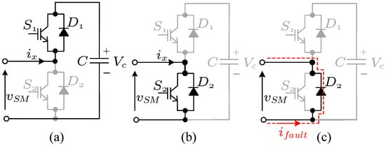
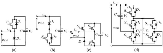
The HB-SM shown in Figure 1 represents the simplest and most common SM topology utilized in MMCs.
Figure 1.
Half-bridge SM: (
a
) connected state, (
b
) bypassed state, and (
c
) blocking state.
For protection reasons, semiconductor devices in the SM should be blocked under dc-side faults. In the case of the HB-SM and all other unipolar SMs, diodes form a conduction path from the ac to the dc side that continues to feed the fault current. Therefore, in order to isolate the converter from dc-side faults, an additional device (
for e
xample.g., DCCB) is usually necessary
[1][24].
1.1.2. The Full-Bridge Submodule (FB-SM)
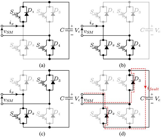
The full-bridge SM (FB-SM) is widely used as a bipolar SM, as shown in
Figure 2. Similarly to the HB-SM, it provides a positive and a zero voltage level (
Figure 2a,b, respectively), which give the FB-SM all the functionalities of the HB-SM. Additionally, the negative state of
Figure 2c can be used
[2][25] for improving the voltage/energy balancing and current control performance of the MMC
[3][26], enabling multiple harmonic injections in the MMC arm
[4][27]. FB-SMs can also be used in other converters such as the Alternate Arm Converter (AAC)
[5][28].
Figure 2.
Full-bridge SM: (
a
) positive state, (
b
) zero state, (
c
) negative state, and (
d
) blocking state.
Revisiting the dc-fault scenario, the fault current path through the FB-SM includes the SM capacitor (
Figure 2d) effectively providing the FB-MMC with dc-fault clearing capabilities. This is the most prominent feature of the FB-SM and all other bipolar SMs, as it allows the converter to operate in a dc-grid without requiring additional DCCBs. The total blocking voltage required for dc-fault is equal to the total dc-link voltage, which can be provided by half the SMs in an FB-MMC. This means that an MMC built exclusively with FB-SMs is over-designed, a conclusion which gives rise to a whole family of SMs (as discussed in the following sections) as well as many hybrid configurations for the MMC
[6][29].
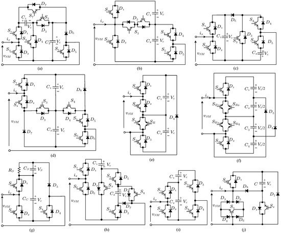
1.2. Unipolar SMs
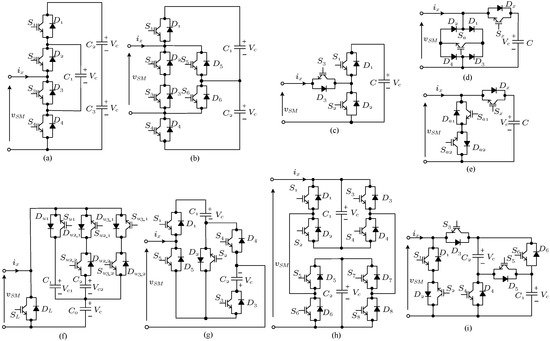
From the perspective of arm voltage generation, unipolar SMs provide identical functionalities to the HB-SM as they can only generate voltages of positive polarity. This means that any high-level controllers remain identical to the ones used in the HB-MMC and only internal (typically voltage balancing) requirements need to be considered for each SM. The unipolar SMs are shown in
Figure 3. Unipolar SMs are generally simpler in structure and some topologies can reduce the losses of the converter. However, unipolar SMs normally can offer only a subset of functions in the operation of the MMC. Furthermore, a bypass thyristor may be required for each SM or for groups of SMs to guarantee the fault tolerant operation of the converter
[7][30].
Figure 3. Unipolar SMs: (a) FC-SM—Flying capacitor SM; (b) M-ANPC-SM—Modified active neutral-point clamped unipolar SM; (c) SS-SM—Series switch SM; (d) BBSM1—Bidirectional blocking SM 1; (e) BBSM2—Bidirectional blocking SM 2; (f) SSwC-SM—Stacked switched capacitor SM; (g) 3L-SwCSM—Three-level switched-capacitor SM; (h) 3L-DSM—Three-level double SM; and (i) FTSM—Fault tolerant SM.
Unipolar SMs structures can be based on well-known multilevel converter topologies such as the flying capacitor (FC—
Figure 3a
[8][31]) or the active neutral-point clamped converter (M-ANPC—
Figure 3b,
[9][32]) providing additional voltage levels from a single SM. Similar structures have been proposed based on NPC and T-type converters, however there are challenges with balancing of the capacitor voltages at unity power factor
, as will be discussed in Section 2.5. This lack of capacitor voltage balancing makes these SMs unsuitable for HVDC applications. Addition (SS-SM,
Figure 3c
[10][33]) or substitution of devices with bidirectional switches (BBSM1 and BBSM2,
Figure 3d,e
[11][34]) result in unipolar SMs with identical behavior to the HB-SM. Such structures may provide a fault current blocking state to the converter; however, the interruption of the fault current in the main path and the lack of fault current dissipation paths can lead to substantial over-voltages and potential destruction of the SMs during a dc-fault.
Other unipolar structures include the stacked switched capacitor SM
[12][13][35,36] and the three-level switch capacitor SM
[14][37], shown in
Figure 3f,g respectively. The switched capacitor structure allows for one or more capacitors to be inserted in series to the main SM capacitor, effectively reducing the required capacitance (and energy stored in the MMC arms) for the same voltage ripple but at the cost of additional devices. The three-level double SM
[15][38] of
Figure 3h can replace two HB-SMs for the same number of devices as the FB-SM. The main advantage of this topology is that it allows for parallel connection of devices allowing for higher currents and parallel connection of the capacitors reducing the voltage ripple in capacitors, peculiarly at lower output frequencies.
1.3. Bipolar SMs
Bipolar SMs have the ability to generate both positive and negative output voltages, meaning that the total arm voltage can have two polarities. This feature provides two key functionalities to the MMC: (i) the capability of blocking and clearing dc-side faults (something that unipolar SMs cannot do and which requires a bypass structure to eliminate extreme stress on semiconductor devices in the SM) and (ii) operation in the overmodulation range by generating output voltages larger than the maximum voltage of the dc-link. These additional functionalities expand the operational envelope of the MMC, the ways it can be designed, sized and controlled as well as further extending its areas of application. Due to the number of combinations that can be used for generating bipolar SMs, the amount of bipolar circuit topologies proposed in the literature is substantially greater than unipolar ones.
The simplest implementation of a bipolar structure is the combination of a single FB-SM with one HB-SM, in what has been called as a Mix-SM or as a hybrid HB-FB converter, shown in
Figure 4a
[16][40]. Based on the analysis of Section 2.1.1 and Section 2.1.2, this implementation is straightforward and will not be analysed further.
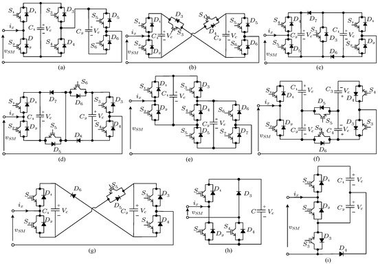
Figure 4. Bipolar SMs: (a) Mix-SM—Mix-connected SM; (b) CCSM—Cross-connected SM; (c) CD-SM—Clamped-double SM; (d) 3L-CDSM—Three-level clamped-double SM; (e) SFB-SM—Semi-full-bridge SM; (f) AFB-CCDSM—Cross-Connected Asymmetrical Full Bridge SM; (g) 3L-CCSM—Three-level cross-connected SM; (h) UFBSM—“Unipolar-voltage” full-bridge SM; and (i) SC-SM—Single-clamped SM.
A common way of implementing a bipolar SM is by combining HB-SMs through a dc-side structure that allows for positive and negative voltages to be generated. These SMs can also be seen as derivatives or simplifications of two or more FB-SMs. Examples in this category of bipolar SMs include the cross-connected SM (CC-SM)
[16][40], the clamped-double SM (CD-SM)
[17][41] and the three-level CD-SM (3L-CDSM), shown in
Figure 4b–d, respectively.
Substitution of switches to diodes reduces the controllability of a specific SM as not all voltage levels can be generated for both current directions. Vc
A variety of other bipolar SMs are shown in
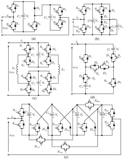
Figure 5 and include: (i) the CSM or self-blocking composite multilevel SM which is modified by two HB-SM
[18][46] and improves the voltage-balancing capability of the SM capacitors so that negative voltages are only generated during blocking states (
Figure 5a); (ii) the 4LT2C is 4-Level T-Type Neutral Point-Clamped SM which addresses the voltage-balancing issues of the three-level T-type SM with the inclusion of
S4 and
S5 [19][47]. These devices provide an additional path to control the voltage of capacitor
C1 (
Figure 5b); (iii) the T2HBSM or T-type half-bridge based SM (
[20][48],
Figure 5c); and (iv) ACTSM or Active clamped T-type SM (
[21][49],
Figure 5d) which also address voltage-balancing issues of the T-type SM with alternative current paths while providing controllable negative voltages; (v) the switched-capacitor SM
[22][50] expanding unipolar switched capacitor SMs to enable bipolar voltages; (vi) the ASM or Asymmetrical SM (
[16][40],
Figure 5i); and (vii) the AUFBSM or Asymmetrical unipolar full-bridge SM
[23][51] which, despite its name, provides bipolar functionalities through an additional capacitor, albeit reducing the scalability of the SM structure due to the unequal voltage blocking of each device; (viii) the DCBSSM or Diode-Clamped Bidirectional Switch SM
[24][52].
Figure 5. Bipolar SMs (cntd.): (a) CSM—Self-blocking composite multilevel SM; (b) 4LT2C— 4-Level T-Type Neutral Point-Clamped SM; (c) T2HBSM—T-type half-bridge based SM; (d) ACTSM—Active clamped T-type SM; (e) HDDBSM—Hybrid Double Direction Blocking SM; (f) M-HDDBSM—Modified Hybrid Double Direction Blocking SM; (g) AUFBSM—Asymmetrical unipolar full-bridge SM; (h) SwCSM—Switched-capacitor SM; (i) ASM—Asymmetrical SM; and (j) DCBSSM—Diode clamp with bidirectional switch SM.
In an effort to reduce losses in the SMs, the concept of the SC-SM (
Figure 4i) was extended to double HB-SMs; an extension that leads to two different possible configurations. The HDDBSM (Hybrid Double Direction Blocking SM) of
[25][53] uses a single diode in the blocking state to provide a current path through one of the two capacitors in the SM
[26][54]. Blocking of the current through the main circuit is provided by means of a bidirectional switch which substitutes one of the unidirectional switches of the SM. The same concept is seen in the modified HDDBSM
[27][55] of
Figure 5f which uses substitutes two devices with bidirectional switches and offers a path for the dc-side fault current via splitting capacitors and two additional diodes.
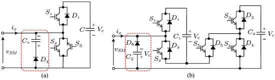
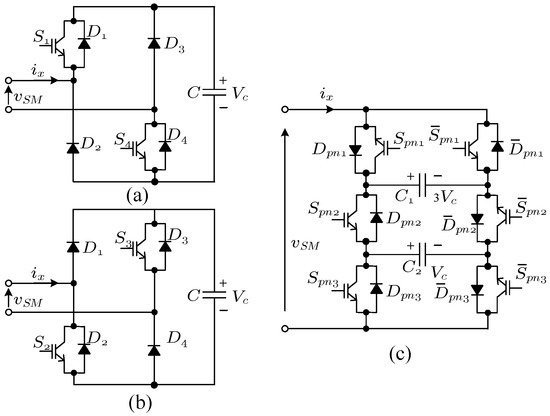
In most configurations, dc-fault blocking is provided by the main devices and particularly capacitors of the SMs. An alternative approach is that of the BBSM/RBSM (Bidirectional blocking SM/Reverse blocking SM)
[28][56] and the RBDSM (Reverse blocking Double SM)
[29][57]. These two SMs are shown in
Figure 6a,b, respectively. The main issues with such an approach are the need for an additional capacitor, which results in a substantial increase in the size of the SM, particularly in high-power applications, as well as pre-charging of the capacitors and the transient response, immediately after a fault if the auxiliary capacitor is not fully charged.
Figure 6. Bipolar SMs with bypass circuits: (a) BBSM/RBSM—Bidirectional blocking SM/Reverse blocking SM; and (b) RBDSM—Reverse blocking Double SM.
As it will be discussed later, bipolar SMs typically introduce additional semiconductor devices which leads to an increase in the overall power losses of the converter, but this increase in losses should be evaluated together with their fault clearing capacity.
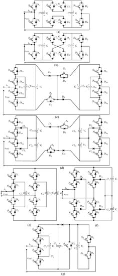
1.4. Multilevel SMs
The combination of FB-SMs and other multilevel topologies or the hybridization of multilevel converters with HB-SMs results in a category of multilevel SMs which, although have extended SM structure, can be treated similar to unipolar or bipolar SMs. These SMs include the dual FB parallel-connected SM and the dual FB (identical to the CCSM of
Figure 4b) as 5-level fully controllable SMs
[30][58] which can be seen as alternative connections of two FB-SMs
[31][59].
The 5-LCFCSM (
Figure 7c) and 5-LFCSM (
Figure 7e) are two FC-SMs
[32][60] connected on the dc-side
[33][61] either through a CD-SM structure or as a multilevel H-bridge
[34][62], while, similarly, the 5-LCNPCSM (
Figure 7d) and 5-NPCSM (
Figure 7f) are based on the NPC-SMs
[35][63]. The additional switching states and current paths can be used to address the voltage-balancing issue of the NPC-SM through an increase in the switching frequency. A hybrid combination of a FC-SM and one HB-SM
[36][64] creates the SC-FCHBSM (
Figure 7g) and demonstrates a method of generating, at least in theory, additional multilevel SMs.
Figure 7. Multilevel SMs: (a) Dual FB Parallel-Connected SM; (b) Dual FB Cross-Connected SM; (c) 5-LCFCSM—Five-level cross-connected flying capacitor SM; (d) 5-LCNPCSM—Five-level cross-connected neutral point clamped SM; (e) 5-LFCSM—Five-level flying capacitor SM; (f) 5-LNPCSM—Five-level neutral point clamped SM; and (g) SC-FCHBSM—Series-connected flying capacitor with half-bridge SM.
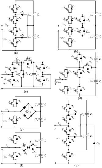
1.5. SMs with Voltage Balancing Limitations
For the steady operation of the MMC, the capacitor voltage balancing is one of the basic requirements in HVDC applications. Although capacitor voltage balancing is generally considered possible under all operating conditions, this is not always the case for certain SMs. This category includes, most prominently, SMs with neutral-point voltages such as the NPC-SM
[8][31], the T-type SM
[37][65] (both TSM1 and TSM2
[19][47]) and the ANPC-SM
[9][32]. The main reason for the reduced voltage-balancing capability is the inability to charge or discharge the two capacitors (C1 and C2) for the same time under the operation of unity power factor. Another topology with limited voltage balancing capabilities is the DCMSM (
Figure 8g), which is a modified version of the NPC-SM to provide dc-fault-blocking capability but again with limited control options over
C1[38][66]. The Asymmetrical Mixed SM (AMSM
[39][67]) and the self-blocking composite multilevel SM (CSM-1
[18][46]) also exhibit similar limitations and will not be further considered in this work.
Figure 8. SMs with voltage balancing issues: (a) NPC-SM/DC-SM—Neutral point clamped SM/Diode clamped SM; (b) ANPC-SM—Active neutral-point clamped unipolar SM; (c) CSM-1—Self-blocking composite multilevel SM 1; (d) AMSM—Asymmetrical Mixed SM; (e) TSM1—T-connected NPC SM 1; (f) TSM2—T-connected NPC SM 2; and (g) DCMSM—Double clamped diode SM.
1.6. Unidirectional SMs
The assumption that a converter does not need to operate at all four quadrants allows for further simplifications in the SM structure, mainly through the substitution of bidirectional switches with diodes. For example, the unidirectional SM (version 1 and 2 in
Figure 9)
[40][68] have a similar topology; both of them substitute one IGBT of the HB-SM with a diode. The same approach is used in the RD-SM, removing all components that are not used in unidirectional current flow
[41][69]. The combined half-bridge full-bridge SM
[42][70] has a diode instead of a switch in the terminal, which is unique and does not exist in any other SMs. As these SMs cannot meet all of the requirements for HVDC applications, they are also not considered in the analysis of the following sections.
Figure 9. Unidirectional SMs: (a) Unidirectional SM1; (b) Unidirectional SM2; (c) RD-SM—Reduced device SM; and (d) CHBFBSM—Combined half-bridge full-bridge SM.
1.7. Other VSC SMs
Some SMs that could not be included in the previous sections are briefly summarised here. The “improved” hybrid SM or IHSM
[43][71] consists of a UFBSM and a HB-SM and can be considered as a reduced functionality Mix-SM with identical switching states and functionality except the reduced control for negative voltage levels. The virtual infinite capacitor (VIC) configuration has been added in an HB-SM as VIC-SM (
Figure 10b) to provide adjustable voltage and reduced capacitance
[44][72]. As for the three-level clamp full-bridge SM (TL-CFBSM
[45][73]), two inductors are added in 3L-DSM to protect capacitors from damage due to unequal voltages. However, the switching states and blocking states do not change and can be functionally considered identical.
Figure 10. Others: (a) IHSM—Improved hybrid SM; (b) VIC-SM—Virtual infinite capacitor SM; (c) TL-CFBSM—Three-level clamp full-bridge SM; (d) MSCSM—Modified switched capacitor SM; and (e) LSM—Lattice SM.
Ref.
[46][74] introduces the Modified switched capacitor SM (MSCSM) of
Figure 10d as a dc-fault-tolerant topology, but the blocking state limits the current flow paths through the SM. Higher voltage levels from a single SM can be generated by the lattice SM (LSM
[47][75]) that can also be viewed as equivalent to four HBSMs connected in series. However, the requirement for six RB-IGBTs and the lack of an easily scalable structure reduces the benefits, considering that a fault-clearing path is also not available.
1.8. Csc and AC-AC Submodules
IFor completeness of t
was includedhe review, this section includes VSC-based SMs that have been developed for other applications. The DBSMs of
Figure 11a,b are designed as HB-SM alternatives for current-source converters
[48][76], while the Packed U-Cell SM (7L-PUC
[49][77]) uses hybrid voltage levels and unequal device ratings in a structure mostly suitable, but with many design and operation limitations, to ac–ac conversion.
These three SMs will also not be further considered for the loss analysis in the rest of this article.
Figure 11. CSC and AC-AC SMs: (a) DBSM-1—Diagonal bridge SM 1; (b) DBSM-2—Diagonal bridge SM 2; and (c) 7L-PUC—7-Level Packed U-Cells.
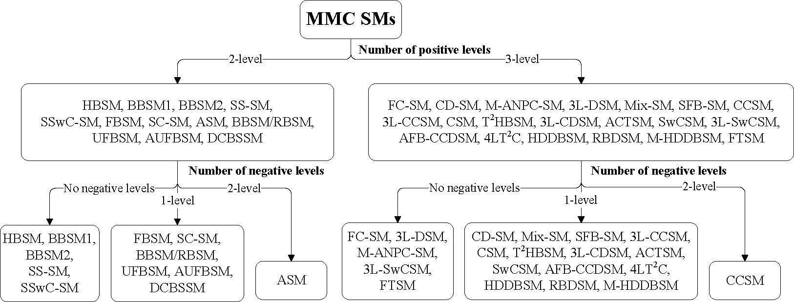
2. SM Classifications
The Figure 12 is about the timeline of SM introduction and the Figure 13 is about the classification of SMs based on number of positive and negative levels in their output voltage.
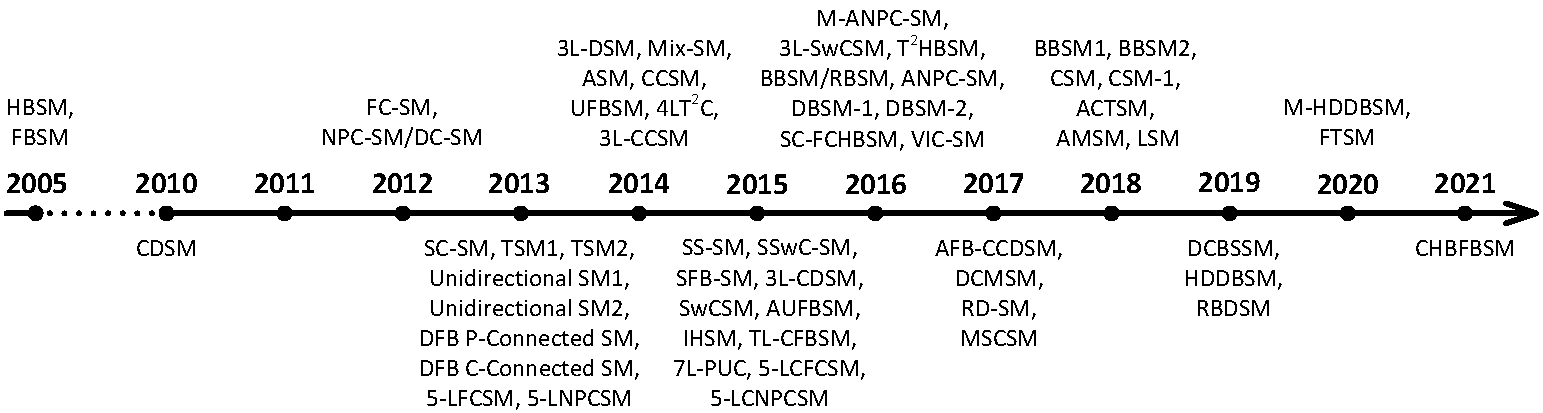
Figure 12. Submodule development timeline as of 2022.
Submodule development timeline as of 2022
Figure 13. Classification of SMs based on number of positive and negative levels in their output voltage.