Your browser does not fully support modern features. Please upgrade for a smoother experience.
Please note this is a comparison between Version 1 by Darius Muyizere and Version 2 by Vivi Li.
In the electricity grid, communication delays arise at a number of stages, which include signal transmission from phasor measurement units (PMUs) to management centers, from management centers to controllers, analog-to-digital conversion, computing on overall entry adjustable, and phase synchronization of alerts through the Global Positioning System (GPS). Such delays will have an effect on controllers and device performance.
- smart grid
- communication system
- controller
- operations
- communication delay
- mitigations
- power control system
1. Introduction
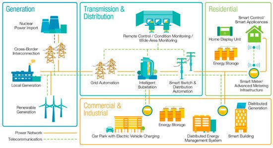
In today’s world, modern power systems are becoming more and more sophisticated in identifying and making decisions and controlling various tasks that are going to be solved in different sectors such as power generation, transmission, distribution, and consumers, couldas be found we find below in Figure 1. However, with the rise of technology in modern electricity, there is a growing trend in a structure that is changing and consists of efficient monitoring and regulation of each area of the electricity network. The functioning of the intelligence system has been shown to be reliable in combining efforts to improve the quality of information exchange.
In an electricity grid, communication delays arise at a number of stages, which include the signal transmission from phasor measurement unit (PMUs) to the manage centers, from the manage centers to the controllers, analog-to-digital conversion, computing on overall enter adjustable, and the phase synchronization of alerts through Global Positioning System (GPS) [1]. Such delays will have an effect on controllers and device performance [1]. Wide control system communication networks and information sent in the shape of a package. For the most part, in controlling the communication system, there are many time delays that come in the form of a packet such as latency, which is the time delay between the two sequential bits dispatched to its destination, although it also happens to be done in different communication modes [2].
In this connection, a request is made in support of this initiative and the development of reliable telecommunications infrastructure by establishing a strong network of broadband (WAN) for feed and customer service. WAN-based electrical equipment is based on the interconnectedness of technology in communication technology such as fiber optics, power line communication (PLC), copper-wire line, and various technologies (i.e., media communication in mobile networks such as GSM/GPRS/WiMAX/WLAN and Smart Radio). They are set up to support some monitoring/control programs such as control and information control (SCADA) /Energy Management System (EMS), Distribution System (DMS), Equipment Development System (ERP), and physical safety of equipment in large areas and broadband and capacity in closed networks.
The act of the intelligent system has been shown to be reliable in combining efforts to improve the quality of information leading to the idea of control such as relay in closing through the actual line depending on the performance of actuators, sensors, and controllers are some components of real-time communication. The other is that it is repeated in different research papers in the form of feedback. Signals are generated through a communication line to avoid costs and easy access to control, easy maintenance, and special attention is now given to the use of information technology in the control system [4].
Therefore, facilitate the supervision and regulator of electricity systems and will increase the ability to know the situation [5][6][5,6]. That is why it has been identified as one of the most important achievements of the grid, including the fact that there are many measurements and there are to communicate for control assembly as the backbone of the system. It has also been found that various measurement information, instructional signals, appeals, and up-to-date information are used among many intelligent electronic devices. Some of the papers also go back to describing the structure and size of a high-speed communication network. The amount of information from the actuators, sensors, controllers, and processes is going to focus on intelligent electronic devices (IEDs), customer advanced metering infrastructure (AMI), and distributed energy resources (DER) [7]. And it turns out that depending on the different types of components such as fiber optic communication, power line communications, and wireless technologies are the other determinants of performance, as has been the case in many studies that have been revisited in the practical use of supervisory control and data acquisition (SCADA) [8][9][10][11][8,9,10,11].
The intelligent and powerful network of systems and communications continues to be taken into account, as some differences in performance depend on the architecture, at the current level, the power grid is characterized by a cyber-physical system (CPS), which includes the physical process, sensor/actuator, network, control centers, and information that indicates the disturbance information depending on the position or function [3][8][3,8] The use of each category is possible, and information flows between all levels, as they only work together [12]. As there are delays in communication and cyber-attacks appear in many and varied ways, for example, there is a basic description of it is to use power lines and direct/indirect electricity where no network user is installed. As the various interactions of the intelligence grid include the physical, functional, and commercial complementarity through the communication network to exchange information, the attacks are larger than those listed in Table 1. However, in this table, we show the latency and the normal surface area that has the potential to be affected by modern power systems that are reviewed as a baseline to determine the domain and the type of normal attack, and as we will see later in order to take precautionary measures against the grid [8]. According to Wei L. et al. [9], the main attacks are most likely due to the technology being used, and the communication delay shows that it has a part to be counted as shown in Table 2. As exposed in Table 2, the SCADA, control system, and State estimator there is a communication delay, but you see in the attacks there are other major loopholes such as service denial of service (DoS), false data injection attack (FDIA) [8][13][8,13] robbery [14], the introduction of destructive programs or worms, and damage to the electrical system such as attacking 14 destructive devices [15].
Table 1.
| Transmission System | Distribution System | Device | System | Cyber Attack | Delay | ||
|---|---|---|---|---|---|---|---|
| Data Concentrator (DC) | √ | √ | ] | √ | (2019)FDIA | √ | |
| Random Delay | 0 to 100 | Secure the system | SCADA | √ | √ | √ | |
| ] | |||||||
| (2021) | |||||||
| Variable Delay | 50 to 100 | attenuate the influence |
Table 36.
Packet loss degree measured in different studies.
| Reference No. | Loss Rate/Loss Rate Range (in %) | |||||||
|---|---|---|---|---|---|---|---|---|
| [51][90] (2014) | 0 to 5 | |||||||
| FDIA/DOS | [47][86] (2020) | |||||||
| [45][42] | Random Delay | (2016)30 to 300 | Maintain operational stability | Control system | √ | √ | √ | |
| 20 to 70 | FDIA/DOS | [48] | ||||||
| [87] (2018) | Network-Induced Time Delay | |||||||
| [ | 0 to 700 | 52][ | Identify the distribution of time delay | State Estimator | √ | √ | ||
| 44] (2016) | 20 to 40 | [49][88] (2021) | Constant Delay | 300 and 500 | FDIA | |||
| [ | Improving the stability of the power system | |||||||
| 53 | ||||||||
| ][91] (2020) | 0.05 to 1.5 | Communication channel | √ | √ | √ | DOS | √ | |
| [40][62] (2021) | Time-Varying Delay | 100 to 500 | Increases the transfer capabilities in tie | Power market | √ | |||
| [ | 50 | √ | ]FDIA/DOS | √ | ||||
| [89 | Remote Terminal Unit (RTU) | √ | √ |
3. Compensation for Electricity-Based Communication and Network Latency
Communication delays may lead to insecurity of communication-patrol frameworks. Expanding inquiries about efforts have been committed to planning progress control strategies to overcome the impacts of network-induced delays [54][70]. In this segment, various switch strategies have been presented to compensate for the impacts of delay caused by the network within the power control framework.
3.1. Evaluations between Direct and Indirect Methods
Modeling the uncertainties, in terms of time delay, packet loss probability, queue length, and throughput is greatly highlighted to confirm that communication infrastructure remains robust under malicious attack [55][92]. So, it is essential to build an appropriate communication infrastructure. Otherwise, the system may introduce potential degradation of dynamic and static performance of the power system and result in system instability [55][56][92,93]. In LFC, due to the use of open communication infrastructure and phasor measurement units (PMU) in the wide-area monitoring systems (WAMS), communication delays have become assured and raise concerns about the system’s steady-state and dynamic response [57][55][58][61,92,94].
According to the data collected by the researchers in Table 47 with respect to the delay initiated in the control activities carried out, there are two types of delays that coincide with the power system. The first is a direct method based on the tracking of eigenvalues. However, the direct method can only solve delays in the system [59][60][95,96] and the method cannot withstand the delay [49][55][88,92]. The second and most direct method is based on H-infinity robust synthesis, Lyapunov’s unstable theory, and matrix equilibrium (LMIs) technique for controlling the delay of the controller [49][55][61][88,92,97]. Although limited, these skills can solve a variety of problems and delay those [62][63][38][64][68,75,81,98].
Table 47.
Assessments between direct and indirect methods.
| Methods | Calculation Load | Cooperativeness | Delay Type | Application | ||
|---|---|---|---|---|---|---|
| Direct | High | Low | Constant | [37][80] (2019), LFC., [60][96] (2015) WADC | ||
| Indirect | Medium | Medium | Constant and time varying | [65][99] (2020), [66][100] (2019) LFC, [63][75] (2017) LFC with DDC, [64][98] (2014) WADC | ||
| FDIA/DOS | ||||||
| √ | ||||||
| Phasor Measurement Unit (PMU) | √ | √ | FDIA | √ | ||
| Programmable Logic Controller (PLC) | √ | √ | FDIA | √ | ||
| Advanced Meter Infrastructure (AMI) | √ | FDIA | ||||
| Intelligent Electronic Device (IED) | √ | FDIA |
Recently, the suggestion that follow-up assessments are due to delays in some effects of power system levels, has been made as described in these papers [16][17][16,17]. There are also different ways to control, to evaluate the communication delay in the AGC system discussed in [18]. Security-related delayed system measurements between equipment and controller [14][18][14,18]. Heydari et al. have shown that communication in delays affects microgrid island and continue with the second inspection that took place; the survey was conducted with a small sample [19][20][19,20]. Some researchers showed one of the ways in which literature only assessed its power delayed check for the second check (e.g., [21]) and others (e.g., [22]) on the full line of the power of the system, both are small-scale signals. There are also indications of the effects of testing delays on the distribution system state estimation (DSSE) were investigated using Monte Carlo (MC) analysis in [23][24][23,24] are evaluated, using a well-defined weighted least squares (WLS) the weight of the matrix, in [25], however, to the knowledge of the authors, it has never been established as an undoubted source for growth the analytical expression for calculating the final state estimation (SE) is undoubtedly related to the shock from the communication. As Hasan Ali has highlighted in the lines of analysis in various power system activities, namely in view of the delay in communication, it has been shown to be necessary to dramatically reduce delays to secure the line to be firm. However, the practical experiences of the rope you have calm in many cases ignoring the effects of communication delays as they are categorized [26][27][28][29][26,27,28,29]. The stable security system has been restored to the role of telecommunications delays, while telecommunications delays are calculated in the diagrams [8][18][30][8,18,30].
2. Robust Telecommunications Analysis Based on the Power of the Control System and the Network Caused by the Delay and the Packet Dropout
In the study, there were many delays caused by the network [31][32][74,77]. In Ref. [32][77], four main types of delay are discussed, namely: (a) the model of constant delay. (b) the model of extreme delay. (c) the Markov chain model, and (d) the Markov model. The reasons for this type of delay are in low speed, network speed, and the protocol sent [19]. There are two types of delay, especially (i) sensor for delay controllers and (ii) controller delay for the actuator. Because network latency is due to network connectivity, it is sometimes fluctuating, unexpected, and the upper boundary is unknown. As a result, the delay caused by the network is usually done as a time delay between [33][34][69,78] and a Markov network with a known transitional probability, a probability of a partial transition, and an arbitrary change [32][77]. As declared, in reference to [35][79], network delays have been identified as a reason to undermine the functioning of the system or possibly as a reason for insecurity. In [36][37][39,80] authors proposed an algorithm based on a gradual push of money to address Electronic Data Processing in a way that is reduced to a communication network with different topology and communication latency. The proposed algorithm is allowed to solve Electronic Data Processing if different communication networks are connected together. There are some systems where communication delays can have a positive impact on system performance, as described in [36][38][39,81]. In Ref. [39][82] the authors asked for an LMI method to identify the two-way static solution provided by the gain controller to compensate for delays and a well-planned network and provide audit performance. Table 25 shows the statistical delays in the various studies conducted in the reference paper. The maximum delay to be assessed is 500 ms [40][41][62,83].
The data packet has dropped the problem and is a major issue, depending on the shipping method. Broadband and a lot of information is sent to one line responsible for this defect [36][39]. Numerous studies have examined losses in network control [42][43][44][47,84,85]. These difficulties often occur due to the exchange of information between different devices, which degrades performance and can disrupt the system. Due to the numerous vehicles, the loss of parking information is also a major concern [36][39]. Basically, the effects of dropping out of school are also known as Bernoulli or Markov. In many communication networks, various data packets are slow to arrive, providing times when the previously sent data packet can reach its destination later [45][46][42,43]. Table 5 and Table 36 show the statistical data for the loss of the pack considered in the various studies in the literature. The estimated rate of park loss is 80% in the definition [25][36][25,39].
On the one hand, in the case of the stochastic switching method, both the forces of delay due to the delay and of the power system are considered [54][67][70,101]. The ongoing interaction between the communication network and the power system is well-considered and comparable [54][70]. On the contrary, the expected system method shows the optimal value using the delayed data due to the network. This method is used more easily than before. Just as the delay in communication is not too late, it is serious that a quiet analysis method of communication based on an energy control system is essential. However, so far only a handful of cases has been reported. Therefore, research efforts are needed to conduct a reliable and reliable investigation of the effectiveness of the communication power control system.
3.2. Nonlinear Control
In addition to the adaptive self-tuning control method, there are still many important non-linear monitoring methods to address malfunctions in power systems, including the sliding mode control (SMC), fuzzy logic (FL) control method, network control (NN) methods, and hybrid system methods [54][59][70,95].
3.2.1. Sliding Mode Control
SMC is a variable structure control method that drives and then maintains the system trajectory within a particular neighborhood of a sliding surface [16][54][31][59][16,70,74,95]. Generally, there are two steps to designing a sliding mode controller.
Table 69 provides a comparison of experimental analysis of various traditional and associate classification techniques. Through the analysis of the table below, it shows the indicators of the performance of the algorithm for different power systems. We have compared different techniques, and they have different criteria in the system, for example accuracy, consistency, scalable and efficient reduction of overshoot. Many research results have shown that smart building techniques are more effective and predictable than traditional techniques. In the case of strategies such as ETDC + MPC, DOF-WADC, FLC and DOFC they are being used to assess performance, in fact, and F-scale. The comparative analysis concluded that ETDC + MPC and DOFC are superior to other techniques.
Table 69.
Comparative analysis of different algorithms.
| Techniques | Application Size | Threshold Parameters Applied | Compared with | Results |
|---|---|---|---|---|
| [77][106] SDC (2013) |
IEEE 50-generator test system | Td=0.1 s to 0.7 s f=0.1 Hz to 2.0 Hz ρ=0.0315, 0.0246, 0.016 0.0077 |
Without SDC | More time efficient and faster than without SDC |
| [78][107] DD-WADC and DOF-WADC (2016) |
IEEE benchmark system (WADC) | Td=800 ms to 250 ms f=0.5777 Hz ρ=0.0152 |
PC-WADC | More time efficient and faster than PC-WADC. Even under the effect of the time-varying delay of the wide-area communication network, it knows how to still maintain a good damping performance. |
| [79][108] BA and BESS (2019) |
Java 500 kV Indonesian grid (WAMC) | Td=100 ms to 700 ms f=0.6567 Hz ρ=0.0569 |
POD and BESS | Higher accuracy and faster than BESS, highly competitive with POD and BESS |
| [1] FLC (2019) |
IEEE nine bus power system (WAMS) | Td=0 ms to 700 ms f=0.5777 Hz ρ=0.0152 |
MPM | More consistent and highly effective at classification and has minimized the impact of delay in positioning on the power structure of the Hybrid system. |
| [80][109] DOFC (2021) |
Four Machine Two-Area Power System (WADC) | Td=100 ms f=0.6567 Hz ρ=0.0823 |
PID | Better performance than PID, Execution time is less. |
| [40][62] ETDC + MPC (2021) |
Kundur’s 2-area test system (WAMS) | Td=100 ms to 500 ms f=0.598 |
- Step 1: Describes the switching work: the switching work is planned to protect the framework while sliding in a dynamic manner.
-
Step 2: Define a switched control law: the switched control law is designed to move the framework state vector to the sliding mode and maintain it once it arrives.
Sliding mode control has proven to be an efficient approach to compensate for power systems [54][70]. To compensate for the delay in communication, SMC monitoring is based on broad areas and has been monitored to ensure that WADC does not misinterpret communication delays [68][54][52,70]. In terms of latency indefinitely, it was discovered that residing on a slippery slope due to the lower and upper slopes causes endless delay [69][102]. Only fuzzy control measures have been taken, except for the fuzzy-based integral sliding mode load frequency control system (FISMLFC) which is required for many parts of the integrated Wind Farming (WF) system [26][59][26,95].
3.2.2. Fuzzy Logic Control
Planning an FL controller incorporates three stages:
-
Step 1: Fuzzily (Make membership work): this step includes mapping numerical input parameters to fuzzy factors for a characterized membership work.
-
Step 2: Indicate the run the show table: this alludes to making a run the show table to determine all combinations of input signals and compare output signals for these input signals.
-
Step 3: Defuzzily the outcomes: it includes, producing numerical input values which can be utilized as control inputs of a control framework, based on the outputs of the fuzzy rules.
FL controllers are broadly utilized to handle vulnerabilities in control frameworks. In [63][75], an FL wide-area damping control with moving membership capacities is proposed to compensate for the expansive latency included within the transmission of wide-area estimation signals. In [70][31], both time delay and uncertainties in measurements in the fuzzy type-2 WADC [70][31]. In [71][103], a new direction was established by the T-S Fuzzy Control System (TSFC) and the delayed separation time in many parts of the system is applied for the load-frequency control of a three-area electrical interconnected power system to enhance the system stability under uncertain disturbances [54][59][70,95].
3.2.3. Neural Network Control
Understanding an artificial issue without a numerical demonstration of a real framework, as it were, by utilizing the interconnects between the neurons within the various layers of each framework is part of planning a NN controller. Association of neurons can be modified in its structure to clearly demonstrate the relationship between input signals and their valid fields. Learning gives NN controllers the capacity to infer subjective straight or nonlinear mapping [72][66]. Because of this feature, NN-based control can be used to improve the resilience of control frameworks and address communication link weaknesses. The use of NN-based wide-area damping controllers to adjust for a wide range of communication delays was investigated in [73][104]. Wang S. et al. [74][71], neural network approximate-based feedback adaptive quantized control protocol based on k-filter observer is proposed to reduce the estimated error and external disturbances resulting from multi-machine excitation system.
3.2.4. Comparisons of Remuneration Approaches
Table 58 summarizes a comparison of these control strategies utilized to compensate for network-induced delays in communications-based frameworks within the literature. As can be seen from the table, the nonlinear control strategy is generally autonomous of the framework shown and has high robustness to parameter vulnerability and unsettling influences, particularly ETDC, MFAC, and NN. Be that as it may, due to the plan of these controllers, preparing the LKF, FL, and NN controllers involve a huge sum of estimation information. Planning H2/H∞ , SMC, and other model-based strong controllers are moderately direct but have constrained vigor to parameter instability compared to non-linear controllers. Luckily, most of these controllers can be utilized to compensate for both deterministic and arbitrary arranged delays. As for the structure, these recompense strategies have been connected within the interconnected electricity framework control, such as WAMS, WAC and WAMC, whilst their purposes in microgrids are right now within the infants as most of the current microgrids are still in-lab demonstration projects and have not been broadly connected within the real world. In any case, the functions of these manipulation techniques in microgrids vitality administration and manipulation have been drawing in quickly expanding consideration as the critical requirement for smart networks around the world.
Table 58.
Evaluations between direct and indirect methods.
| Hz |
| ρ |
| = |
| 0.0205 |
| SPB + MPC |
| More accurate, scalable and efficient reduction of overshoot (about 39%) implies less stress over the thermal limits and less impact of isolation due to protective actions. |
| Detail Modelling Techniques | Model Dependence | Robustness | Design Difficulty | Delay Type | Applications | Main Contribution |
|---|---|---|---|---|---|---|
| (2016) (MPC) and Smith predictor-based controller | Low | Medium | Low | Deterministic and random | [75][55] Microgrid | Stability analysis based on small-signal |
| (2016) H2/H∞ synthesis controller | High | Low | High | Deterministic and random | [57][61] WAMS | Considers model of time delays |
| (2018) LKF | High | High | High | Deterministic and random | [22] WAPS | Stability analysis |
| (2018) LMIs | Medium | Medium | Medium | Deterministic and random | [33][69] WADC | Optimization-based information sharing |
| (2019) Sliding mode control (SMC) | High | Medium | High | Deterministic and random | [16] Microgrid | Stability enhancement |
| (2020) Fuzzy logic | Low | Low | High | Deterministic and random | [58][94] WAMS | Calculate delay margins |
| (2020) T-S Fuzzy control (TSFC) | High | Medium | High | Deterministic and random | [62][68] LFC | High Stability system |
| (2016) Model-free adaptive control (MFAC) | High | Medium | High | Deterministic and random | [46][43] WADC | Calculate delay margins delays Scenarios. |
| (2021) Enhanced Time Delay Compensator (ETDC) | High | High | High | Deterministic and random | [40][62] WAMS, WAC, WAMC | Calculate reduction of overshoot (almost 39%) |
| (2021) Analytical approach and Optimal control gain | Medium | Low | High | Deterministic and random | [76][105] WAMSs | Design robustness of a small-signal stability |
| (2021) Neural network control and new Fractional-Order Global Sliding Mode Control | Medium | High | High | Deterministic and random | [74][71] LFC, [21] multi-area power system LFC | Compensate approximation error and The stability and stabilization |