An exhaustive summary of the design concept, performance aspects, and fabrication methods of the micro electromechanical system (MEMS) inertial switch is provided. Different MEMS inertial switch studies were reviewed that emphasized acceleration directional and threshold sensitivity, contact characteristics, and their superiorities and disadvantages. Furthermore, the specific fabrication methods offer an applicability reference for the preparation process for the designed inertial switch, including non-silicon surface micromachining technology, standard silicon micromachining technology, and the special fabrication method for the liquid inertial switch. At the end, the main conclusions of the current challenges and prospects about MEMS inertial switches are drawn to assist with the development of research in the field of future engineering applications.
- MEMS
- inertial switch
- threshold
- sensitive direction
- contact effect
- fabrication
1. Introduction
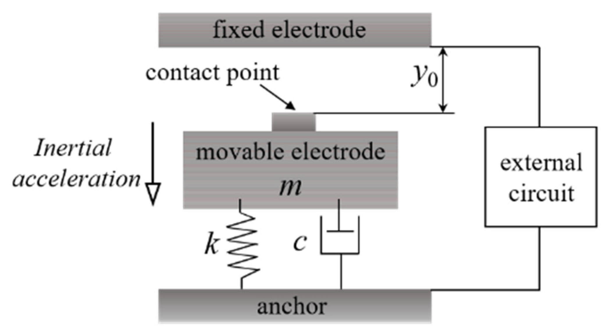 Figure 1. Schematic diagram of the spring (k)–mass (movable electrode m)-damping (c) system model of a uniaxial inertial switch. y0 means the initial distance between the movable electrode and the fixed electrode.
2. Intermittent Inertial Switches
2.1. Sensitive Direction
2.1.1. Uniaxial Inertial Switches
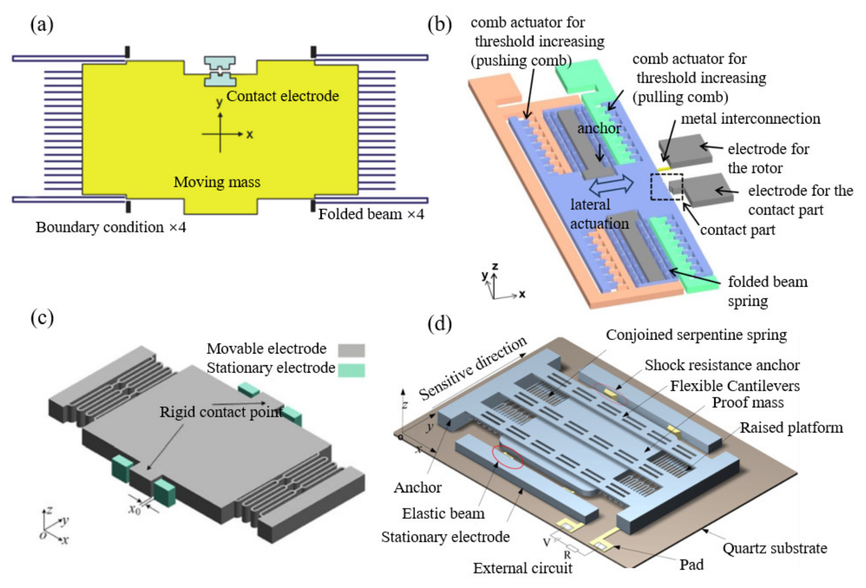 Figure 2. Some uniaxial inertial switches: (a) [
2.1.2. Biaxial Inertial Switches
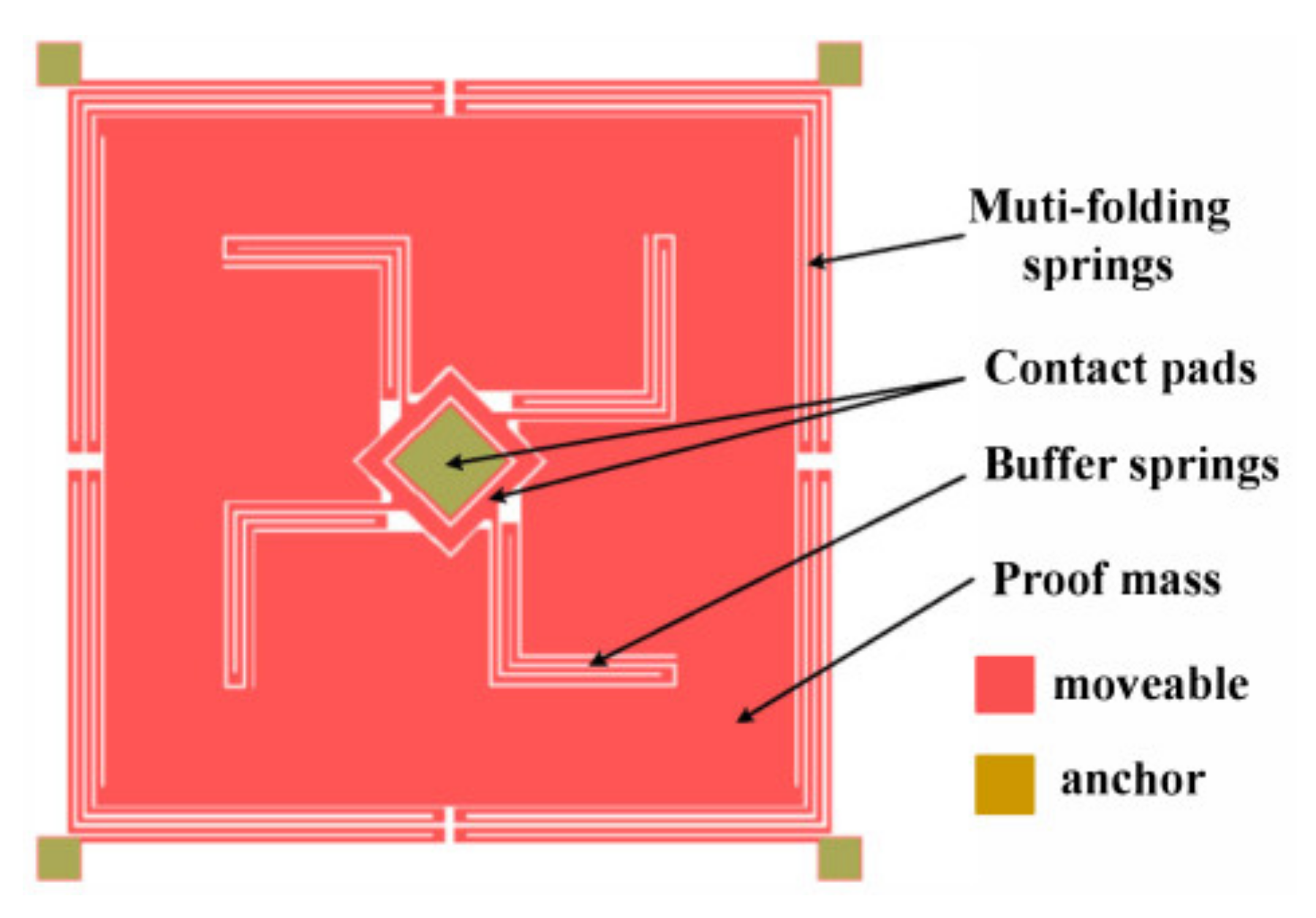 Figure 3. Schematic of the two-axis low-g inertial switch.
2.1.3. Triaxial Inertial Switches
2.1.4. Multidirectional/Omnidirectional Inertial Switches
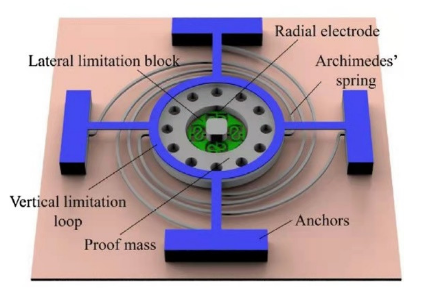 Figure 4. Structural sketch of the omnidirectional inertial switch.
2.2. Threshold Acceleration
2.2.1. Low-g Threshold Inertial Switches
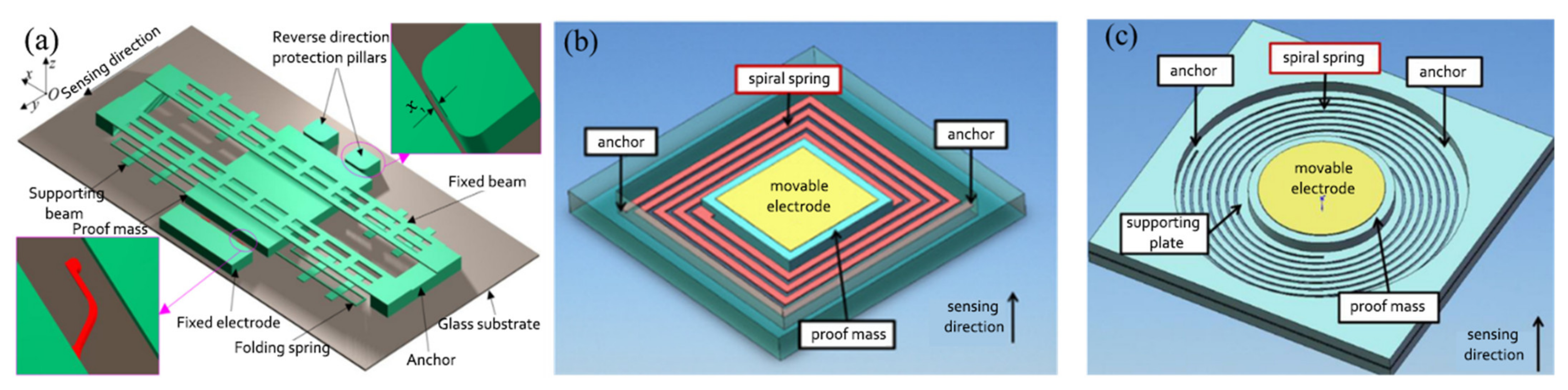 Figure 5. Schematic diagrams of three low-g inertial switches. (a) The nickel low-g MEMS inertial switch [
2.2.2. High-g Threshold Inertial Switches
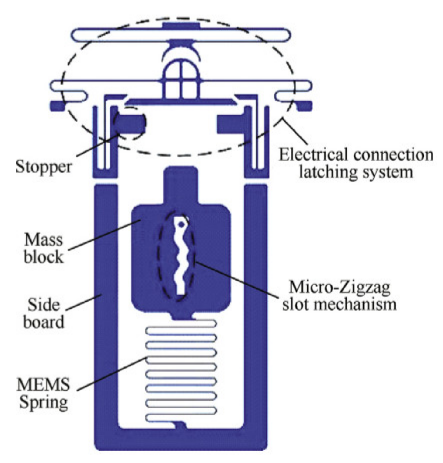 Figure 6. Schematic diagrams of the MEMS inertial high-g switch.
2.2.3. Threshold-Tuning Inertial Switches
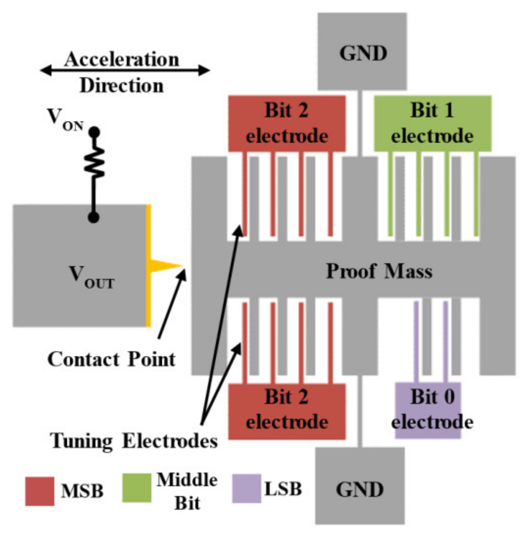 Figure 7. Simplified schematic view of a 3-bit digitally operated MEMS switch.
2.3. Contact-Enhanced Inertial Switches
Solid–solid rigid contact can easily cause contact bounce, making it unsuitable for small signal switches. It also causes arcing and welding of the contacts, resulting in contact surface damage and material transfer. This contact degradation restricts the reliability and longevity of these devices. Avoiding solid-to-solid mechanical contact means there are no issues associated with contact bounce or contact degradation, thus extending the life of the switch.
Contact time is a critical property for an intermittent inertial switch in some application environments because the longer contact time, the less difficult the signal processing is. A short contact time requires an external circuit with higher signal identification performance [3]. Insufficient contact between two electrodes is usually caused by a rigid contact process, resulting in a strong rebound of the movable electrode after touching the fixed electrode (usually a rigid substrate for conventional inertial switches). These switches have extremely short contact times (less than 10 μs), which is difficult for the external circuit to recognize [1]. Furthermore, contact bounce can damage the interface between the two motors due to mechanical hammering and arcing, subsequently affecting the durability of the system, which may result in permanent adhesion between the two electrodes [73]. In recent years, in order to eliminate the bounce phenomenon and enhance the contact effect of the intermittent switches, considerable efforts have been put into inertial microswitches. The methods mainly include some special structures and flexible materials.
2.3.1. Special Structures to Extend Contact Time
Cai et al. [1] developed a new double mass–spring system that is completely different from the traditional system design. In addition to the proof mass–spring system, instead of being rigidly fixed to the proof mass, the contact point was suspended in the middle of the proof mass by an inner spring. The experiment results demonstrate that the threshold acceleration of the MEMS inertial switch was about 175 g and the contact time of the contact point was 56 μs. The steady turn-on time of more than 50 μs was much longer than the 12 μs in the research [74]. The switch was driven vertically and the elastic beam above the proof mass block could be used as a fixed switch electrode. However, there were two switch-on signals under an acceleration of 200 g acceleration, which would lead to secondary closure of the switch and have a bad effect on the reliability of the switch. Wang et al. [5]proposed a new type of L-shaped flexible cantilever fixed electrode, and long contact was possible in a transverse MEMS inertial switch. The sensitive mass was suspended by two pairs of conjoined serpentine springs as the motion electrode and the fixed electrodes were suspended from the blocks. The flexible cantilever electrode could realize a flexible deformation to enhance contact time and avoid the rebound phenomenon of the MEMS inertial switch. The contact time was extended to 1050 μs, which was much longer than the time without cantilever buffer effect of 5 . Moreover, according to the characteristics of the cantilever arm, its special elastic deformation could be designed to realize the control method of switch contact time. With the increasing acceleration, the contact time also decreased until it tended to a stable value. At the same time, based on the same inertial switch structure, Chen et al. [3] analyzed the influence of the applied acceleration loads on contact time. Combining the tested results, it was concluded that as the pulse width of the applied shock load increased, so did the contact time. Yang et al. [32] investigated an inertial microswitch with bridge-type elastic fixed electrodes for prolonged contact. Specifically, they designed two parallel perforated elastic beams as fixed electrodes. The microswitch was equipped with a relatively good contact effect, but the switch could be triggered with an effective contact of only 12 μs when 100 g acceleration was applied. By adding a group of cantilever beams on the mass block as the buffer between the electrodes , the contact time could be prolonged and the phenomenon of jumping contact could be avoided. Another advantage of this is that the contact time of the microswitch could be extended to 240 μs. It was more than 15 times that of a microswitch without cantilever beam. In addition, Yang et al. [33] also discussed three other devices with different structures (types II, III, and IV), as shown in Figure 8. Types II and III used a cross-beam stationary electrode to realize a long contact time with deformation. The contact times for the two switches (types II and III) utilizing beam deformation were 20 μs and 30 μs, respectively. However, due to the limitation of deformation, the contact effect of the switch was not effectively improved. Therefore, type IV adopted a double spring–mass system, which greatly improved the contact effect. The experimental results show that the contact time was about 55 μs, which greatly enhanced contact performance. Xu et al. [6] introduced a laterally actuated inertial switch. As a moving electrode, the sensitive mass was connected to two L-shaped elastic cantilever beams. The switch had an inductive acceleration threshold of 288 g with a contact time of 150 μs.
2.3.2. Materials and Assistive Force to Extend Contact Time
Unlike the inertial switches described above with specific structures to increase contact time, some studies have proposed the use of special materials or external assistive forces to improve contact characteristics. Lee et al. [75] proposed a new inertial microswitch. Its contact mode was carbon nanotubes (CNTs) in contact with carbon nanotubes. Due to the high mechanical flexibility and elasticity of CNT material itself, it was prone to elastic deformation when used as contact pad material [76], so the contact time was prolonged. At present, the contact time of the existing traditional switch is only 7.5 μs, but with this inertial micro switch, the contact time could be extended to 114 μs. The results show that the new inertial microswitch proposed by Lee et al. could significantly prolong the contact time. Yang et al. [77] developed an inertial microswitch with polymer metal composite as a fixed electrode. It not only had the characteristics of multidirectional features and high sensitivity, but also prolonged the contact time of the switch and improved the stability and reliability of the inertial microswitch. The contact time was improved to 110 µs, which was longer than that one without polymer (~65 µs). In addition, an inertial microswitch with a flexible carbon nanotube/copper (CNT/Cu) composite array layer between movable and fixed electrodes was designed in [78]. The interaction between carbon nanotubes, i.e., adhesion, was one of the main reasons for the extension of contact time. Li et al. [79] designed a MEMS inertial switch to prolong the contact time through electrostatic assistance and multi-step pull action. Through the test, the contact time was about 540 μs and showed no bounce.
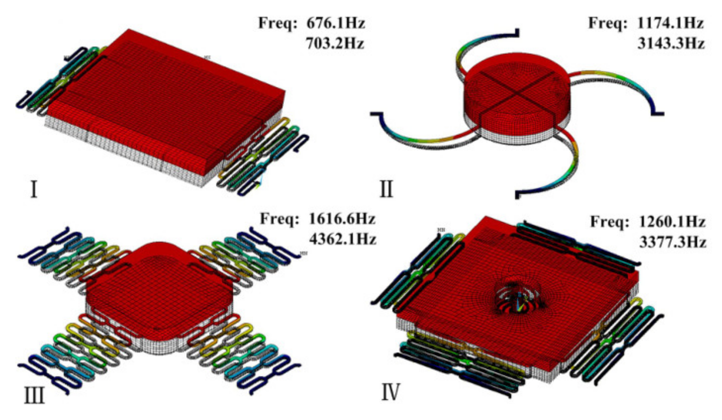 Figure 8. Modal analysis of various microswitches and their first two frequencies. Type I adopted a vertically driven structure with low off-axis sensitivity. Type II and III used a fixed contact point on the proof mass. Type IV realized a longer duration contact with a movable contact point.
3. Persistent Inertial Switches
Compared to an intermittent inertial switch without a self-locking function, a persistent inertial switch can achieve a stable contact property with a mechanical lock and a bistable structure. Furthermore, a fluidic MEMS inertial switch can also accomplish a locking function when flowing liquid (as a movable electrode) contacts the metal fixed electrode.
3.1. Latching Switches
When the acceleration increases to the threshold of the inertia switch, the mass will move and pass through the hook. When the acceleration is slowly reduced to 0, the latching mechanism prevents the proof mass from returning to the initial state. Then the switch stays in an “on” state. Lee et al. [80] introduced a hooked latch to an electrode for the contact part, which improved the reliability of the contact. The power consumption directly affected the practicability and reliability of the sensor system. An analog front-end is required to detect and interpret the output in the present commercial application of accelerometers. It leads the power consumption to be in the range of hundreds of µW to a few mW. Reddy et al. [81] developed a MEMS passive impact sensor that could be applied to multiple thresholds and had a good latch device. It could measure an impact in the range of 20–250 g at a threshold 10 times higher than itself. Ramanathan et al. [82] designed a new MEMS inertial switch design framework. The mass block was mainly supported by a group of four folded beams and it could design the accelerometer according to the parameters input by people. It was verified that the optimal threshold acceleration of the framework was about 60 g. Guo et al. [22] presented a latching switch with an easy-latching/difficult-releasing (ELDR) latching mechanism and cylindrical contacts. The ELDR locking mechanism could reliably lock the switch. The measured latching shock was over 4600 g and the response time was less than 0.2 ms. Currano et al. [83] discussed a MEMS inertial switch that was used to monitor the shock event over a specified threshold level with a latching mechanism. However, introducing a latch structure led a recovery issue, which is not beneficial to early testing and unlocking. Therefore, Zhang et al. [84] designed a novel heterogeneous integrated inertial microswitch with an adjustable acceleration threshold that could get the switch to keep a stable “on” state due to the pull-in phenomenon of a predefined bias voltage. Besides, the switch was easily unlocked by removing the bias voltage.
3.2. Bistable Inertial Switches
Additionally, the concept of a bistable mechanism has been brought to micro-inertial switches [85][86], which utilizes a bistable post-buckling structure to achieve a similar latching function. Taking advantage of the ability of the bistable mechanism to maintain two bistable positions without consuming power, the bistable structure has great superiority in designing an inertial switch with a self-locking function. Sandia National Laboratories presented a fully compliant bistable microswitch with a tapered beam in [87] and a three-segment bistable inertial switch [23] consisting of a large mass suspended on the four bistable beams, which could achieve the on-off function of a high g-value acceleration. Bistable microstructures as nonlinear elastic spring elements to precisely define two static stable states have been involved [25]. However, bistable structures have not been used to decrease the contact resistance. To reduce the contact resistance, a novel magnetic actuated bistable acceleration switch was proposed in [26], which included an asymmetric bistable mechanism with a parallel beam and three magnets arranged three-dimensionally. Zhao et al. [88] presented a wireless inertial microswitch incorporating a bistable flexible mechanism. When the bistable structure underwent buckling deformation under an excitation of external acceleration, the proof mass at the contact position could be stabilized. Liu et al. [89] studied a novel low-g MEMS bistable inertial switch with dual self-locking functions under an 8 g acceleration and reverse unlocking under a 105 g acceleration threshold, which was expected to carry out the reuse of the switch. The schematic of the designed bistable inertial switch is shown in Figure 9. This switch used a fully mechanical structure to greatly improve the anti-electromagnetic interference ability.
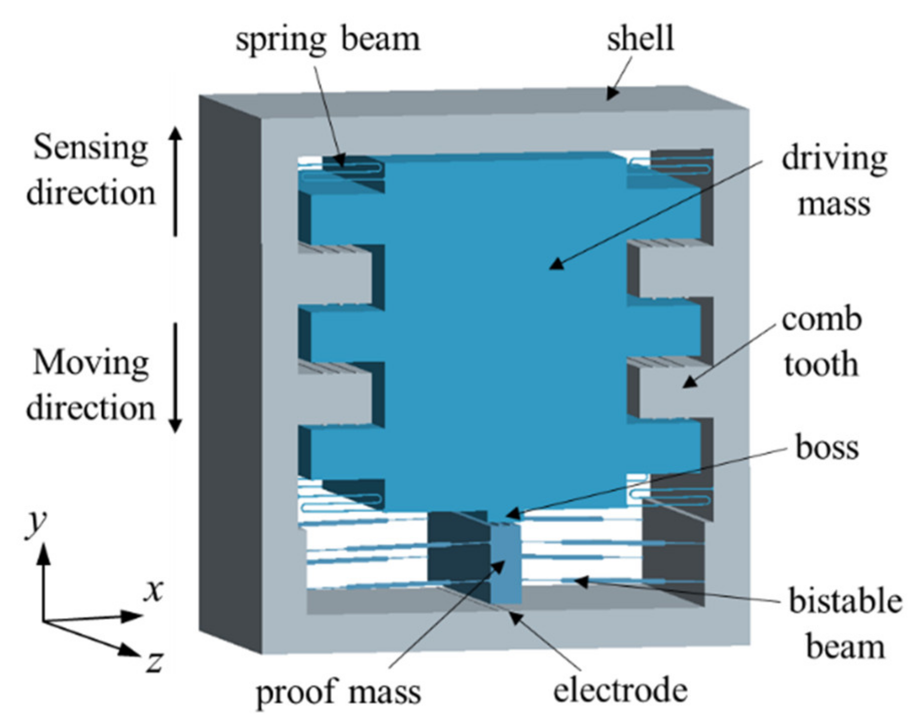 Figure 9. Schematic and structural parameters of the designed MEMS bistable inertial switch.
3.3. Liquid Inertial Switches
Unlike the conventional solid-to-solid-type micro inertial switch, a liquid inertial switch realizes contact through liquid–solid mode so as to improve its stability. The liquid–solid contact-based liquid switch mechanism can avoid problems such as signal bounce and contact wear during switch movement. Moreover, a liquid–metal (LM) microswitch [90] has been used in safety and arming (S&A) applications for time-delay fuses.
Yoo et al. [91] designed an inertial switch with a liquid–metal contact method, which greatly improved the stability of the switch contact. Kuo et al. [28] designed a passive inertial switch and integrated an L-C resonator to realize wireless signal transmission. The working fluid was water. In another design [92] introducing multiwall carbon nanotube (MWCNT)-hydrogel composite material, they proposed a liquid-type inertial switch integrated with a passive inductor/capacitor (L-C) resonator. This switch could achieve various threshold levels of acceleration by various channel configurations. Huang et al. [27] designed a microfluidic time-delay switch. The device consisted of glycerol (as the working fluid), a microcapillary valve (as the time-delay mechanism), and sensing electrodes. The schematics are shown in Figure 10. By changing the geometric design of the microfluidic system (such as channels and valves), the delay time of the microfluidic switch could be easily adjusted. The experimental test showed that the delay time range of the switch was 4.1 to 10.9 s.
Nie et al. [29] developed an innovative microfluidic inertial switch structure. It had the characteristics of accurate delay response. The results showed that the actual delay time was 114.1 ms under an inertia load of 75 g. Most studies used mercury as a conductive metal liquid, but it is toxic. Gallium indium (EGaIn) was used as the conductive element of the mobile electrode, which had the obvious advantages of non-toxicity, low viscosity, and high conductivity. Shen et al. [30] designed a self-recovery inertial switch, and its working liquid was a gallium-indium (EGaIn) metal droplet. The switch employed a U-type microchannel in order to reduce air resistance in the microchannel. There were sensing electrodes in the rectangular microchannel. After the acceleration signal disappeared, the droplet returned to the reservoir. This demonstrated the automatic-recovery characteristic of the switch. Liu et al. [93] used Galinstan and designed a microfluidic inertial switch. The test results showed that the response time was 0.66 ms and the contact time was 0.88 ms under a 51.2 g acceleration threshold. Liu et al. [31][94][95] conducted further research on the LM switch. An increase in the contact angle would increase the viscous force of the droplet on the capillary valve, thereby prolonging the response time. Furthermore, the switch structure introduced a two-stage microvalve, which facilitated adjustment of the threshold by changing the mercury volume. Huh et al. [96] designed a dual-axis accelerometer based on a liquid–metal droplet. The movement of droplet was leaded by the induced inertial force. Then they proposed an opposite design [97], which was to etch the cone-shaped guiding channel on the upper cover. The droplet was located in the channel. The switch could sense the acceleration signal in the range of 0–1 g, with high resolution and long service life.
The droplet used in the switch was selected according to its density, toxicity, melting point, and other characteristics. However, because liquid metals are volatile, the sealing problem of the switch requires special attention. Fluid is greatly affected by temperature, and cannot be kept constant at different temperatures. Therefore, the applications of fluid switches are seriously limited.
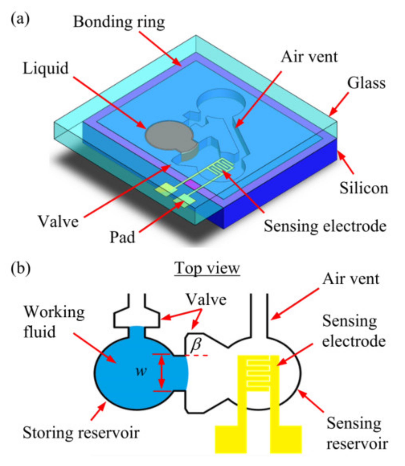
Figure 10.
Schematics of the proposed microfluidic system design: (
a
) the S-A device and (
b) top view of the device.
) top view of the device.
4. Typical Fabrication Methods
The design and fabrication method can directly affect the reliability of MEMS inertial switches, especially the lifetime, robustness, and stability under extreme conditions of shock temperature, humidity, chemical exposure, or other challenges. Depending on the design and materials of the inertial switch, fabrication methods can be divided into three categories: (1) standard silicon micromachining technology, (2) non-silicon surface micromachining technology, and (3) the special fabrication method for liquid inertial switches.
4.1. Standard Silicon Micromachining Technology
Standard silicon micromachining is mainly manifested as a combination of bonding and deep eclipsing technologies to pursue large mass, stress reduction, and three-dimensional processing. Direct silicon bonding is completed by heating to promote the polymerization of hydrogen bonds to generate SiO2, so the surface treatment of the silicon wafer before bonding is key to making the surface of the silicon wafer absorb more OH-. Besides, gold–gold thermocompression bonding has been used in the preparation of bistable inertial switches to obtain a mass block of large thickness [89].
The main process of the standard silicon micromachine is sketched as follows and illustrated in Figure 11.
(1) SOI wafer preparation: A BOE rinse is performed to remove the native oxide layer on the SOI wafer.
(2) Thermal oxidation: An SiO layer is grown and patterned, which serves as the etching mask layer for deep reactive ion etching (DRIE).
(3) Oxidation pattern: A thin layer of Al2O3 is deposited on the SOI device layer via atomic layer deposition. Then the Al2O3 film is patterned as a hard mask for a silicon etch.
(4) Device layer etching: The inertial switch silicon skeleton is then formed in the SOI device layer via silicon dry etching.
(5) Backside lithography: Backside etching is carried out, followed by long DRIE technology, to remove the handle layer underneath the device and avoid any potential stiction issues for the large proof mass. Other Bosch technology is acceptable to ensure the verticality of the etching.
(6) Moveable electrode: The moveable electrode (Ti/Pt/Au) is deposited on the back side.
(7) Back side of the proof mass: Another DRIE process is applied to reveal the back side of the proof mass.
(8) Microswitch release: The MEMS switch is finally released after removing the excessive SiO2 layer in the BHF solution.
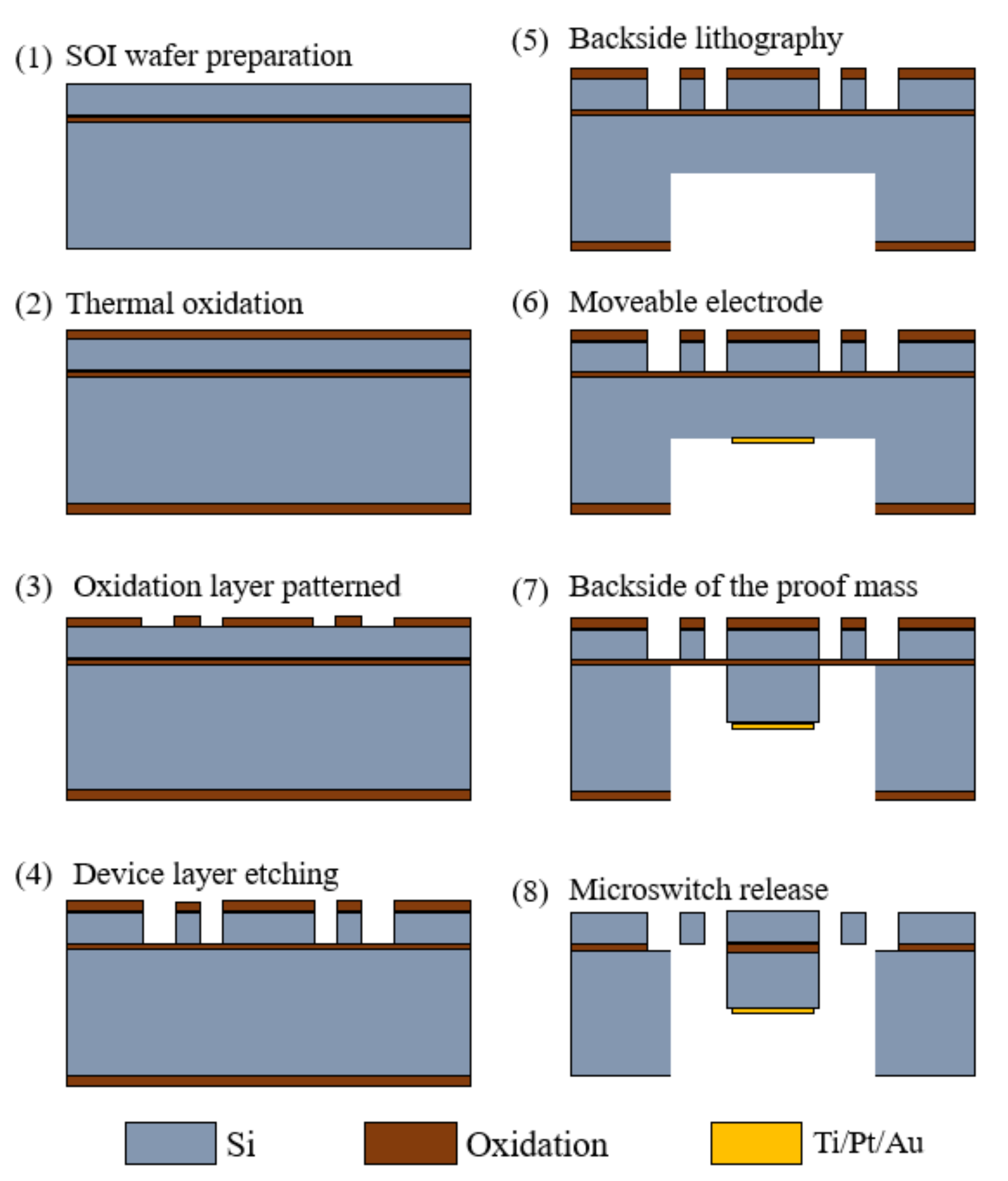
Figure 11.
Schematic view showing the fabrication process of a standard silicon micromachine.
4.2. Non-Silicon Surface Micromachining Technology
Non-silicon surface micromachining technology on a different substrate such as silicon, metal, and glass, etc., mainly includes sputtering, electroforming, and sacrificial layer technologies. Some typical new inertial microswitches, including vertical [1] and lateral actuation [3], uniaxial [35], multiaxial [4], and omnidirectional sensitive [19] and flexible electrodes using CNT/Cu composites to enhance contact [78], are fabricated by this technology.
The following is a summary of the surface micromachining process of a MEMS inertial switch combined with the preparation of a uniform omnidirectional sensitivity inertial switch. The main procedure is sketched in Figure 12 and described as follows:
(1) Preprocessing of the substrate: The roughness of the substrate surface is reduced via polishing techniques and by cleaning.
(2) Photoresist lithography: A spin-coating photoresist on the substrate and photolithography are carried out. Mostly, negative photoresist (SU-8) and positive photoresist [6] are used for the mold and sacrificial layers, respectively.
(3) Micro electroforming: As the structure material, electroplated metal nickel (Ni) has good mechanical properties and can effectively solve the problem of switch breakage under a high acceleration impact. Volume error can be reduced by controlling the plating time.
(4) Seed layer: Sputtered Cr/Cu on the substrate is used as a seed layer for device electroplating.
(5) Multilayer repetition of micro electroforming: Multilayer plating technology can overcome etching difficulties of a high slim ratio of inertial switches.
(6) Microswitch release: The photoresist and seed layer are removed, and then the inertial microswitch can be obtained. Usually, acetone or boiled inorganic are used to remove negative photoresist SU-8 and an ammonia/peroxide solution is used to remove the seed layer.
(7) Rinsing and drying the device: The released microswitch is rinsed with isopropyl alcohol or deionized water, and then dried to avoid stiction.
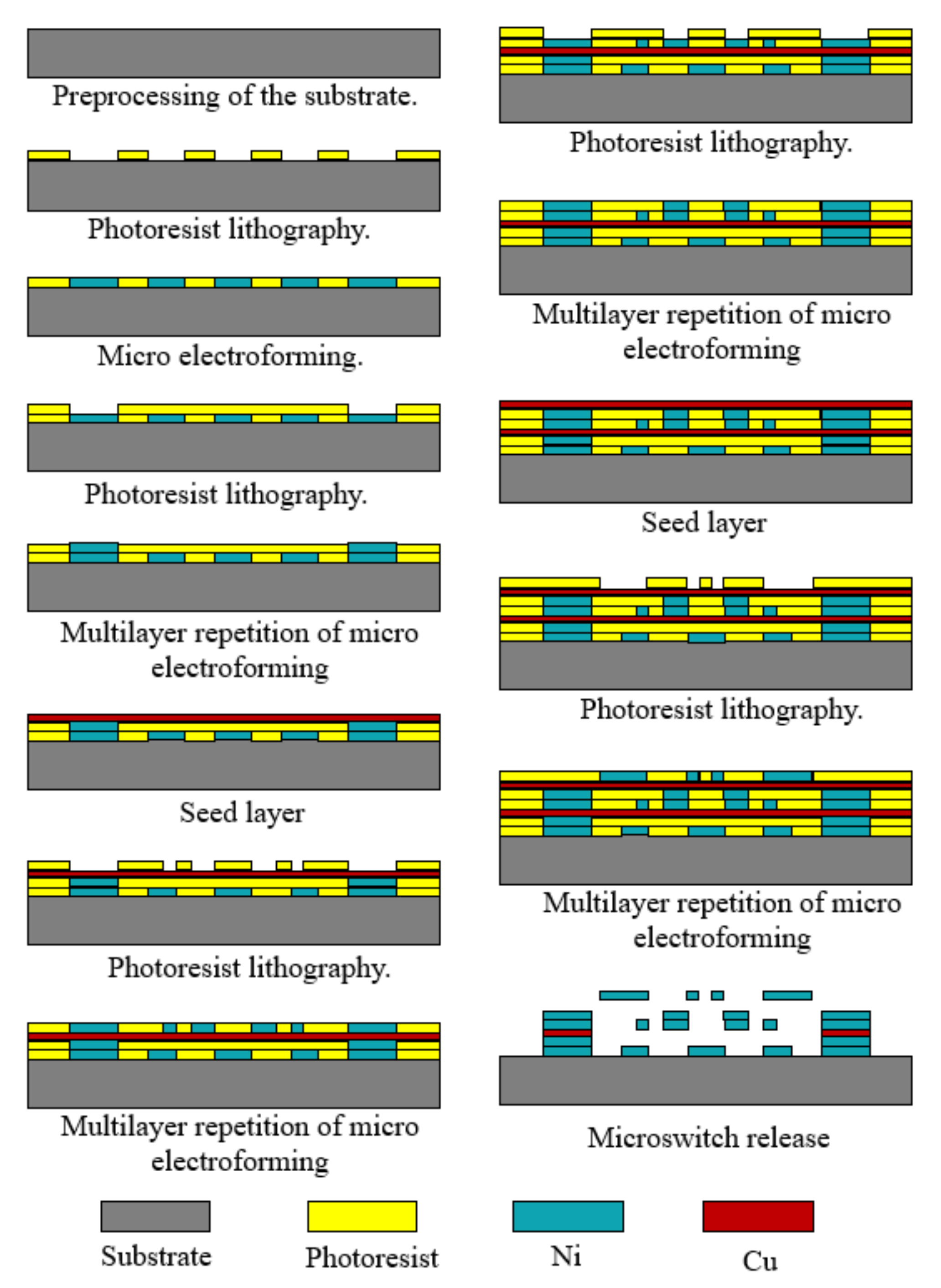
Figure 12.
Sketch of the main fabrication process of surface micromachining.
4.3. Special Fabrication Method for Liquid Inertial Switches
For liquid inertial microswitches, the key difficulty in the fabrication process is the problem of the tightness of the liquid electrode (movable electrode). Micro-channels are formed on a silicon substrate by microfabrication technology, and the covered glass substrate is convenient for observing the movement of droplets. The specific fabrication process is illustrated in Figure 13 and expressed as follows.
Microchannels with different cross-sections can be etched by micromachining processes. The silicon wafer is etched by DRIE technology, and the bonding between the silicon wafer and the glass cover is realized by anodic bonding.
(1) Silicon substrate photolithography: The microchannel is SOI material, with a photoresist masking pattern for ICP etching microchannels on the SOI material.
(2) Silicon substrate ICP etching: The microchannel is etched by ICP technique, and then the photoresist is removed.
(3) First metal electrode layer: The photolithography, sputtering, and lift-off techniques are applied on the glass substrate. The first metal electrode layer is achieved on the glass.
(4) Second metal layer: The same technology as above is used to achieve the second metal layer on the glass substrate.
(5) Glass cover plate laser drilling: To achieve the adjustment of the volume of the flowing droplets, the adjustment holes and channels are laser etched.
(6) Anode bonding and dicing: After wafer-level packaging, chips are obtained through precise dicing technology.
After completing the structural preparation of the fluid switch, the droplets are injected into the adjustment hole and the channel is adjusted to make the droplet enter the initial position. Although gold has good conductivity, its application is limited due to its high solubility with mercury. Therefore, chromium (Cr) can be chosen as the electrode material due to its proper electrical conductivity and low solubility with mercury. In addition, the preparation process of an alternative fluid inertial switch including a package shell is given, as shown in Figure 14 [27]. The detailed process is as follows, which mainly consists of three parts, including a glass wafer, silicon wafer, and package.
(a) Glass wafer
(1) Adhesive layer and electrodes: A chrome film as an adhesion layer and a gold film as a sensing electrode are evaporated and patterned on a glass substrate by lift-off technology.
(2) Parylene film: Parylene thin films are deposited by chemical vapor deposition (CVD) and patterning by oxygen plasma. In the subsequent silicon-to-glass bonding process, the parylene film serves as a hydrophobic surface and bonding interface.
(b) Silicon wafer
(3) Thermal oxidation: Silicon dioxide is processed by thermal growth and then patterned on a silicon wafer.
(4) Microchannel and fluidic components: The DRIE process is used to prepare structures required for microfluidic work, such as capillary valves, reservoirs, and vents.
(5) Parylene film: Parylene film plays a role in surface modification and bonded adhesion layers, which is deposited by the CVD process.
(c) Packaging
(6) The Si substrate is filled with fluid and then sealed to glass by bonding technology.
(7) The liquid inertial switch device is created after dicing the Si substrate and electrical routing.
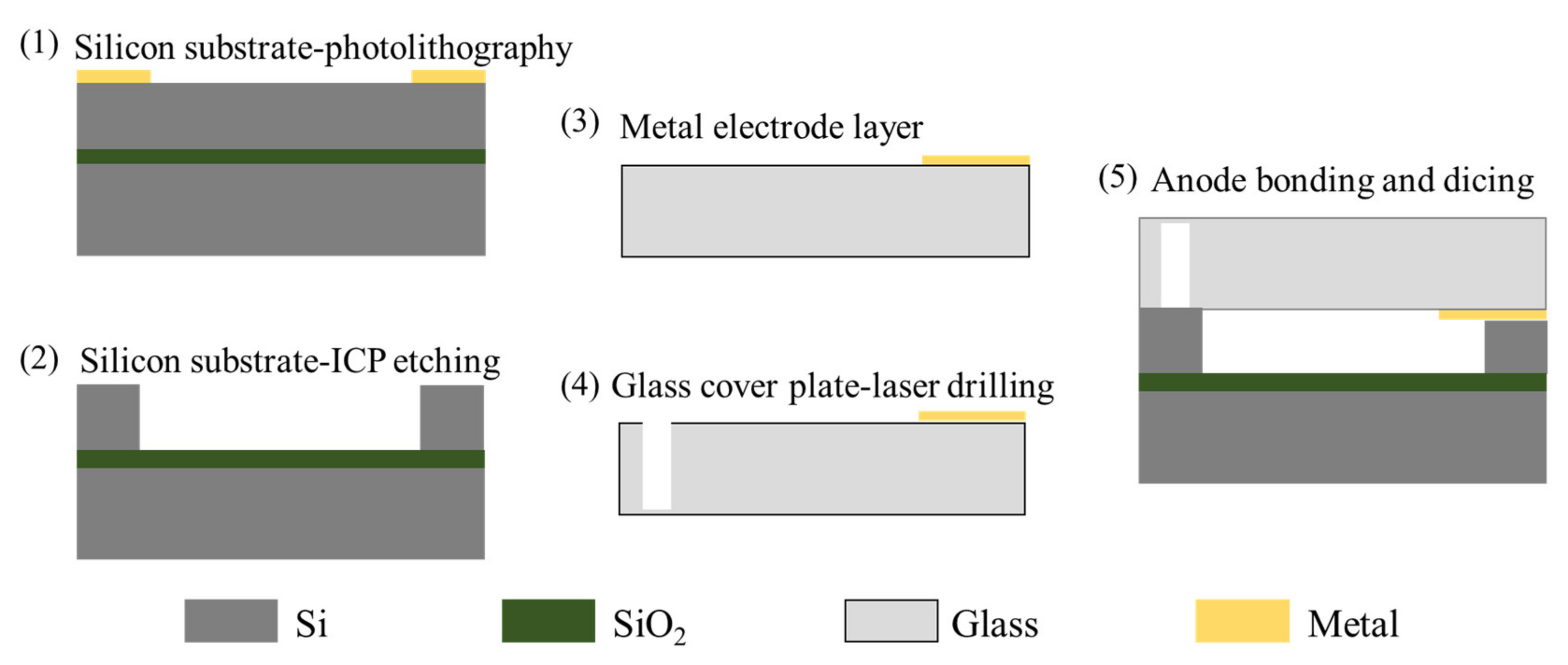 Figure 13. The special fabrication method for a liquid inertial switch.
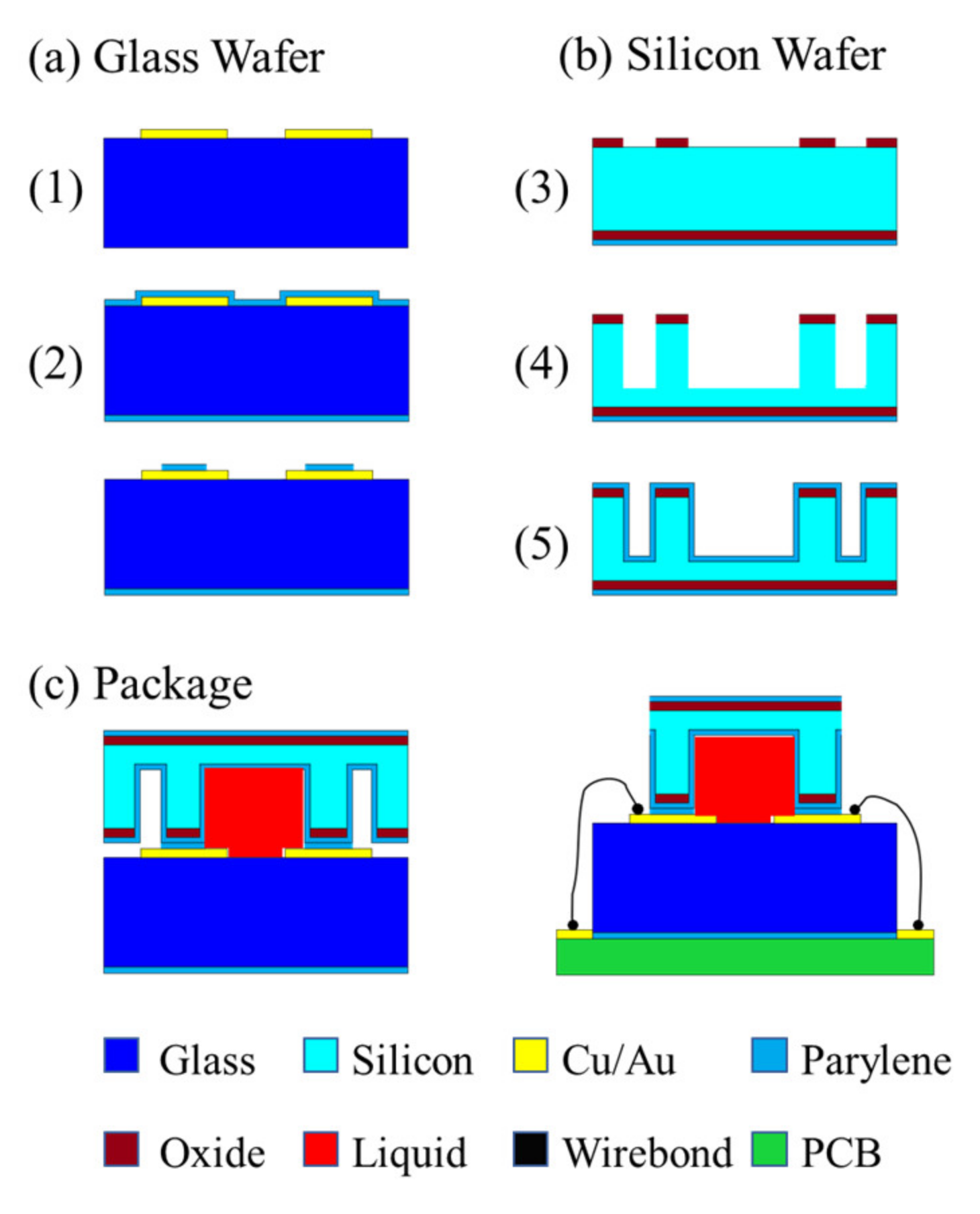 Figure 14. Manufacturing and packaging process for a fluid switch.
MEMS manufacturing process technology is the basis for supporting the development of mechanically robust, high-performance inertial switch designs. It is combined with the hermetic silicon process, which is the key to realizing a truly reliable long-life MEMS switch. An airtight protective casing is formed around the MEMS inertial switch device. Regardless of the external packaging technology used, this airtight enclosure can improve the environmental robustness and service life of the inertial switch.
5. Challenges and Prospects
In engineering practice, it is always difficult to break through bottlenecks such as inertial switch manufacturability, threshold repeatability, and threshold inconsistency. Both the bottlenecks and the opportunities for MEMS inertial switches are in progress. In order to successfully commercialize MEMS inertial switches, there are some challenges that remain and prospective trends that are worthy of attention.
(1) Persistent switches can achieve stable closure. However, they are not suitable for an engineering environment wherein repeated application is required. In addition, in early experimental tests, its one-time use feature will cause a great waste of devices, so it is necessary to study the self-unlocking method for this type of switch.
(2) DRIE and Bosch technology are able to achieve large mass preparation, and multi-layer electroforming technology makes complicated inertial switches possible with multiple direction and threshold sensitivities. However, the inherent fabrication errors and the residual stress lead to low threshold accuracy. Thence, the method of error compensation can significantly improve the threshold accuracy and sensitivity.
(3) Mature SOI technology can effectively guarantee the fabrication accuracy of the inertial switch. However, the packaging process of the inertial switch in the later stage affects the final size and application of the switch. Usually, the package shell of the inertial switch needs to have high sealing and pressure resistance to ensure air film damping, and the packaged chip is also easier to install and transport. However, most of the current switch research is limited to experimental test packaging, which is far from the packaging requirements of the actual application environment. Therefore, it is of great significance to select appropriate materials and packaging processes to bring the switch from research and development to practical applications.
(4) The surface micromachining process is compatible with the integrated circuit production process, and the integration is high. Furthermore, integrating and applying the inertial switches with integrated circuits for systematic integration is a significant trend as well.
well.
References
- Cai, H.; Ding, G.; Yang, Z.; Su, Z.; Zhou, J.; Wang, H. Design, simulation and fabrication of a novel contact-enhanced MEMS inertial switch with a movable contact point. J. Micromech. Microeng. 2008, 18, 115033.
- Chen, W.; Wang, Y.; Ding, G.; Wang, H.; Zhao, X.; Yang, Z. Simulation, fabrication and characterization of an all-metal contact-enhanced triaxial inertial microswitch with low axial disturbance. Sens. Actuators A Phys. 2014, 220, 194–203.
- Chen, W.; Yang, Z.; Wang, Y.; Ding, G.; Wang, H.; Zhao, X. Influence of applied acceleration loads on contact time and threshold in an inertial microswitch with flexible contact-enhanced structure. Sens. Actuators A Phys. 2014, 216, 7–18.
- Currano, L.J.; Becker, C.R.; Lunking, D.; Smith, G.L.; Isaacson, B.; Thomas, L. Triaxial inertial switch with multiple thresholds and resistive ladder readout. Sens. Actuators A Phys. 2013, 195, 191–197.
- Wang, Y.; Chen, W.; Yang, Z.; Ding, G.; Wang, H.; Zhao, X. An inertial micro-switch with compliant cantilever fixed electrode for prolonging contact time. In Proceedings of the 2013 IEEE 26th International Conference on Micro Electro Mechanical Systems (MEMS), Taipei, Taiwan, 20–24 January 2013; pp. 600–603.
- Xu, Q.; Yang, Z.; Fu, B.; Li, J.; Wu, H.; Zhang, Q.; Sun, Y.; Ding, G.; Zhao, X. A surface-micromachining-based inertial micro-switch with compliant cantilever beam as movable electrode for enduring high shock and prolonging contact time. Appl. Surf. Sci. 2016, 387, 569–580.
- Wang, Y.; Feng, Q.; Wang, Y.; Chen, W.; Wang, Z.; Ding, G.; Zhao, X. The design, simulation and fabrication of a novel horizontal sensitive inertial micro-switch with lowgvalue based on MEMS micromachining technology. J. Micromech. Microeng. 2013, 23, 105013.
- Whitley, M.R.; Kranz, M.; Kesmodel, R.; Burgett, S.J. Latching shock sensors for health monitoring and quality control. In MEMS/MOEMS Components and Their Applications II; International Society for Optics and Photonics: San Jose, CA, USA, 2005; pp. 185–194.
- Ongkodjojo, A.; Tay, F.E.H. Optimized design of a micromachined G-switch based on contactless configuration for health care applications. J. Phys. Conf. Ser. 2006, 34, 1044–1052.
- Xu, Q.; Yang, Z.; Sun, Y.; Lai, L.; Jin, Z.; Ding, G.; Zhao, X.; Yao, J.; Wang, J. Shock-Resistibility of MEMS-Based Inertial Microswitch under Reverse Directional Ultra-High g Acceleration for IoT Applications. Sci. Rep. 2017, 7, 45512.
- Gerson, Y.; Schreiber, D.; Grau, H.; Krylov, S. Meso scale MEMS inertial switch fabricated using an electroplated metal-on-insulator process. J. Micromech. Microeng. 2014, 24, 025008.
- Kim, H.; Jang, Y.H.; Kim, Y.K.; Kim, J.M. MEMS acceleration switch with bi-directionally tunable threshold. Sens. Actuators A Phys. 2014, 208, 120–129.
- Campanella, H.; Plaza, J.A.; Montserrat, J.; Uranga, A.; Esteve, J. High-frequency sensor technologies for inertial force detection based on thin-film bulk acoustic wave resonators (FBAR). Microelectron. Eng. 2009, 86, 1254–1257.
- Riaz, K.; Iqbal, A.; Mian, M.U.; Bazaz, S.A. Active gap reduction in comb drive of three axes capacitive micro accelerometer for enhancing sense capacitance and sensitivity. Microsyst. Technol. 2014, 21, 1301–1312.
- Wung, T.S.; Ning, Y.T.; Chang, K.H.; Tang, S.; Tsai, Y.X. Vertical-plate-type microaccelerometer with high linearity and low cross-axis sensitivity. Sens. Actuators A Phys. 2015, 222, 284–292.
- Raeisifard, H.; Bahrami, M.N.; Yousefi-Koma, A. Mechanical characterization and nonlinear analysis of a piezoelectric laminated micro-switch under electrostatic actuation. Proc. Inst. Mech. Eng. Part L J. Mater. Des. Appl. 2013, 229, 299–308.
- Bahrami, M.N.; Yousefi-Koma, A.; Raeisifard, H. Modeling and nonlinear analysis of a micro-switch under electrostatic and piezoelectric excitations with curvature and piezoelectric nonlinearities. J. Mech. Sci. Technol. 2014, 28, 263–272.
- Raeisifard, H.; Nikkhah Bahrami, M.; Yousefi-Koma, A.; Raeisi Fard, H. Static characterization and pull-in voltage of a micro-switch under both electrostatic and piezoelectric excitations. Eur. J. Mech.-A/Solids 2014, 44, 116–124.
- Zhanwen, X.; Ping, Z.; Weirong, N.; Liqun, D.; Yun, C. A novel MEMS omnidirectional inertial switch with flexible electrodes. Sens. Actuators A Phys. 2014, 212, 93–101.
- Jia, M.; Li, X.; Song, Z.; Bao, M.; Wang, Y.; Yang, H. Micro-cantilever shocking-acceleration switches with threshold adjusting and ‘on’-state latching functions. J. Micromech. Microeng. 2007, 17, 567–575.
- Guo, Z.Y.; Yang, Z.C.; Lin, L.T.; Zhao, Q.C.; Ding, H.T.; Liu, X.S.; Chi, X.Z.; Cui, J.; Yan, G.Z. A Latching acceleration switch with multi-contacts independent to the proof-mass. In Proceedings of the 2009 IEEE 22nd International Conference on Micro Electro Mechanical Systems, Sorrento, Italy, 25–29 January 2009; pp. 813–816.
- Guo, Z.Y.; Zhao, Q.C.; Lin, L.T.; Ding, H.T.; Liu, X.S.; Cui, J.; Yang, Z.C.; Xie, H.; Yan, G.Z. An acceleration switch with a robust latching mechanism and cylindrical contacts. J. Micromech. Microeng. 2010, 20, 055006.
- Brake, M.R.; Baker, M.S.; Moore, N.W.; Crowson, D.A.; Mitchell, J.A.; Houston, J.E. Modeling and Measurement of a Bistable Beam in a Microelectromechanical System. J. Microelectromech. Syst. 2010, 19, 1503–1514.
- Frangi, A.; De Masi, B.; Confalonieri, F.; Zerbini, S. Threshold Shock Sensor Based on a Bistable Mechanism: Design, Modeling, and Measurements. J. Microelectromech. Syst. 2015, 24, 2019–2026.
- Tsay, J.; Su, L.Q.; Sung, C.K. Design of a linear micro-feeding system featuring bistable mechanisms. J. Micromech. Microeng. 2005, 15, 63–70.
- Zhao, J.; Yang, Y.; Wang, H.; Jia, J. A Novel Magnetic Actuated Bistable Acceleration Switch with Low Contact Resistance. IEEE Sens. J. 2010, 10, 869–876.
- Huang, Y.C.; Sung, W.L.; Lai, W.C.; Liu, C.Y.; Fang, W. Design and implementation of time-delay switch triggered by inertia load. In Proceedings of the 2013 IEEE 26th International Conference on Micro Electro Mechanical Systems (MEMS), Taipei, Taiwan, 20–24 January 2013; pp. 729–732.
- Kuo, J.C.; Yang, Y.J. A passive hydrogel-based inertial switch integrated with micromachined LC resonator. In Proceedings of the 2012 IEEE 25th International Conference on Micro Electro Mechanical Systems (MEMS), Paris, France, 29 January–2 February 2012; pp. 515–518.
- Nie, W.; Liu, G.; Zhang, R. Microfluidic inertial switch with delay response characteristics. J. Phys. Conf. Ser. 2020, 1507, 102001.
- Shen, T.; Zhang, D.; Huang, L.; Wang, J. An automatic-recovery inertial switch based on a gallium-indium metal droplet. J. Micromech. Microeng. 2016, 26, 115016.
- Liu, T.; Su, W.; Yang, T.; Xu, Y. Vibration interference analysis and verification of micro-fluidic inertial switch. AIP Adv. 2014, 4, 031313.
- Yang, Z.; Ding, G.; Cai, H.; Zhao, X. A MEMS Inertia Switch with Bridge-Type Elastic Fixed Electrode for Long Duration Contact. IEEE Trans. Electron Devices 2008, 55, 2492–2497.
- Yang, Z.; Ding, G.; Cai, H.; Wang, H.; Chen, W.; Zhao, X. Development of a shock acceleration microswitch with enhanced-contact and low off-axis sensitivity. In Proceedings of the TRANSDUCERS 2009–2009 International Solid-State Sensors, Actuators and Microsystems Conference, Denver, CO, USA, 21–25 June 2009; pp. 1940–1943.
- Cai, H.; Yang, Z.; Ding, G.; Wang, H. Development of a Novel MEMS Inertial Switch with a Compliant Stationary Electrode. IEEE Sens. J. 2009, 9, 801–808.
- Zhang, Q.; Yang, Z.; Xu, Q.; Wang, Y.; Ding, G.; Zhao, X. Design and fabrication of a laterally-driven inertial micro-switch with multi-directional constraint structures for lowering off-axis sensitivity. J. Micromech. Microeng. 2016, 26, 055008.
- Yang, Z.; Shi, J.; Yao, J.; Zhang, X.; Ding, G.; Zhao, X. A Laterally Driven MEMS Inertial Switch with Double-Layer Suspended Springs for Improving Single-Axis Sensitivity. IEEE Trans. Compon. Packag. Manuf. Technol. 2018, 8, 1845–1854.
- Fathalilou, M.; Soltani, K.; Rezazadeh, G.; Cigeroglu, E. Enhancement of the reliability of MEMS shock sensors by adopting a dual-mass model. Measurement 2020, 153, 107428.
- Ren, C.; Wang, K.; Zhang, P.; Li, Y.; Zhao, Z.; Shi, X.; Zhang, H.; Tao, K.; Yang, Z. A Self-Powered MEMS Inertial Switch for Potential Zero Power-Consumption Wake-Up Application. J. Microelectromech. Syst. 2021, 30, 550–559.
- Raghunathan, N.; Tsutsui, W.; Chen, W.; Peroulis, D. A single crystal silicon low-g switch tolerant to impact accelerations up to 24,000 g. In Proceedings of the 2015 Transducers—2015 18th International Conference on Solid-State Sensors, Actuators and Microsystems (TRANSDUCERS), Anchorage, AK, USA, 21–25 June 2015; pp. 1144–1147.
- Kansal, P.; Kasturi, P.; Kim, N.H.; Jang, S.G. Sensitivity-Based Reliability Analysis of MEMS Acceleration Switch. Mod. Appl. Sci. 2017, 11, 123–136.
- Yang, Z.; Cai, H.; Ding, G.; Wang, H.; Zhao, X. Dynamic simulation of a contact-enhanced MEMS inertial switch in Simulink®. Microsyst. Technol. 2011, 17, 1329–1342.
- Chen, W.; Wang, Y.; Wang, Y.; Zhu, B.; Ding, G.; Wang, H.; Zhao, X.; Yang, Z. A laterally-driven micromachined inertial switch with a compliant cantilever beam as the stationary electrode for prolonging contact time. J. Micromech. Microeng. 2014, 24, 065020.
- Jean, D.; Smith, G.; Kunstmann, J. MEMS Multi-Directional Shock Sensor with Multiple Masses. U.S. Patent 7194889, 27 March 2007.
- Rödjegård, H.; Andersson, G.I.; Rusu, C.; Löfgren, M.; Billger, D. Capacitive slanted-beam three-axis accelerometer: I. Modelling and design. J. Micromech. Microeng. 2005, 15, 1989–1996.
- Wang, X.H.; Chen, Z.H.; Xiao, D.B.; Wu, X.Z. Design and Analysis of a Monolithic 3-Axis Micro-Accelerometer. Key Eng. Mater. 2012, 503, 122–127.
- Bütefisch, S.; Schoft, A.; Büttgenbach, S. Three-Axes Monolithic Silicon Low-g Accelerometer. J. Microelectromech. Syst. 2000, 9, 551–556.
- Greywall, D.S. MEMS-Based Inertial Switch. U.S. Patent 7218193, 15 May 2007.
- Lin, L.; Zhao, Q.; Yang, Z.; Zhang, D.; Yan, G. Design and simulation of a 2-axis low g acceleration switch with multi-folded beams. In Proceedings of the 2014 12th IEEE International Conference on Solid-State and Integrated Circuit Technology (ICSICT), Guilin, China, 28–31 October 2014; pp. 1–3.
- Niyazi, A.; Xu, Q.; Khan, F.; Younis, M.I. Design, Modeling, and Testing of a Bidirectional Multi-Threshold MEMS Inertial Switch. Sens. Actuators A Phys. 2021, 334, 113219.
- Xu, Q.; Wang, L.; Niyazi, A.; Younis, M.I. Multi-Threshold MEMS Shock Sensor for Quantitative Acceleration Measerements. In Proceedings of the 2021 21st International Conference on Solid-State Sensors, Actuators and Microsystems (Transducers), Orlando, FL, USA, 20–24 June 2021; pp. 120–123.
- Currano, L.J.; Becker, C.R.; Smith, G.; Isaacson, B.; Morris, C.J. 3-Axis acceleration switch for traumatic brain injury early warning. In Proceedings of the 2012 IEEE 25th International Conference on Micro Electro Mechanical Systems (MEMS), Paris, France, 29 January–2 February 2012; pp. 484–487.
- Liu, S.; Hao, Y.; Wang, S.; Li, D. MEMS-based Low-g Inertial Switch. Sens. Transducers 2014, 176, 78.
- Yang, Z.; Zhu, B.; Chen, W.; Ding, G.; Wang, H.; Zhao, X. Fabrication and characterization of a multidirectional-sensitive contact-enhanced inertial microswitch with a electrophoretic flexible composite fixed electrode. J. Micromech. Microeng. 2012, 22, 045006.
- Du, L.; Li, Y.; Zhao, J.; Wang, W.; Zhao, W.; Zhao, W.; Zhu, H. A low-g MEMS inertial switch with a novel radial electrode for uniform omnidirectional sensitivity. Sens. Actuators A Phys. 2018, 270, 214–222.
- Du, L.; Yu, Y.; Yuan, B.; Guo, B.; Wang, C.; Du, C.; Liu, J. A low-g omnidirectional MEMS inertial switch with load direction identification. Microelectron. Eng. 2021, 111679.
- Chen, W.; Wang, R.; Wang, H.; Sun, S. The Design, Simulation and Fabrication of an Omnidirectional Inertial Switch with Rectangular Suspension Spring. Micromachines 2021, 12, 440.
- Chen, W.; Wang, Y.; Zhang, Y.; Cheng, P.; Wang, Y.; Ding, G.; Zhao, X.; Yang, Z. Fabrication of a novel contact-enhanced horizontal sensitive inertial micro-switch with electroplating nickel. Microelectron. Eng. 2014, 127, 21–27.
- Xiong, Z.; Zhang, F.; Pu, Y.; Tang, B.; Yang, J.; Wang, C. Silicon-based, low-g microelectromechanical systems inertial switch for linear acceleration sensing application. Micro Nano Lett. 2015, 10, 347–350.
- Zhang, F.; Wang, C.; Yuan, M.; Tang, B.; Xiong, Z. Conception, fabrication and characterization of a silicon based MEMS inertial switch with a threshold value of 5 g. J. Micromech. Microeng. 2017, 27, 125001.
- Xiong, Z.; Wang, C.; Zhang, F.; Xie, J.; Shen, Z.; Tang, B. A Low-g MEMS Inertial Switch Based on Direct Contact Sensing Method. IEEE Trans. Compon. Packag. Manuf. Technol. 2019, 9, 1535–1541.
- Field, R.V.; Epp, D.S. Development and calibration of a stochastic dynamics model for the design of a MEMS inertial switch. Sens. Actuators A Phys. 2007, 134, 109–118.
- Hwang, J.; Ryu, D.; Park, C.; Jang, S.G.; Lee, C.I.; Kim, Y.K. Design and fabrication of a silicon-based MEMS acceleration switch working lower than 10 g. J. Micromech. Microeng. 2017, 27, 065009.
- Massad, J.E.; Sumall, H.; Epp, D.S.; Dyck, C.W. Modeling, Simulation, and Testing of the Mechanical Dynamics of an RF MEMS Switch. In Proceedings of the 2005 International Conference on MEMS, NANO and Smart Systems, Banff, AB, Canada, 24–27 July 2005; pp. 237–240.
- Nie, W.-R.; Xi, Z.-W.; Xue, W.-Q.; Zhou, Z.-J. Study on Inertial Response Performance of a Micro Electrical Switch for Fuze. Def. Technol. 2013, 9, 187–192.
- Singh, V.; Kumar, V.; Saini, A.; Khosla, P.K.; Mishra, S. Design and Development of the MEMS-Based High-g Acceleration Threshold Switch. J. Microelectromech. Syst. 2021, 30, 24–31.
- Singh, V.; Kumar, V.; Saini, A.; Khosla, P.K.; Mishra, S. Response analysis of MEMS based high-g acceleration threshold switch under mechanical shock. Int. J. Mech. Mater. Des. 2020, 17, 137–151.
- Xu, Q.; Sun, B.; Li, Y.; Xiang, X.; Lai, L.; Li, J.; Ding, G.; Zhao, X.; Yang, Z. Design and characterization of an inertial microswitch with synchronous follow-up flexible compliant electrodes capable of extending contact duration. Sens. Actuators A Phys. 2018, 270, 34–45.
- Xi, Z.; Kong, N.; Nie, W.; Cao, Y.; Zheng, C. High g MEMS inertial switch capable of direction detection. Sens. Actuators A Phys. 2019, 296, 7–16.
- Kim, H.S.; Kim, J.M.; Kim, Y.K.; Jang, Y.H. MEMS acceleration switch capable of increasing threshold acceleration. Electron. Lett. 2012, 48, 1614–1616.
- Kumar, V.; Jafari, R.; Pourkamali, S. Ultra-Low Power Digitally Operated Tunable MEMS Accelerometer. IEEE Sens. J. 2016, 16, 8715–8721.
- Ma, C.W.; Huang, P.C.; Kuo, J.C.; Kuo, W.C.; Yang, Y.J. A novel inertial switch with an adjustable acceleration threshold using an MEMS digital-to-analog converter. Microelectron. Eng. 2013, 110, 374–380.
- Abbasalipour, A.; Nikfarjam, H.; Pourkamali, S. An 8-Bit Digitally Operated Micromachined Accelerometer. J. Microelectromech. Syst. 2020, 29, 1132–1136.
- Yang, Z.; Ding, G.; Cai, H.; Xu, X.; Wang, H.; Zhao, X. Analysis and elimination of the ‘skip contact’ phenomenon in an inertial micro-switch for prolonging its contact time. J. Micromech. Microeng. 2009, 19, 045017.
- Yang, Z.; Ding, G.; Chen, W.; Fu, S.; Sun, X.; Zhao, X. Design, simulation and characterization of an inertia micro-switch fabricated by non-silicon surface micromachining. J. Micromech. Microeng. 2007, 17, 1598–1604.
- Lee, J.I.; Song, Y.; Jung, H.K.; Choi, J.; Eun, Y.; Kim, J. Carbon nanotubes-integrated inertial switch for reliable detection ofthreshold acceleration. In Proceedings of the 2011 16th International Solid-State Sensors, Actuators and Microsystems Conference, Beijing, China, 5–9 June 2011; pp. 711–714.
- Choi, J.; Lee, J.I.; Eun, Y.; Kim, M.O.; Kim, J. Aligned carbon nanotube arrays for degradation-resistant, intimate contact in micromechanical devices. Adv. Mater. 2011, 23, 2231–2236.
- Yang, Z.; Zhu, B.; Ding, G.; Wang, H.; Wang, Y.; Zhao, X. A multidirectional-sensitive inertial microswitch with electrophoretic polymer-metal composite fixed electrode for flexible contact. In Proceedings of the 2012 IEEE 25th International Conference on Micro Electro Mechanical Systems (MEMS), Paris, France, 29 January–2 February 2012; pp. 504–507.
- Wang, Y.; Yang, Z.; Xu, Q.; Chen, W.; Ding, G.; Zhao, X. Design, simulation and characterization of a MEMS inertia switch with flexible CNTs/Cu composite array layer between electrodes for prolonging contact time. J. Micromech. Microeng. 2015, 25, 085012.
- Li, J.; Wang, Y.; Li, Y.; Fu, B.; Sun, Y.; Yao, J.; Ding, G.; Zhao, X.; Yang, Z. A contact-enhanced MEMS inertial switch withelectrostatic force assistance and multi-step pulling action for prolonging contact time. Microsyst. Technol. 2018, 24, 3179–3191.
- Lee, Y.; Sim, S.M.; Kim, H.; Kim, Y.K.; Kim, J.M. Silicon MEMS acceleration switch with high reliability using hooked latch.Microelectron. Eng. 2016, 152, 10–19.
- Reddy, R.R.; Komeda, K.; Okamoto, Y.; Lebrasseur, E.; Higo, A.; Mita, Y. A zero-power sensing MEMS shock sensor with a latch-reset mechanism for multi-threshold events monitoring. Sens. Actuators A Phys. 2019, 295, 1–10.
- Ramanathan, M.; Murali, N.; Sen, P.; Pratap, R. A parametric analysis based design framework for MEMS g-switch accelerometers. Sens. Actuators A Phys. 2021, 318, 112423.
- Currano, L.J.; Bauman, S.; Churaman, W.; Peckerar, M.; Wienke, J.; Kim, S.; Yu, M.; Balachandran, B. Latching ultra-low power MEMS shock sensors for acceleration monitoring. Sens. Actuators A Phys. 2008, 147, 490–497.
- Zhang, X.; Xiang, X.; Wang, Y.; Ding, G.; Xu, X.; Yang, Z. A Heterogeneous Integrated MEMS Inertial Switch with Compliant Cantilevers Fixed Electrode and Electrostatic Locking to Realize Stable On-State. J. Microelectromech. Syst. 2019, 28, 977–986.
- Masters, N.D.; Howell, L.L. A Self-Retracting Fully-Compliant Bistable Micromechanism. J. Microelectromech. Syst. 2003,12, 273–280.
- Hansen, B.J.; Carron, C.J.; Jensen, B.D.; Hawkins, A.R.; Schultz, S.M. Plastic latching accelerometer based on bistable compliant mechanisms. Smart Mater. Struct. 2007, 16, 1967–1972.
- Eldred, M.; Subia, S.; Neckels, D.; Hopkins, M.; Notz, P.; Adams, B.; Carnes, B.; Wittwer, J.; Bichon, B.; Copps, K.D. Solution-Verified Reliability Analysis and Design of Bistable MEMS Using Error Estimation and Adaptivity; Sandia Technical Reports; SAND: Livermore, CA, USA, 2006; pp. 2006–6286.
- Zhao, J.; Liu, P.; Tang, Z.; Fan, K.; Ma, X.; Gao, R.; Bao, J. A Wireless MEMS Inertial Switch for Measuring Both Threshold Triggering Acceleration and Response Time. IEEE Trans. Instrum. Meas. 2014, 63, 3152–3161.
- Liu, M.; Zhu, Y.; Wang, C.; Chen, Y.; Wu, Y.; Zhang, H.; Du, Y.; Wang, W. A Novel Low-g MEMS Bistable Inertial Switch with Self-Locking and Reverse-Unlocking Functions. J. Microelectromech. Syst. 2020, 29, 1493–1503.
- Kim, J.; Shen, W.; Latorre, L.; Kim, C.J. A micromechanical switch with electrostatically driven liquid-metal droplet. Sens. Actuators A Phys. 2002, 97, 672–679.
- Yoo, K.; Park, U.; Kim, J. Development and characterization of a novel configurable MEMS inertial switch using a microscale liquid-metal droplet in a microstructured channel. Sens. Actuators A Phys. 2011, 166, 234–240.
- Kuo, J.C.; Kuo, P.H.; Lai, Y.T.; Ma, C.W.; Lu, S.S.; Yang, Y.J.J. A Passive Inertial Switch Using MWCNT–Hydrogel Composite with Wireless Interrogation Capability. J. Microelectromech. Syst. 2013, 22, 646–654.
- Liu, J.; Liu, Z.; Zhang, S.; Tan, Z. An Automatic-Recovery Inertial Switch Based on the Galinstan Marbles. In Proceedings of the 2021 IEEE 34th International Conference on Micro Electro Mechanical Systems (MEMS), Gainesville, FL, USA, 25–29 January 2021; pp. 818–821.
- Lin, Y.; Yang, T.; Liu, T.T.; Chen, G.Y.; Wang, C. Analysis and Simulation of Micro-Fluidic Inertial Switch. Key Eng. Mater. 2012, 503, 348–353.
- Liu, T.T.; Su, W.; Wang, C.; Yang, T. Threshold Model of Micro-Fluidic Inertial Switch Based on Orthogonal Regression Design. Key Eng. Mater. 2015, 645–646, 455–461.
- Huh, M.; Won, D.J.; Kim, J.G.; Kim, J. Simple and robust resistive dual-axis accelerometer using a liquid metal droplet. Micro Nano Syst. Lett. 2017, 5, 5.
- Won, D.J.; Huh, M.; Lee, S.; Park, U.; Yoo, D.; Kim, J. Capacitive-Type Two-Axis Accelerometer with Liquid-Type Proof Mass. Adv. Electron. Mater. 2020, 6, 1901265.