Being the earliest form of Additive manufacturing, Stereolithography (SLA) fabricates 3D objects by selectively solidifying the liquid resin through photopolymerization reaction. The ability to fabricate objects with high accuracy as well as a wide variety of materials brings much attention to stereolithography. Since its invention in 1980s, SLA underwent four generations of major technological innovation over the past 40 years. These innovations have thus result in a diversifies range of stereolithography systems with dramatically improved resolution, throughput, and materials selection for creating complex 3D objects and devices. In this paper, we review the four generations stereolithography processes, which are scanning, projection, continuous and volumetric stereolithography. For each generation, representative stereolithography system configurations are also discussed in detail. In addition, other derivative technologies, such as scanning-projection, multi-material, and magnetically assisted stereolithography processes, are also included in this review.
- Additive manufacturing, stereolithography, scannin
- Additive manufacturing
- stereolithography
- scannin
1. Development
The first significant work associated with modern stereolithography AM systems emerged during the 1970s [15][1]. Swainson[2] [16] presented a patent for a system in which 3D objects can be built by two intersecting radiation beams through either photochemically cross-linking or degrading polymers. Then, Herbert [17][3] introduced a system for building solid objects in a layer-by-layer method with photosensitive polymers. However, most people agree that modern stereolithography began with the work of CW Hull [18][4]. According to his idea (Figure 1), the 3D objects are formed layer by layer with photosensitive materials that can be cured by ultraviolet (UV) radiation. To date, stereolithography has received quite great progress and different approaches were developed for stereolithography systems. We here concluded and classified the reported approaches into four generations (Figure 2). In the early stage, the first generation stereolithography represented by Hull’s work builds 3D products by scanning a laser beam over the liquid materials. To remove the limits of low efficiency, the second generation approach, also known as projection stereolithography, is able to cure each layer simultaneously by using photo mask technology. The third generation stereolithography was arisen in 2015 by Tumbleston et al. [19][5]. They devised a process of continuous liquid interface production (CLIP), which allows a much higher print speed than that of previous approaches to produce parts in minutes instead of hours. Most recently, a volumetric stereolithography that produces 3D objects with the unit of complex aperiodic 3D volumes on a time scale of seconds was reported [20–22][6][7][8], and it can be seen as the fourth generation. However, other stereolithography systems, such as color stereolithography [23][9] and thermal stereolithography [24][10], are not reviewed in this paper.
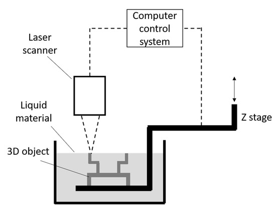
Figure 1. Hull’s stereolithography system.
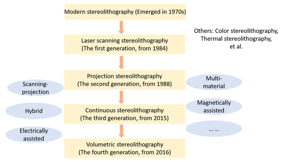
Figure 2. The overview of stereolithography [18,19,22–29][4][5][8][9][10][11][12][13][14][15]. As supplements, other kinds of processes and systems have also been provided (see Section 4), such as the scanning–projection process, hybrid stereolithography process, and multi-material process.
2. Process
The process of stereolithography (Figure 3a) starts with a standard tessellation language (STL) file, which now is the standard for every AM process [30][16]. By slicing the STL file, the 3D model is translated to 2D slices that contain the information of cross-sections [31,32][17][18]. According to these 2D slices, the physical model can be produced layer by layer. Figure 3b illustrates the structure of the STL file format. The 3D model of the STL format is represented with many small triangular facets. Each triangular facet is described by the coordinates of three vertices and a unit vector pointing outside of the facet to indicate the normal direction [33,34][19][20].
The fundament of stereolithography is the curing reaction of resins, which is an exothermic polymerization process characterized by chemical cross-linking reactions [35,36][21][22]. The reaction is initiated by supplying the energy of UV light and there are two transitions during the curing reaction process: gelation and vitrification [35,37–42][21][23][24][25][26][27][28]. Gelation is a liquid-to-rubber transition that realizes a dramatic increase in viscosity. During this transition, both gel phase and sol phase coexist in the system. Vitrification is a gradual, thermo-reversible process that leads to the transition from liquid or rubber resin to glassy solid resin [36,40,43–45][22][26][29][30][31].
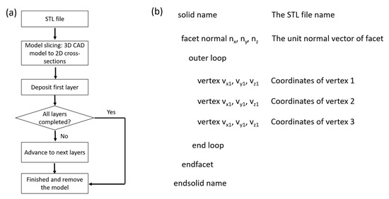
Figure 3. (a) The fabrication process of stereolithography. (b) The structure of the standard tessellation language (STL) file format.
3. Processes and Systems
Since modern stereolithography was proposed by Hull, it experienced four generations of technological innovation (Figure 2). Using different technologies, researchers have developed various kinds of physical systems for improving the performance of stereolithography. Benefiting from these systems, we are able to print sophisticated objects with several orders of magnitude in scale by using a variety of materials [9,46,47][32][33][34]. In this section, we will review the typical systems in each generation.
3.1. Laser Scanning Stereolithography
As the first generation, laser scanning stereolithography prints a 3D object by scanning a focused laser beam over the resin surface to cure the irradiated resin. To realize the scanning, some researchers used galvanometric mirrors to control the laser beam moving along the X–Y direction (Figure 4a) [48–50][35][36][37], while a motorized stage is adopted to switch the position for each layer. However, scanning with galvanometric mirrors results in defocusing of the light beam as well as optical errors [51–53][38][39][40]. Instead of galvanometric mirrors, using the X–Y translation stage with a fixed focused light beam can avoid these problems. During the printing, the focused laser point remains fixed on the resin and the X–Y translation stage is designed to move either all the optical system or the printing platform on which the object is printed. Figure 4b shows one such system, which is also known as constrained surface technique [54–58][41][42][43][44][45]. For this system, objects are produced below a transparent glass window since the fixed light beam focuses on resin through the window and the vector tracing of each layer is executed by motorized stages. The function of a transparent glass window is to push the liquid resin to avoid the fresh resin spreading on the already polymerized part of the object, which allows the layer thickness to be well controlled. However, polymerizing through a glass window causes a major drawback of the constrain-surface system, which is the adhesion of resin to the glass widow. To overcome this problem, Zissi et al.[46] [59] firstly described a scanning stereolithography system with a free surface technique in 1994 and Zhang et al.[47] [60] also introduced their free-surface system with high resolution in 1998. The typical free-surface scanning stereolithography system is illustrated in Figure 4c. Like the constrain-surface system, motorized stages are also employed in the free-surface system to trace the contour profile of each layer of objects. The fixed UV light beam focuses on the resin surface and solidifies the curable resin to produce objects above the printing platform. Without adhesion issues, the free-surface stereolithography system shows excellent capability in fabricating microstructures [61–65][48][49][50][51][52]. In addition, another important laser scanning process, two-photon polymerization (2PP), is considered as a unique photopolymerization process [28,29,66–70][14][15][53][54][55][56][57]. It differs from conventional (single-photon) stereolithography by focusing femtosecond laser pulses to a very narrow spot in which the resin is polymerized via absorbing two photons simultaneously. Therefore, two photon polymerization has advantages in fabricating micro/nano-scale structures[58] [71] with sub-100-nm resolution [72][59]. Figure 4d shows a typical setup of a 2PP system [73][60]. The most interesting part of 2PP is that it offers sub diffraction limit resolution for manufacturing fully 3D structures. Lithographic techniques with superior resolution, namely e-beam lithography, are limited to fabricate high aspect-ratio 2D structures. However, 2PP still shares the same common time-consuming issue as other scanning stereolithography methods since the fabrication of 3D structures is realized through the point-by-point addition of voxels.
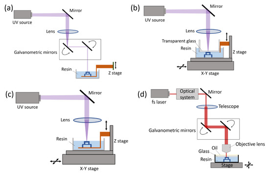
Figure 4. Scanning stereolithography processes. (a) Scanning stereolithography with dynamic light beam. (b) The constrain-surface system. (c) The free-surface system [74][61]. (d) A typical two-photon polymerization (2PP) system.
3.2. Projection Stereolithography
In contrast to the scanning process, the second generation stereolithography can print each layer of objects simultaneously with a single exposure by projecting mask patterns onto the resin surface. The original ideal of photomask was proposed by Fudim in 1980s [26,27][12][13]. Fudim developed a system that illuminates a curable resin with UV radiation through masks and a piece of flat material transparent to the radiation. Then, in the early 1990s, Pomerantz[62] [75] introduced his photomask system to produce 3D models. The working process of his system can be concluded as: deposit a thin layer resin; illuminate the resin through a xerographically created mask that has a single cross section; remove the uncured resin; fill the regions vacated by the uncured resin; cure the rest of the layer; grind the surface to build a uniform layer; repeat these steps until the object is completed. However, this kind of photomask system requires a great number of masks and precise mask alignment, which consume a lot of cost and time.
Replacing multiple mask sets with a dynamic mask is a solution to the mentioned drawbacks. Bertsch et al.[63] [76] developed a projection stereolithography system by using a liquid crystal display (LCD) as dynamic mask. Each pixel of a LCD is a small cell that can be set either to its transparent or to its opaque state by changing the orientation of the molecules it contains. Thus, LCD can be used as a dynamic mask-generator in projection stereolithography systems. The LCD-based dynamic mask was further studied in projection stereolithography by researchers[64][65][66][67][68][69][70][71] [77–84] in order to improve its performance. Although the LCD technique shows great superiority over previous processes, it has some intrinsic shortcomings. The large pixel size, very low transmission in UV and poor contrast seriously limit the further development of projection stereolithography systems.
The digital micromirror device (DMD) developed by Texas Instruments [85][72], which is widely used in video projection applications [86[73][74],87], has been adopted as a dynamic mask for projection stereolithography. The DMD is in fact an array of up to several millions of mirrors that can be controlled independently to generate mask patterns. Table 1 provides the comparison between LCD and DMD [88][75]. The first stereolithography system using DMD was reported by Bertsch et al.[76][77][78] [89–91] while a light source with visible wavelengths was used in their system. C. Sun et al.[75] [88] introduced their DMD-based stereolithography system in 2005. In their system, a UV light source and a UV curable resin of 1,6-hexanedioldiacrylate (HDDA) were used for the fabrication of complex 3D microstructures with the smallest feature of 0.6 µm. Figure 5 shows a typical top-down projection stereolithography system. Due to the high efficiency, which only depends on the layer thickness and the required exposure time, and the excellent property of DMD, projection stereolithography using DMD as a dynamic mask has been widely used for micro manufacturing applications.
Table 1. Comparison between liquid crystal display (LCD) and digital micromirror device (DMD).
|
|
LCD |
DMD |
|
UV compatibility |
No |
Yes |
|
Modulation efficiency |
12.5% (transmission) |
88% (reflection) |
|
Pitch size |
26 µm 24 µm |
14–17 µm |
|
Pixel size |
33 µm 33 µm |
13–16.2 µm |
|
Filling ratio |
57% |
91% |
|
Contrast |
100:1 |
350:1 |
|
Switching speed |
20 ms |
20 µs |
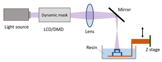
Figure 5. The top-down projection stereolithography system.
3.3. Continuous Stereolithography
Although projection stereolithography of the second generation makes it possible to cure each layer simultaneously with a single exposure, it is not a continuous manufacturing process from layer to layer. For the formation of each printed layer, three steps must be conducted sequentially: the first step is to expose resin to UV light, secondly the cured part needs to be mechanically moved either to separate from the surface of resin vat (for bottom-up systems) or to lower into the resin (for top-down systems) for resin renewal, and the third part is re-positioning [12,92,93][79][80][81]. Since each step takes several seconds, the printing speed is restricted to a few millimeters per hour. CLIP (Figure 6a) [19[5][82],94], achieved by creating a persistent liquid interface (dead zone) with an oxygen-permeable window below the UV image projection plane, is devised to print objects without stops from layer to layer. The oxygen-containing dead zone is able to inhibit the photopolymerization between the window and the polymerizing part, which allows the part to be continuously exposed while elevating. Thus, the latter two steps that existed in traditional stereolithography can be eliminated. By using the CLIP technique, the parts can be drawn out of the resin continuously at rates of hundreds of millimeters per hour. By integrating a side motion along the X axis between the resin tank and the Z platform to actively feed resin to the light exposure area, Y. Chen et al.[83][84] [95,96] also presented their continuous stereolithography system. Differing from the passive resin feeding used in the CLIP technique, the resin recoating in Y Chen’s system can be significantly accelerated by the side motion. Thus, the printing speed of continuous stereolithography is expected to be further improved. Due to strong competitive advantages, the CLIP technique has rapidly attracted a lot of attention, although it has only been a few years since it was first proposed [97,98][85][86].
In addition to CLIP, some researchers have reported their different continuous stereolithographic approaches. Chad A. Mirkin (Figure 6b) [99][87] reported a thermal controlled continuous stereolithographic approach that uses a mobile liquid interface to reduce the adhesive forces between the window and the curing objects. Since the mobile liquid interface (flowing immiscible fluorinated oil) can minimize interfacial adhesion at the build region and dissipate heat, the high-area rapid printing (HARP) can be realized by rapid print rates without thermal limitations. Timothy F. Scott et al. (Figure 6c)[88] [100] demonstrated a dual-wavelength continuous stereolithography system, where one wavelength of light is used to inhibit the polymerization while a second wavelength of light initiates polymerization of the resin. By varying the intensity of two light sources, an inhibition region can be created between the widow and the curing parts, eliminating adhesion and enabling continuous printing.
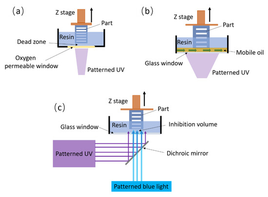
Figure 6. The continuous stereolithography processes. (a) Schematic diagram of the continuous liquid interface production (CLIP) process. (b) Schematic diagram of the high-area rapid printing (HARP) system. (c) The continuous stereolithography realized by using dual-wavelength irradiation.
3.4. Volumetrical Stereolithography
Distinguishing from previous stereolithography processes that fabricate structures layer by layer, volumetric stereolithography produces 3D objects with the formation of 3D volumes as a unit operation. Inspired by the holographic lithography, Maxim Shusteff et al.[6][8] [20,22] first introduced volumetric 3D structures patterned as a single operation into 3D printing. They designed a volumetric stereolithography system (Figure 7a) in which the superposition of patterned optical fields from three orthogonal beams were projected into a photosensitive resin. By the compensation between each beam, volumetric 3D geometries can be formed in a single exposure from the superimposed profile. Timothy F. Scott’s team further explored their dual-wavelength process to realize volumetric 3D printing (Figure 7b) [101][89]. By employing two perpendicular irradiation patterns at blue and near-UV wavelengths to independently effect either polymerization initiation or inhibition, the system allows the fabrication of objects by volumetric photopolymerization patterning in bulk resin. A promising volumetric additive manufacturing technique realized by tomographic reconstruction was separately proposed by Hayden K. Taylor et al. in 2019[7] [21] and Paul Delrot et al. in 2020 [102][90]. The tomographic volumetric stereolithography is based on the simultaneous irradiation of an entire volume of photosensitive resin. As shown in Figure 7c,d, a cylindrical container of resin is set into rotation while it is being irradiated from the side with computed patterns of light. The light patterns computed by a Radon transform, similarly to tomography [103[91][92],104], are displayed in synchronization with the rotational movement of the resin container. After the resin has been illuminated from all angles by patterns, a three-dimensional distribution of accumulated light dose is created, causing the resin to locally reach its gelation threshold, thus the desired objects can be fabricated as a whole of volume (Figure 7e,f). Currently, the volumetric additive manufacturing has shown the potential to produce complex parts with a high throughout (>105 mm3 per hour) and a wide range of materials. In the foreseeable future, volumetric stereolithography is expected to be further developed in many aspects, such as resolution, process and physical system, and combined with various fields.
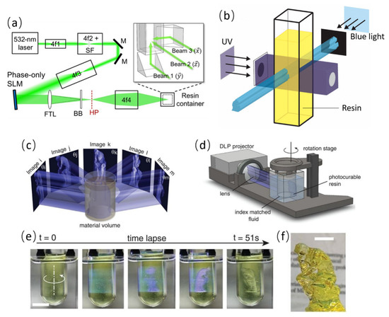
Figure 7. Volumetric stereolithography. (a) SLM, liquid crystal on silicon spatial light modulator; FTL, Fourier transform lens; BB, beam block to eliminate undiffracted light; HP, hologram plane; 4fN, telescope lens pairs in the “4-f” configuration used for beam expansion or image relaying; 4f2 incorporates a pinhole spatial filter (SF). The inset image details the configuration of 45° prism mirrors for directing image subcomponent beams at orthogonal directions into the resin volume [20][6]. (b) Schematic diagram of dual-wavelength volumetric polymerization. The polymerization process is inhibited by UV light and initiated by blue light [101][89]. (c) The concept of tomographic volumetric stereolithography: Patterned illumination from many directions delivers a computed 3D exposure dose to a photoresponsive material. (d) The tomographic volumetric stereolithography system. (e,f) show the printing process and a model printed by tomographic volumetric stereolithography. Scar bar: 10 mm [21][7].
3.5. Comparison
As stereolithography underwent four generations of major technological innovation, it provides flexible technique options for various applications. Table 2 compares four generations of stereolithography processes. By scanning a focused laser beam to cure the irradiated resin, scanning stereolithography has a large building area, which enables the capability to print large models [105][93]. Without the scanning process, projection stereolithography reduces or avoids the error caused by scanning motion and it is able to fabricate kinds of components with high accuracy [106,107][94][95]. Continuous stereolithography, which is developed based on projection stereolithography, significantly improves the yield efficiency by creating a deadzone where photopolymerization is inhibited between the window and the polymerizing part. The high output speed as well as high resolution benefit stereolithography technology by allowing precision parts to be printed in minutes . Since volumetric stereolithography builds geometries by 3D volumes, it has a high throughput and allows the processing of high viscous resins. The resolution of volumetric stereolithography is currently limited to the range of 80 to 300 um [102][90]. It is expected that the volumetric stereolithography process will further improve the resolution and explore more applications in next few years.
Table 2. Comparison of four generations of stereolithography processes.
|
Stereolithography |
Printing Speed |
System Resolution |
Printable Size |
Light Source |
|
Scanning |
Scanning speed: hundreds to thousands of millimeters per second |
A few microns (~100 nm for 2PP system) |
From tens to hundreds of millimeters |
UV light (Fs laser source for 2PP) |
|
Projection |
Tens of millimeters per hour |
A few microns (typically greater than 5 microns) |
Tens of millimeters |
UV/Visible light |
|
Continuous |
Hundreds of millimeters per hour |
A few microns (typically greater than 5 microns) |
Tens of millimeters |
UV/Visible light |
|
Volumetric |
Greater than 105 mm3 per hour |
80 ~ 300 microns |
Tens of millimeters |
UV light |
- Extensions
4. Extensions
During the development of stereolithography processes from the first to the fourth generation, researchers also presented other different processes and systems. By combining the scanning process with projection, the scanning-projection stereolithography (Fig.8a) achieves a large printing area with a high resolution [111, 112][96][97]. For example, Xiaoyu Zheng et al. [47][34] successfully fabricated 3D structures with disparate features spanning several orders of magnitude, from tens of nanometers to tens of centimeters, by scanning-projection stereolithography. To explore the advanced functional components, researchers employed stereolithography process to build 3D objects with multiple materials [113-117][98][99][100][101][102]. By changing materials during the printing, the multi-material stereolithography is able to integrate multiple (usually two or three) materials into a 3D structure. Taking advantages of certain technologies, kinds of innovative stereolithography systems are developed. Using magnetic field to constrain magnetic particles, smart components with complicated and heterogeneous functions can be effectively produced by magnetically assisted stereolithography system [118-120][103][104][105]. Similarly, by integrating with the electrical field and acoustical field respectively, the electrically assisted[106][107] [121, 122] and acoustically assisted[108] [123] stereolithography systems were reported. Fig.8b~e show an electrically assisted stereolithography system and a printed object. To expand the manufacturing capacity, researchers integrated stereolithography with other AM technologies for specific applications. As an example, a hybrid AM system was developed by integrating stereolithography with direct-write technology to fabricate 3D structures with embedded electronic circuits [124][109]. Also, the freeform stereolithography usually achieved by using robotic devices that aims to produce complex structures without additional auxiliary structures was presented [125][110].
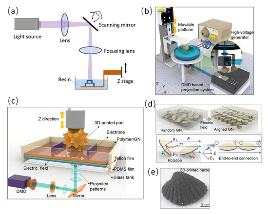
Fig.8 (a) The typical scanning-projection stereolithography system. (b) The setup of electrically assisted stereolithography system. (c) Illustration of the bottom-up projection stereolithography with electrical field. (d) The alignment of graphene nanoplatelets under the electric field and alignment mechanisms. (e) Electrically assisted 3D-printed nacre with graphene nanoplatelets [121][106].
- Conclusions
5. Conclusions
Stereolithography is an additive manufacturing technique that fabricates 3D objects by selectively solidifying the resin through photopolymerization initiated by absorbing light energy. During the decades of development, kinds of processes as well as systems of stereolithography are demonstrated, where this paper firstly categorize stereolithography processes or systems into four generations in chronological order. From scanning to projection, stereolithography is able to build 3D objects by curing each layer simultaneously instead of tracking the contour profile of each layer. While the introduction of DMD brings high resolution and production rate to stereolithography. The continuous stereolithography further improves the print speed by removing the adhesion between curing parts and the window. Volumetric stereolithography presents a new idea in building objects that allows the formation of complex aperiodic 3D volumes as an unit operation. In addition, we also briefly included some other stereolithography systems in this review. Since these progresses, stereolithography has already been widely applied to various fields. However, the pursuit of high resolution, high print speed and available size will be a meaningful topic for a long time in the future. Material is one of the major constraints for the development of stereolithography. It is necessary to develop stereolithography processes or systems for specific materials with desired properties. Also, multi-material stereolithography still needs to be further studied on the physical system, available materials and the printing process. The freeform stereolithography, on which currently few studies have been made, allows to fabricate objects with high flexibility and is expected to build complex 3D structures with additional assistance. It is expectable that the freeform stereolithography will get more attention and have a great progress.
References
[1] T.J. Wallin, J. Pikul, R.F. Shepherd, 3D printing of soft robotic systems, Nature Reviews Materials, 3 (2018) 84-100.
[2] J.J. Martin, B.E. Fiore, R.M. Erb, Designing bioinspired composite reinforcement architectures via 3D magnetic printing, Nat Commun, 6 (2015) 8641.
[3] K. Sun, T.-S. Wei, B.Y. Ahn, J.Y. Seo, S.J. Dillon, J.A. Lewis, 3D Printing of Interdigitated Li-Ion Microbattery Architectures, Advanced Materials, 25 (2013) 4539-4543.
[4] F. Zhang, M. Wei, V.V. Viswanathan, B. Swart, Y. Shao, G. Wu, C. Zhou, 3D printing technologies for electrochemical energy storage, Nano Energy, 40 (2017) 418-431.
[5] L. Ge, L. Dong, D. Wang, Q. Ge, G. Gu, A digital light processing 3D printer for fast and high-precision fabrication of soft pneumatic actuators, Sensors and Actuators A: Physical, 273 (2018) 285-292.
[6] M. Schaffner, J.A. Faber, L. Pianegonda, P.A. Ruhs, F. Coulter, A.R. Studart, 3D printing of robotic soft actuators with programmable bioinspired architectures, Nat Commun, 9 (2018) 878.
[7] D. Xue, Y. Wang, J. Zhang, D. Mei, Y. Wang, S. Chen, Projection-Based 3D Printing of Cell Patterning Scaffolds with Multiscale Channels, ACS Appl Mater Interfaces, 10 (2018) 19428-19435.
[8] Y. Ni, R. Ji, K. Long, T. Bu, K. Chen, S. Zhuang, A review of 3D-printed sensors, Applied Spectroscopy Reviews, 52 (2017) 623-652.
[9] T.D. Ngo, A. Kashani, G. Imbalzano, K.T.Q. Nguyen, D. Hui, Additive manufacturing (3D printing): A review of materials, methods, applications and challenges, Composites Part B: Engineering, 143 (2018) 172-196.
[10] B.N. Peele, T.J. Wallin, H. Zhao, R.F. Shepherd, 3D printing antagonistic systems of artificial muscle using projection stereolithography, Bioinspiration & Biomimetics, 10 (2015) 055003.
[11] S.J. Leigh, C.P. Purssell, J. Bowen, D.A. Hutchins, J.A. Covington, D.R. Billson, A miniature flow sensor fabricated by micro-stereolithography employing a magnetite/acrylic nanocomposite resin, Sensors and Actuators A: Physical, 168 (2011) 66-71.
[12] F.P. Melchels, J. Feijen, D.W. Grijpma, A review on stereolithography and its applications in biomedical engineering, Biomaterials, 31 (2010) 6121-6130.
[13] Y. He, Y. Wu, J.-z. Fu, Q. Gao, J.-j. Qiu, Developments of 3D Printing Microfluidics and Applications in Chemistry and Biology: a Review, Electroanalysis, 28 (2016) 1658-1678.
[14] X. Tian, J. Jin, S. Yuan, C.K. Chua, S.B. Tor, K. Zhou, Emerging 3D-Printed Electrochemical Energy Storage Devices: A Critical Review, Advanced Energy Materials, 7 (2017) 1700127.
[15] P.J. Bartolo, J. Gaspar, Metal filled resin for stereolithography metal part, CIRP Annals, 57 (2008) 235-238.
[16] Swainson, Medium and apparatus for producing three-dimensional figure, US Patent 4041476, 1977.
[17] A.J. Herbert, Solid object generation, Journal of Applied Photographic Engineering, 8 (1982) 185-188.
[18] C. Hull, Apparatus for production of three-dimensional objects by stereolithography, Patent No. US4575330 A, 1984.
[19] J.R. Tumbleston, D. Shirvanyants, N. Ermoshkin, R. Janusziewicz, A.R. Johnson, D. Kelly, K. Chen, R. Pinschmidt, J.P. Rolland, A. Ermoshkin, E.T. Samulski, J.M. DeSimone, Continuous liquid interface production of 3D objects, Science, 347 (2015) 1349.
[20] A.E.M.B. Maxim Shusteff, Brett E. Kelly, Johannes Henriksson, Todd H. Weisgraber, Robert M. Panas, Nicholas X. Fang, Christopher M. Spadaccini, One-step volumetric additive manufacturing of complex polymer structures, SCIENCE ADVANCES, 3 (2017) eaao5496.
[21] B.E. Kelly, I. Bhattacharya, H. Heidari, M. Shusteff, C.M. Spadaccini, H.K. Taylor, Volumetric additivemanufacturing via tomographic reconstruction, Science, 363 (2019) 1075-1079.
[22] R.M.P. Maxim Shusteff, Johannes Henriksson, Brett E. Kelly, Allison E. M. Browar, Nicholas X. Fang, Christopher M. Spadaccini, Additive fabrication of 3D structures by holographic lithography, Solid Freeform Fabrication 2016: Proceedings of the 26th Annual International Solid Freeform Fabrication Symposium DOI (2016) 1183-1192.
[23] Y.G. Im, S.I. Chung, J.H. Son, Y.D. Jung, J.G. Jo, H.D. Jeong, Functional prototype development: inner visible multi-color prototype fabrication process using stereo lithography, Journal of Materials Processing Technology, 130-131 (2002) 372-377.
[24] T.A. Almquist, Thermal stereolithography, US Patent 5695707, 1997.
[25] C. Hull, Method and apparatus for production, US Patent 5137662, 1992.
[26] Fudim, Method and apparatus for production of three dimensional objects by photo, US Patent 4752498, 1988.
[27] Fudim, Method and apparatus for production of three dimensional objects by photo solidification, US Patent 4801477, 1989.
[28] E. Stratakis, A. Ranella, M. Farsari, C. Fotakis, Laser-based micro/nanoengineering for biological applications, Progress in Quantum Electronics, 33 (2009) 127-163.
[29] Y.-X. Yan, X.-T. Tao, Y.-H. Sun, G.-B. Xu, C.-K. Wang, J.-X. Yang, X. Zhao, Y.-Z. Wu, Y. Ren, M.-H. Jiang, Two new asymmetrical two-photon photopolymerization initiators: Synthesis, characterization and nonlinear optical properties, Optical Materials, 27 (2005) 1787-1792.
[30] K.V. Wong, A. Hernandez, A Review of Additive Manufacturing, ISRN Mechanical Engineering, 2012 (2012) 1-10.
[31] J. Hu, Study on STL-based slicing process for 3D printing Solid Freeform Fabrication 2017: Proceedings of the 28th Annual International Solid Freeform Fabrication Symposium DOI (2017) 885-895.
[32] A.D.a.I. Makela, Slicing procedures for layered manufacturing techniques, Computer-Aided Design, 26 (1994).
[33] M. Szilvśi-Nagy, G. Mátyási, Analysis of STL files, Mathematical and Computer Modelling, 38 (2003) 945-960.
[34] F. Bianconi, Bridging the gap between CAD and CAE using STL files, International Journal of CAD/CAM, 2 (2002) 55-67.
[35] H.B. Olayan, H.S. Hami, E.D. Owen, Photochemical and Thermal Crosslinking of Polymers, Journal of Macromolecular Science, Part C: Polymer Reviews, 36 (1996) 671-719.
[36] P.J. Bartolo, Stereolithography: materail, processes and application, Springer Science & Business Media2011.
[37] J.K. Gillham, Award address formation and properties of network polymeric materials, Polymer Engineering & Science, 19 (1979) 676-682.
[38] J.K. Gillham, Characterization of thermosetting materials by torsional braid analysis, Polymer Engineering & Science, 16 (1976) 353-356.
[39] J. Lange, N. Altmann, C.T. Kelly, P.J. Halley, Understanding vitrification during cure of epoxy resins using dynamic scanning calorimetry and rheological techniques, Polymer, 41 (2000) 5949-5955.
[40] J.C. Domínguez, M.V. Alonso, M. Oliet, F. Rodríguez, Chemorheological study of the curing kinetics of a phenolic resol resin gelled, European Polymer Journal, 46 (2010) 50-57.
[41] S. Lun̆ak, J. Vladyka, K. Dus̆ek, Effect of diffusion control in the glass transition region on critical conversion at the gel point during curing of epoxy resins, Polymer, 19 (1978) 931-933.
[42] S. Montserrat, F. Roman, P. Colomer, Vitrification and dielectric relaxation during the isothermal curing of an epoxy–amine resin, Polymer, 44 (2003) 101-114.
[43] A. Cadenato, J.M. Salla, X. Ramis, J.M. Morancho, L.M. Marroyo, J.L. Martin, Determination of gel and vitrification times of thermoset curing process by means of TMA, DMTA and DSC techniques, Journal of thermal analysis, 49 (1997) 269-279.
[44] C.-Y.M. Tung, P.J. Dynes, Relationship between viscoelastic properties and gelation in thermosetting systems, Journal of Applied Polymer Science, 27 (1982) 569-574.
[45] W.X. Zukas, Torsional braid analysis of the aromatic amine cure of epoxy resins, Journal of Applied Polymer Science, 53 (1994) 429-440.
[46] X. Wang, M. Jiang, Z. Zhou, J. Gou, D. Hui, 3D printing of polymer matrix composites: A review and prospective, Composites Part B: Engineering, 110 (2017) 442-458.
[47] X. Zheng, W. Smith, J. Jackson, B. Moran, H. Cui, D. Chen, J. Ye, N. Fang, N. Rodriguez, T. Weisgraber, C.M. Spadaccini, Multiscale metallic metamaterials, Nat Mater, 15 (2016) 1100-1106.
[48] A. Marc L. M. McAllister, CMRT, Application of stereolithography to subperiosteal implant manufacture, Journal of Oral Implantology, 24 (1998) 89-92.
[49] B. Gu, H. Helvajian, A. Piqué, C.M. Dunsky, J. Liu, X. Luo, J. Li, M. Lucas, Galvanometer scanning technology for laser additive manufacturing, International Society for Optics and Photonics, 10095 (2017) 1009512.
[50] W. Wang, J. Ye, H. Gong, X. Pi, C. Wang, Y. Xia, Computer-stereolithography-based laser rapid prototyping & manufacturing system, IFAC Proceedings Volumes, 32 (1999) 61-66.
[51] W. Li, L. Mitchell, Error analysis and improvements for using parallel-shift method to test a galvanometer-based laser scanning system, SPIE1994.
[52] K. Pelsue, Precision, Post-Objective, Two-Axis, Galvanometer Scanning, SPIE1982.
[53] J. Huang, Q. Qin, J. Wang, H. Fang, Two Dimensional Laser Galvanometer Scanning Technology for Additive Manufacturing, International Journal of Materials, Mechanics and Manufacturing, 6 (2018) 332-336.
[54] T. Takagi, N. Nakajima, Photoforming applied to fine machining, [1993] Proceedings IEEE Micro Electro Mechanical Systems, 1993, pp. 173-178.
[55] K. Ikuta, K. Hirowatari, Real three dimensional micro fabrication using stereo lithography and metal molding, [1993] Proceedings IEEE Micro Electro Mechanical Systems, 1993, pp. 42-47.
[56] T. Takagi, N. Nakajima, Architecture combination by micro photoforming process, Proceedings IEEE Micro Electro Mechanical Systems An Investigation of Micro Structures, Sensors, Actuators, Machines and Robotic Systems, 1994, pp. 211-216.
[57] T. Takagi, N. Nakajima, Photoforming Applied to Fine Forming, JSME international journal. Ser. C, Dynamics, control, robotics, design and manufacturing, 38 (1995) 811-817.
[58] K. Ikuta, K. Hirowatari, T. Ogata, Three dimensional micro integrated fluid systems (MIFS) fabricated by stereo lithography, Proceedings IEEE Micro Electro Mechanical Systems An Investigation of Micro Structures, Sensors, Actuators, Machines and Robotic Systems, 1994, pp. 1-6.
[59] S. Zissi, A. Bertsch, S. Ballandras, S. Corbel, J. Jézéquel, С. Belin, D. Lougnot, J. André, Limites de la stéréolithographie pour des applications microtechniques, Proceedings of the 3e Assises Européennes du Prototypage Rapide, 1994, pp. 19.
[60] X. Zhang, X. Jiang, C. Sun, Micro-stereolithography for MEMS, Proceedings of the 1998 ASME International Mechanical Engineering Congress and Exposition, ASME, 1998, pp. 3-9.
[61] X.N.J. X. Zhang, C. Sun, Micro-stereolithography of polymeric and ceramic microstructures, Sensors and Actuators A: Physical, 77 (1999) 149-156.
[62] C.S. X.N. Jiang, X. Zhang, B.Xu, Y.H. Ye Microstereolithography of lead zirconate titanate thick film on silicon substrate, Sensors and Actuators A: Physical, 87 (2000) 72-77.
[63] J.P.F. Malcolm N. Cooke, David Dean, Clare Rimnac, Antonios G. Mikos, Use of stereolithography to manufacture critical‐sized 3D biodegradable scaffolds for bone ingrowth, Journal of Biomedical Materials Research Part B: Applied Biomaterials, 64 (2002) 65-69.
[64] S.W. Kee-Won Lee, Bradley C. Fox, Erik L. Ritman, Michael J. Yaszemski and Lichun Lu, Poly (propylene fumarate) bone tissue engineering scaffold fabrication using stereolithography: effects of resin formulations and laser parameters, Biomacromolecules, 8 (2007) 1077-1084.
[65] J.W. Lee, P.X. Lan, B. Kim, G. Lim, D.-W. Cho, 3D scaffold fabrication with PPF/DEF using micro-stereolithography, Microelectronic Engineering, 84 (2007) 1702-1705.
[66] K.J. Schafer, J.M. Hales, M. Balu, K.D. Belfield, E.W. Van Stryland, D.J. Hagan, Two-photon absorption cross-sections of common photoinitiators, Journal of Photochemistry and Photobiology A: Chemistry, 162 (2004) 497-502.
[67] S. Kawata, H.-B. Sun, Two-photon photopolymerization as a tool for making micro-devices, Applied Surface Science, 208-209 (2003) 153-158.
[68] M. Miwa, S. Juodkazis, T. Kawakami, S. Matsuo, H. Misawa, Femtosecond two-photon stereo-lithography, Applied Physics A, 73 (2001) 561-566.
[69] K.-S. Lee, D.-Y. Yang, S.H. Park, R.H. Kim, Recent developments in the use of two-photon polymerization in precise 2D and 3D microfabrications, Polymers for Advanced Technologies, 17 (2006) 72-82.
[70] S. Wu, J. Serbin, M. Gu, Two-photon polymerisation for three-dimensional micro-fabrication, Journal of Photochemistry and Photobiology A: Chemistry, 181 (2006) 1-11.
[71] S.H. Park, D.Y. Yang, K.S.J.L. Lee, P. Reviews, Two‐photon stereolithography for realizing ultraprecise three‐dimensional nano/microdevices, 3 (2009) 1-11.
[72] M. Farsari, B.N. Chichkov, Two-photon fabrication, Nature Photonics, 3 (2009) 450-452.
[73] A.O. Jesper Serbin, and Boris Chichkov, Fabrication of woodpile structures by two-photon polymerization and investigation of their optical properties, OPTICS EXPRESS, 12 (2004) 5221-5228.
[74] K.S. Lee, D.Y. Yang, S.H. Park, R.H.J.P.f.a.t. Kim, Recent developments in the use of two‐photon polymerization in precise 2D and 3D microfabrications, Polymers advanced technologies, 17 (2006) 72-82.
[75] K.I. Kengo KOBAYASHI, Development of free-surface microstereolithography with ultra-high resolution to fabricate hybrid 3-D microdevices, IEEE International symposium on Micro-Nano Mechatronics and Human Schience, DOI (2005).
[76] I. Pomerantz, Three dimensional modeling apparatus, US Patent 4961154, 1990.
[77] S.Z. A. Bertsch, J.Y. Je´´ ze´´ quel, S. Corbel, J.C. Andre´´, Microstereophotolithography using a liquid crystal display as dynamic mask-generator, Microsystem Technologies, 3 (1997) 42-47.
[78] T. Nakamoto, K. Yamaguchi, P.A. A, Consideration on the producing of high aspect ratio micro parts using UV sensitive photopolymer, MHS'96 Proceedings of the Seventh International Symposium on Micro Machine and Human Science, 1996, pp. 53-58.
[79] V. Loubère, S. Monneret, S. Corbel, Microstereolithography using a mask-generator display, Proc. of the 4th Japan-France Congress and 2nd Asia-Europe Congress on Mechatronics, 1998, pp. 160-163.
[80] M. Serge, L. Virginie, C. Serge, Microstereolithography using a dynamic mask generator and a noncoherent visible light source, Proc.SPIE, 1999.
[81] C. Chatwin, M. Farsari, S. Huang, M. Heywood, P. Birch, R. Young, J.J.A.o. Richardson, UV microstereolithography system that uses spatial light modulator technology, 37 (1998) 7514-7522.
[82] M. Farsari, F. Claret-Tournier, S. Huang, C.R. Chatwin, D.M. Budgett, P.M. Birch, R.C.D. Young, J.D. Richardson, A novel high-accuracy microstereolithography method employing an adaptive electro-optic mask, Journal of Materials Processing Technology, 107 (2000) 167-172.
[83] M. Farsari, S. Huang, P. Birch, F. Claret-Tournier, R. Young, D. Budgett, C. Bradfield, C. Chatwin, Microfabrication by use of a spatial light modulator in the ultraviolet:?experimental results, Opt. Lett., 24 (1999) 549-550.
[84] H. Nishino, T. Miyoshi, Y. Takaya, S. Takahashi, T. Hayashi, K. Kimura, S.K. Kaishi, Study on nonlaminate micro stereolithography using LCD mask (2nd report)-Thin layer laminating fabrication using LCD live-motion Mask, Journal of the Japan Society for Precision Engineering, 69 (2003) 1417-1422.
[85] H. Imahori, T. Miyoshi, Y. Takaya, T. Hayashi, Micro-Stereolithography of Dot Shapes for Lightguide Using LCD Grayscale Mask, The Japan Society of Precision Eng., Autumn Meeting, Citeseer, 2005.
[86] S. Monneret, B. Courtois, V. Loubere, S.B. Crary, W. Ehrfeld, S. Corbel, H. Fujita, J.M. Karam, K.W. Markus, Microstereolithography using a dynamic mask generator and a noncoherent visible light source, Design, Test, and Microfabrication of MEMS and MOEMS, 1999.
[87] M.Y. Jack, Projection display systems based on the Digital Micromirror Device (DMD), Proc.SPIE, 1995.
[88] L. Hornbeck, Digital Light Processing (TM) for high-brightness high-resolution applications Projection Displays III, SPIE, San Jose CA, 1997.
[89] W.E. Nelson, R.L. Bhuva, Digital micromirror device imaging bar for hard copy, Color Hard Copy and Graphic Arts IV, International Society for Optics and Photonics, 1995, pp. 58-65.
[90] C. Sun, N. Fang, D.M. Wu, X. Zhang, Projection micro-stereolithography using digital micro-mirror dynamic mask, Sensors and Actuators A: Physical, 121 (2005) 113-120.
[91] H.L.a.P.R. A. Bertsch, Combining microstereolithography and thick resist UV lithography for 3D microfabrication, 11th IEEE Workshop on Micro Electro Mechanical Systems (MEMS’98), Heidelberg, Germany, 1998, pp. 18-23.
[92] A.B.a.P.R. Laurence Beluze, Microstereolithography: a new process to build complex 3D objects, SPIE Symposium on Design, Test and microfabrication of MEMs/MOEMs, Pairs, France, 1999, pp. 808-817.
[93] J.Y.J.z.q. A. Bertsch, J.C. Andre, Study of Spatial Resolution of a new 3D Microfabrication Process the Microstereophotolithography Using a Dynamic Mask generator Technique, Journal of Photochemistry and Photobiology A: Chemistry 107 (1997) 275-281.
[94] P.F. Jacobs, Rapid prototyping & manufacturing: fundamentals of stereolithography, Society of Manufacturing Engineers1992.
[95] B. Mueller, Additive Manufacturing Technologies – Rapid Prototyping to Direct Digital Manufacturing, Assembly Automation, 32 (2012).
[96] R. Janusziewicz, J.R. Tumbleston, A.L. Quintanilla, S.J. Mecham, J.M.J.P.o.t.N.A.o.S. DeSimone, Layerless fabrication with continuous liquid interface production, 113 (2016) 11703-11708.
[97] X. Li, H. Mao, Y. Pan, Y. Chen, Mask video projection based stereolithography with continuous resin flow to build digital models in minutes, ASME 2018 13th International Manufacturing Science and Engineering Conference, American Society of Mechanical Engineers Digital Collection, 2018.
[98] X. Li, H. Mao, Y. Pan, Y. Chen, Engineering, Mask Video Projection-Based Stereolithography With Continuous Resin Flow, Journal of Manufacturing Science, 141 (2019).
[99] G. Shao, R. Hai, C.J.A.O.M. Sun, 3D Printing Customized Optical Lens in Minutes, 8 (2020) 1901646.
[100] H.O.T. Ware, C. Sun, Method for Attaining Dimensionally Accurate Conditions for High-Resolution Three-Dimensional Printing Ceramic Composite Structures Using MicroCLIP Process, Journal of Micro Nano-Manufacturing, 7 (2019).
[101] J.L.H. David A. Walker, Chad A. Mirkin, Rapid, large-volume, thermally controlled 3D printing using a mobile liquid interface, Science, 366 (2019) 360-364.
[102] H.L.v.d.L. Martin P. de Beer, Megan A. Cole, Riley J. Whelan, Mark A. Burns, Timothy F. Scott, rapid, continuous AM by volumetric polymerization inhibition patterning, SCIENCE ADVANCES 5(2019) eaau8723.
[103] H.L. van der Laan, M.A. Burns, T.F. Scott, Volumetric Photopolymerization Confinement through Dual-Wavelength Photoinitiation and Photoinhibition, ACS Macro Letters, 8 (2019) 899-904.
[104] D. Loterie, P. Delrot, C. Moser, High-resolution tomographic volumetric additive manufacturing, Nat Commun, 11 (2020) 852.
[105] A.C. Kak, M. Slaney, G. Wang, Principles of computerized tomographic imaging, Medical Physics, 29 (2002) 107-107.
[106] B. Kelly, I. Bhattacharya, M. Shusteff, R.M. Panas, H.K. Taylor, C.M. Spadaccini, Computed Axial Lithography (CAL): Toward Single Step 3D Printing of Arbitrary Geometries, arXiv preprint arXiv:.05893, DOI (2017).
[107] L. Cheung, M. Wong, L. Wong, The applications of stereolithography in facial reconstructive surgery, Proceedings International Workshop on Medical Imaging and Augmented Reality, IEEE, 2001, pp. 10-15.
[108] X. Chen, W. Liu, B. Dong, J. Lee, H.O.T. Ware, H.F. Zhang, C. Sun, High-Speed 3D Printing of Millimeter-Size Customized Aspheric Imaging Lenses with Sub 7 nm Surface Roughness, Adv Mater, 30 (2018) e1705683.
[109] M.J. Yin, M. Yao, S. Gao, A.P. Zhang, H.Y. Tam, P.K.A.J.A.M. Wai, Rapid 3D patterning of poly (acrylic acid) ionic hydrogel for miniature pH sensors, 28 (2016) 1394-1399.
[110] G. Shao, R. Hai, C. Sun, 3D Printing Customized Optical Lens in Minutes, Advanced Optical Materials, 8 (2020) 1901646.
[111] M.M. Emami, F. Barazandeh, F. Yaghmaie, Scanning-projection based stereolithography: Method and structure, Sensors and Actuators A: Physical, 218 (2014) 116-124.
[112] M.P. Lee, G.J. Cooper, T. Hinkley, G.M. Gibson, M.J. Padgett, L. Cronin, Development of a 3D printer using scanning projection stereolithography, Sci Rep, 5 (2015) 9875.
[113] J.-W. Choi, H.-C. Kim, R. Wicker, Multi-material stereolithography, Journal of Materials Processing Technology, 211 (2011) 318-328.
[114] D. Han, C. Yang, N.X. Fang, H. Lee, Rapid multi-material 3D printing with projection micro-stereolithography using dynamic fluidic control, Additive Manufacturing, 27 (2019) 606-615.
[115] R.B. Wicker, E.W.J.V. MacDonald, Multi-material, multi-technology stereolithography: This feature article covers a decade of research into tackling one of the major challenges of the stereolithography technique, which is including multiple materials in one construct, Virtual and Physical Prototyping, 7 (2012) 181-194.
[116] C. Zhou, Y. Chen, Z. Yang, B. Khoshnevis, Development of multi-material mask-image-projection-based stereolithography for the fabrication of digital materials, Annual solid freeform fabrication symposium, Austin, TX, 2011, pp. 65-80.
[117] K. Arcaute, B. Mann, R.J.A.b. Wicker, Stereolithography of spatially controlled multi-material bioactive poly (ethylene glycol) scaffolds, 6 (2010) 1047-1054.
[118] L. Lu, P. Guo, Y. Pan, Magnetic-Field-Assisted Projection Stereolithography for Three-Dimensional Printing of Smart Structures, Journal of Manufacturing Science and Engineering, 139 (2017) 071008-071008-071007.
[119] D. Kokkinis, M. Schaffner, A.R. Studart, Multimaterial magnetically assisted 3D printing of composite materials, Nature communications, 6 (2015) 1-10.
[120] L. Lu, E. Baynojir Joyee, Y. Pan, Correlation between microscale magnetic particle distribution and magnetic-field-responsive performance of three-dimensional printed composites, Journal of Micro Nano-Manufacturing, 6 (2018).
[121] Y. Yang, X. Li, M. Chu, H. Sun, J. Jin, K. Yu, Q. Wang, Q. Zhou, Y. Chen, Electrically assisted 3D printing of nacre-inspired structures with self-sensing capability, Science advances, 5 (2019) eaau9490.
[122] Y. Yang, Z. Chen, X. Song, Z. Zhang, J. Zhang, K.K. Shung, Q. Zhou, Y. Chen, Biomimetic anisotropic reinforcement architectures by electrically assisted nanocomposite 3D printing, Advanced materials, 29 (2017) 1605750.
[123] L. Lu, X. Tang, S. Hu, Y. Pan, Acoustic Field-Assisted Particle Patterning for Smart Polymer Composite Fabrication in Stereolithography, 3D Printing and Additive Manufacturing, 5 (2018) 151-159.
[124] A. Joe Lopes, E. MacDonald, B. Wicker Ryan, Integrating stereolithography and direct print technologies for 3D structural electronics fabrication, Rapid Prototyping Journal, 18 (2012) 129-143.
[125] A.G. Stevens, C.R. Oliver, M. Kirchmeyer, J. Wu, L. Chin, E.S. Polsen, C. Archer, C. Boyle, J. Garber, A.J. Hart, Conformal Robotic Stereolithography, 3D Print Addit Manuf, 3 (2016) 226-235.
References
- Paulo Jorge Bartolo; J. Gaspar; Metal filled resin for stereolithography metal part. CIRP Annals 2008, 57, 235-238, 10.1016/j.cirp.2008.03.124.
- Swainson, W.K. Method, Medium and Apparatus for Producing Three-Dimensional Figure Product. U.S. Patent 4,041,476, 9 August 1977.
- Herbert, A.J.; Solid object generation. J. Appl. Photogr. Eng. 1982, 8, 185–188.
- Hull, C.W. Apparatus for Production of Three-Dimensional Objects by Stereolithography. U.S. Patent Appl. 638,905, 1984.
- J. R. Tumbleston; D. Shirvanyants; N. Ermoshkin; R. Janusziewicz; A. R. Johnson; D. Kelly; K. Chen; R. Pinschmidt; J. P. Rolland; E. T. Samulski; et al.J. M. DeSimoneA. Ermoshkin Continuous liquid interface production of 3D objects. Science 2015, 347, 1349-1352, 10.1126/science.aaa2397.
- Shusteff, M.; Browar, A.E.M.; Kelly, B.E.; Henriksson, J.; Weisgraber, T.H.; Panas, R.M.; Fang, N.X.; Spadaccini, C.M. One-step volumetric additive manufacturing of complex polymer structures. Sci. Adv. 2017, 3, eaao5496.
- Kelly, B.E.; Bhattacharya, I.; Heidari, H.; Shusteff, M.; Spadaccini, C.M.; Taylor, H.K. Volumetric additivemanufacturing via tomographic reconstruction. Science 2019, 363, 1075–1079.
- Shusteff, M.; Panas, R.M.; Henriksson, J.; Kelly, B.E.; Browar, A.E.M.; Fang, N.X.; Spadaccini, C.M. Additive fabrication of 3D structures by holographic lithography. In Proceedings of the 27th Annual International Solid Freeform Fabrication Symposium, Austin, TX, USA, 13–16 August 2016; pp. 8–10.
- Y.G Im; S.I Chung; J.H Son; Y.D Jung; J.G Jo; H.D Jeong; Functional prototype development: inner visible multi-color prototype fabrication process using stereo lithography. Journal of Materials Processing Technology 2002, 130-131, 372-377, 10.1016/s0924-0136(02)00826-9.
- Almquist, T.A.; Dennis, R.S. Thermal Stereolithography. U.S. Patent 5,672,312, 30 September 1997
- Hull, C. Method and Apparatus for Production. U.S. Patent 5,137,662, 11 August 1992.
- Fudim, E.V. Method and Apparatus for Production of Three Dimensional Objects by Photosolidification. U.S. Patent 4,752,498, 21 June 1988.
- Fudim, E.V. Method and Apparatus for Production of Three Dimensional Objects by Photosolidification. U.S. Patent 4,801,477, 31 January 1989.
- Stratakis, E.; Ranella, A.; Farsari, M.; Fotakis, C. Laser-based micro/nanoengineering for biological applications. Prog. Quantum Electron. 2009, 33, 127–163.
- Yan, Y.-X.; Tao, X.-T.; Sun, Y.-H.; Xu, G.-B.; Wang, C.-K.; Yang, J.-X.; Zhao, X.; Wu, Y.-Z.; Ren, Y.; Jiang, M.-H. Two new asymmetrical two-photon photopolymerization initiators: Synthesis, characterization and nonlinear optical properties. Opt. Mater. 2005, 27, 1787–1792.
- Wong, K.V.; Hernandez, A.; A Review of Additive Manufacturing. ISRN Mech. Eng. 2012, 2012, 1–10.
- Hu, J. Study on STL-based slicing process for 3D printing. In Proceedings of the 28th Annual International Solid Freeform Fabrication Symposium, Austin, TX, USA, 7–9 August 2017; pp. 885–895.
- Makela, A.D.a.I. Slicing procedures for layered manufacturing techniques. Comput. Aided Des. 1994, 26, 119–126.
- Szilvśi-Nagy, M.; Mátyási, G. Analysis of STL files. Math. Comput. Model. 2003, 38, 945–960.
- Bianconi, F. Bridging the gap between CAD and CAE using STL files. Int. J. CAD CAM 2002, 2, 55–67.
- Olayan, H.B.; Hami, H.S.; Owen, E.D. Photochemical and Thermal Crosslinking of Polymers. J. Macromol. Sci. Part C Polym. Rev. 1996, 36, 671–719.
- Bartolo, P.J. Stereolithography: Materail, Processes and Application; Springer Science & Business Media: Berlin, Germany, 2011.
- Gillham, J.K. Award address formation and properties of network polymeric materials. Polym. Eng. Sci. 1979, 19, 676–682.
- Gillham, J.K. Characterization of thermosetting materials by torsional braid analysis. Polym. Eng. Sci. 1976, 16, 353–356.
- Lange, J.; Altmann, N.; Kelly, C.T.; Halley, P.J. Understanding vitrification during cure of epoxy resins using dynamic scanning calorimetry and rheological techniques. Polymer 2000, 41, 5949–5955.
- Domínguez, J.C.; Alonso, M.V.; Oliet, M.; Rodríguez, F. Chemorheological study of the curing kinetics of a phenolic resol resin gelled. Eur. Polym. J. 2010, 46, 50–57.
- Lunak, S.; Vladyka, J.; Dusek, K. Effect of diffusion control in the glass transition region on critical conversion at the gel point during curing of epoxy resins. Polymer 1978, 19, 931–933.
- Montserrat, S.; Roman, F.; Colomer, P. Vitrification and dielectric relaxation during the isothermal curing of an epoxy–amine resin. Polymer 2003, 44, 101–114.
- Cadenato, A.; Salla, J.M.; Ramis, X.; Morancho, J.M.; Marroyo, L.M.; Martin, J.L. Determination of gel and vitrification times of thermoset curing process by means of TMA, DMTA and DSC techniques. J. Therm. Anal. 1997, 49, 269–279.
- Tung, C.-Y.M.; Dynes, P.J. Relationship between viscoelastic properties and gelation in thermosetting systems. J. Appl. Polym. Sci. 1982, 27, 569–574.
- Zukas, W.X. Torsional braid analysis of the aromatic amine cure of epoxy resins. J. Appl. Polym. Sci. 1994, 53, 429–440.
- Tuan Ngo; Alireza Kashani; Gabriele Imbalzano; Q. Nguyen; David Hui; Additive manufacturing (3D printing): A review of materials, methods, applications and challenges. Composites Part B: Engineering 2018, 143, 172-196, 10.1016/j.compositesb.2018.02.012.
- Wang, X.; Jiang, M.; Zhou, Z.; Gou, J.; Hui, D. 3D printing of polymer matrix composites: A review and prospective. Compos. Part B Eng. 2017, 110, 442–458.
- Zheng, X.; Smith, W.; Jackson, J.; Moran, B.; Cui, H.; Chen, D.; Ye, J.; Fang, N.; Rodriguez, N.; Weisgraber, T.; et al. Multiscale metallic metamaterials. Nat. Mater. 2016, 15, 1100–1106
- Marc, L.M.; McAllister, A.; CMRT. Application of stereolithography to subperiosteal implant manufacture. J. Oral Implantol. 1998, 24, 89–92.
- Gu, B.; Helvajian, H.; Piqué, A.; Dunsky, C.M.; Liu, J.; Luo, X.; Li, J.; Lucas, M. Galvanometer scanning technology for laser additive manufacturing. Int. Soc. Opt. Photonics 2017, 10095, 1009512.
- Wang, W.; Ye, J.; Gong, H.; Pi, X.; Wang, C.; Xia, Y. Computer-stereolithography-based laser rapid prototyping & manufacturing system. IFAC Proc. Vol. 1999, 32, 61–66.
- Li, W.; Mitchell, L. Error Analysis and Improvements for Using Parallel-Shift Method to Test a Galvanometer-Based Laser Scanning System; SPIE: Bellingham, WA, USA, 1994; Volume 2358.
- Pelsue, K. Precision, Post-Objective, Two-Axis, Galvanometer Scanning; SPIE: Bellingham, WA, USA, 1982; Volume 390.
- Huang, J.; Qin, Q.; Wang, J.; Fang, H. Two Dimensional Laser Galvanometer Scanning Technology for Additive Manufacturing. Int. J. Mater. Mech. Manuf. 2018, 6, 332–336.
- Takagi, T.; Nakajima, N. Photoforming applied to fine machining. In Proceedings of the IEEE Micro Electro Mechanical Systems, Fort Lauderdale, FL, USA, 10 February 1993; pp. 173–178.
- Ikuta, K.; Hirowatari, K. Real three dimensional micro fabrication using stereo lithography and metal molding. In Proceedings of the IEEE Micro Electro Mechanical Systems, Fort Lauderdale, FL, USA, 10 February 1993; pp. 42–47.
- Takagi, T.; Nakajima, N. Architecture combination by micro photoforming process. In Proceedings of the IEEE Micro Electro Mechanical Systems An Investigation of Micro Structures, Sensors, Actuators, Machines and Robotic Systems, Osio, Japan, 25–28 January 1994; pp. 211–216.
- Takagi, T.; Nakajima, N. Photoforming Applied to Fine Forming. JSME Int. J. Ser. C Dyn. Control Robot. Des. Manuf. 1995, 38, 811–817.
- Ikuta, K.; Hirowatari, K.; Ogata, T. Three dimensional micro integrated fluid systems (MIFS) fabricated by stereo lithography. In Proceedings of the IEEE Micro Electro Mechanical Systems An Investigation of Micro Structures, Sensors, Actuators, Machines and Robotic Systems, Osio, Japan, 25–28 January 1994; pp. 1–6.
- Zissi, S.; Bertsch, A.; Ballandras, S.; Corbel, S.; Jézéquel, J.; Belin, C.; Lougnot, D.; André, J. Limites de la stéréolithographie pour des applications microtechniques. In Proceedings of the 3e Assises Européennes du Prototypage Rapide, Paris, France, 5–6 October 1994; p. 19.
- Zhang, X.; Jiang, X.; Sun, C. Micro-stereolithography for MEMS. In Proceedings of the 1998 ASME International Mechanical Engineering Congress and Exposition, Anaheim, CA, USA, 15–20 November 1998; pp. 3–9.
- Zhang, X.; Jiang, X.N.; Sun, C. Micro-stereolithography of polymeric and ceramic microstructures. Sens. Actuators A Phys. 1999, 77, 149–156.
- Jiang, X.N.; Sun, C.; Zhang, X.; Xu, B.; Ye, Y.H. Microstereolithography of lead zirconate titanate thick film on silicon substrate. Sens. Actuators A Phys. 2000, 87, 72–77.
- Cooke, M.N.; Fisher, J.P.; Dean, D.; Rimnac, C.; Mikos, A.G. Use of stereolithography to manufacture critical-sized 3D biodegradable scaffolds for bone ingrowth. J. Biomed. Mater. Res. Part B Appl. Biomater. 2002, 64, 65–69.
- Kee-Won Lee, S.W.; Bradley, C.; Fox, E.L.; Ritman, M.J. Yaszemski and Lichun Lu. Poly (propylene fumarate) bone tissue engineering scaffold fabrication using stereolithography: Effects of resin formulations and laser parameters. Biomacromolecules 2007, 8, 1077–1084.
- Lee, K.W.; Wang, S.; Fox, B.C.; Ritman, E.L.; Yaszemski, M.J.; Lu, L. 3D scaffold fabrication with PPF/DEF using micro-stereolithography. Microelectron. Eng. 2007, 84, 1702–1705
- Schafer, K.J.; Hales, J.M.; Balu, M.; Belfield, K.D.; Van Stryland, E.W.; Hagan, D.J. Two-photon absorption cross-sections of common photoinitiators. J. Photochem. Photobiol. A Chem. 2004, 162, 497–502.
- Kawata, S.; Sun, H.-B. Two-photon photopolymerization as a tool for making micro-devices. Appl. Surf. Sci. 2003, 208-209, 153–158.
- Miwa, M.; Juodkazis, S.; Kawakami, T.; Matsuo, S.; Misawa, H. Femtosecond two-photon stereo-lithography. Appl. Phys. A 2001, 73, 561–566.
- Lee, K.-S.; Yang, D.-Y.; Park, S.H.; Kim, R.H. Recent developments in the use of two-photon polymerization in precise 2D and 3D microfabrications. Polym. Adv. Technol. 2006, 17, 72–82.
- Wu, S.; Serbin, J.; Gu, M. Two-photon polymerisation for three-dimensional micro-fabrication. J. Photochem. Photobiol. A Chem. 2006, 181, 1–11.
- S.-H. Park; D.-Y. Yang; Kwang-Sup Lee; Two-photon stereolithography for realizing ultraprecise three-dimensional nano/microdevices. Laser & Photonics Reviews 2008, 3, 1-11, 10.1002/lpor.200810027.
- Maria Farsari; Boris N. Chichkov; Two-photon fabrication. Nature Photonics 2009, 3, 450-452, 10.1038/nphoton.2009.131.
- Jesper Serbin; Aleksandr Ovsianikov; Boris N. Chichkov; Fabrication of woodpile structures by two-photon polymerization and investigation of their optical properties. Optics Express 2004, 12, 5221-5228, 10.1364/opex.12.005221.
- Kobayashi, K.; Ikuta, K. Development of free-surface microstereolithography with ultra-high resolution to fabricate hybrid 3-D microdevices. In IEEE International Symposium on Micro-Nano Mechatronics and Human Schience; IEEE: Piscataway, NJ, USA, 2005
- Pomerantz, I.; Gilad, S.; Dollberg, Y.; Benz-Ezra, B.; Sheinman, Y.; Barequet, G.; Katz, M. Three Dimensional Modeling Apparatus. U.S. Patent 5,386,500, 31 January 1990.
- A. Bertsch; S. Zissi; J. Y. Jezequel; S. Corbel; J. C. Andre; Microstereophotolithography using a liquid crystal display as dynamic mask-generator. Microsystem Technologies 1997, 3, 42-47, 10.1007/s005420050053.
- Nakamoto, T.; Yamaguchi, K. Consideration on the producing of high aspect ratio micro parts using UV sensitive photopolymer. In Proceedings of the MHS’96 Seventh International Symposium on Micro Machine and Human Science, Nagoya, Japan, 2–4 October 1996; pp. 53–58.
- Loubère, V.; Monneret, S.; Corbel, S. Microstereolithography using a mask-generator display. In Proceedings of the 4th Japan-France Congress and 2nd Asia-Europe Congress on Mechatronics, Kitakyushu, Japan, 6–8 October 1998; pp. 160–163.
- Serge, M.; Virginie, L.; Serge, C. Microstereolithography using a dynamic mask generator and a noncoherent visible light source. In Design, Test, and Microfabrication of MEMS and MOEMS; International Society for Optics and Photonics: Bellingham, WA, USA, 1999.
- Chatwin, C.; Farsari, M.; Huang, S.; Heywood, M.; Birch, P.; Young, R.; Richardson, J. UV microstereolithography system that uses spatial light modulator technology. Appl. Opt. 1998, 37, 7514–7522.
- Farsari, M.; Claret-Tournier, F.; Huang, S.; Chatwin, C.R.; Budgett, D.M.; Birch, P.M.; Young, R.C.D.; Richardson, J.D. A novel high-accuracy microstereolithography method employing an adaptive electro-optic mask. J. Mater. Process. Technol. 2000, 107, 167–172.
- Farsari, M.; Huang, S.; Birch, P.; Claret-Tournier, F.; Young, R.; Budgett, D.; Bradfield, C.; Chatwin, C. Microfabrication by use of a spatial light modulator in the ultraviolet:?Experimental results. Opt. Lett. 1999, 24, 549–550.
- Nishino, H.; Miyoshi, T.; Takaya, Y.; Takahashi, S.; Hayashi, T.; Kimura, K.; Kaishi, S.K. Study on nonlaminate micro stereolithography using LCD mask (2nd report)-Thin layer laminating fabrication using LCD live-motion Mask. J. Jpn. Soc. Precis. Eng. 2003, 69, 1417–1422.
- Imahori, H.; Miyoshi, T.; Takaya, Y.; Hayashi, T. Micro-Stereolithography of Dot Shapes for Lightguide Using LCD Grayscale Mask. In The Japan Society of Precision Eng., Autumn Meeting; Invision of Mechanical Engineering, Osaka University: Suita, Japan, 2005.
- Jack, M.Y. Projection display systems based on the Digital Micromirror Device (DMD). In Microelectronic Structures and Microelectromechanical Devices for Optical Processing and Multimedia Applications; International Society for Optics and Photonics: Bellingham, WA, USA, 1995
- Hornbeck, L. Digital Light Processing (TM) for High-Brightness High-Resolution Applications Projection Displays III; SPIE: San Jose, CA, USA, 1997.
- Nelson, W.E.; Bhuva, R.L. Digital micromirror device imaging bar for hard copy. In Color Hard Copy and Graphic Arts IV; SPIE: San Jose, CA, USA, 1995; pp. 58–65.
- C. Sun; Nicholas X. Fang; D.M. Wu; X. Zhang; Projection micro-stereolithography using digital micro-mirror dynamic mask. Sensors and Actuators A: Physical 2005, 121, 113-120, 10.1016/j.sna.2004.12.011.
- Bertsch, A.; Lorenz, H.; Renaud, P. Combining microstereolithography and thick resist UV lithography for 3D microfabrication. In Proceedings of the 11th IEEE Workshop on Micro Electro Mechan ical Systems (MEMS’98), Heidelberg, Germany, 25–29 January 1998; pp. 18–23. ]
- Beluze, L.; Bertsch, A.; Renaud, P. Microstereolithography: A new process to build complex 3D objects. In Proceedings of the SPIE Symposium on Design, Test and microfabrication of MEMs/MOEMs, Pairs, France, 30 March–1 April 1999; pp. 808–817.
- Bertsch, A.; Jézéquel, J.Y.; André, J.C. Study of Spatial Resolution of a new 3D Microfabrication Process the Microstereophotolithography Using a Dynamic Mask generator Technique. J. Photochem. Photobiol. A Chem. 1997, 107, 275–281.
- Ferry P. W. Melchels; Jan Feijen; Dirk W. Grijpma; A review on stereolithography and its applications in biomedical engineering. Biomaterials 2010, 31, 6121-6130, 10.1016/j.biomaterials.2010.04.050.
- Jacobs, P.F. Rapid Prototyping & Manufacturing: Fundamentals Of Stereolithography; Society of Manufacturing Engineers: Dearborn, MI, USA, 1992.
- Mueller, B. Additive Manufacturing Technologies–Rapid Prototyping to Direct Digital Manufacturing. Assem. Autom. 2012, 32.
- Rima Janusziewicz; John R. Tumbleston; Adam L. Quintanilla; Sue J. Mecham; Joseph M. DeSimone; Layerless fabrication with continuous liquid interface production.. Proceedings of the National Academy of Sciences 2016, 113, 11703-11708, 10.1073/pnas.1605271113.
- Li, X.; Mao, H.; Pan, Y.; Chen, Y. Mask video projection based stereolithography with continuous resin flow to build digital models in minutes. In Proceedings of the ASME 2018 13th International Manufacturing Science and Engineering Conference, College Station, TX, USA, 18 June 2018.
- Li, X.; Mao, H.; Pan, Y.; Chen, Y. Engineering. Mask Video Projection-Based Stereolithography With Continuous Resin Flow. J. Manuf. Sci. 2019, 141
- Shao, G.; Hai, R.; Sun, C. 3D Printing Customized Optical Lens in Minutes. Adv. Opt. Mater. 2020, 8, 1901646.
- Ware, H.O.T.; Sun, C. Method for Attaining Dimensionally Accurate Conditions for High-Resolution Three-Dimensional Printing Ceramic Composite Structures Using MicroCLIP Process. J. Micro Nano Manuf. 2019, 7.
- David A. Walker; James L. Hedrick; Chad A. Mirkin; Rapid, large-volume, thermally controlled 3D printing using a mobile liquid interface. Science 2019, 366, 360-364, 10.1126/science.aax1562.
- Martin P. De Beer; Harry L. Van Der Laan; Megan A. Cole; Riley J. Whelan; Mark A. Burns; Timothy F. Scott; Rapid, continuous additive manufacturing by volumetric polymerization inhibition patterning. Science Advances 2019, 5, eaau8723, 10.1126/sciadv.aau8723.
- Harry L. Van Der Laan; Mark A. Burns; Timothy F. Scott; Volumetric Photopolymerization Confinement through Dual-Wavelength Photoinitiation and Photoinhibition. ACS Macro Letters 2019, 8, 899-904, 10.1021/acsmacrolett.9b00412.
- Damien Loterie; Paul Delrot; Christophe Moser; High-resolution tomographic volumetric additive manufacturing. Nature Communications 2020, 11, 1-6, 10.1038/s41467-020-14630-4.
- Kak, A.C.; Slaney, M.; Wang, G. Principles of computerized tomographic imaging. Med. Phys. 2002, 29, 107.
- Kelly, B.; Bhattacharya, I.; Shusteff, M.; Panas, R.M.; Taylor, H.K.; Spadaccini, C.M. Computed Axial Lithography (CAL): Toward Single Step 3D Printing of Arbitrary Geometries. arXiv 2017, arXiv:1705.05893.
- Cheung, L.; Wong, M.; Wong, L. The applications of stereolithography in facial reconstructive surgery. In Proceedings of the International Workshop on Medical Imaging and Augmented Reality, Hong Kong, China, 10–12 June 2001; pp. 10–15.
- Chen, X.; Liu, W.; Dong, B.; Lee, J.; Ware, H.O.T.; Zhang, H.F.; Sun, C. High-Speed 3D Printing of Millimeter-Size Customized Aspheric Imaging Lenses with Sub 7 nm Surface Roughness. Adv. Mater. 2018, 30, e1705683.
- Yin, M.J.; Yao, M.; Gao, S.; Zhang, A.P.; Tam, H.Y.; Wai, P.K.A.J.A.M. Rapid 3D patterning of poly (acrylic acid) ionic hydrogel for miniature pH sensors. Adv. Mater. 2016, 28, 1394–1399.
- Emami, M.M.; Barazandeh, F.; Yaghmaie, F. Scanning-projection based stereolithography: Method and structure. Sens. Actuators A Phys. 2014, 218, 116–124.
- Lee, M.P.; Cooper, G.J.; Hinkley, T.; Gibson, G.M.; Padgett, M.J.; Cronin, L. Development of a 3D printer using scanning projection stereolithography. Sci. Rep. 2015, 5, 9875.
- Choi, J.-W.; Kim, H.-C.; Wicker, R. Multi-material stereolithography. J. Mater. Process. Technol. 2011, 211, 318–328.
- Han, D.; Yang, C.; Fang, N.X.; Lee, H. Rapid multi-material 3D printing with projection micro-stereolithography using dynamic fluidic control. Addit. Manuf. 2019, 27, 606–615.
- Wicker, R.B.; MacDonald, E.W.J.V. Multi-material, multi-technology stereolithography: This feature article covers a decade of research into tackling one of the major challenges of the stereolithography technique, which is including multiple materials in one construct. Virtual Phys. Prototyp. 2012, 7, 181–194.
- Zhou, C.; Chen, Y.; Yang, Z.; Khoshnevis, B. Development of multi-material mask-image-projection-based stereolithography for the fabrication of digital materials. In Proceedings of the Annual solid freeform fabrication symposium, Austin, TX, USA, 6–8 August 2001; pp. 65–80.
- Arcaute, K.; Mann, B.; Wicker, R.J.A.b. Stereolithography of spatially controlled multi-material bioactive poly (ethylene glycol) scaffolds. Acta Biomater. 2010, 6, 1047–1054.
- Lu, L.; Guo, P.; Pan, Y. Magnetic-Field-Assisted Projection Stereolithography for Three-Dimensional Printing of Smart Structures. J. Manuf. Sci. Eng. 2017, 139, 071008–071008–071007.
- Kokkinis, D.; Schaffner, M.; Studart, A.R. Multimaterial magnetically assisted 3D printing of composite materials. Nat. Commun. 2015, 6, 1–10.
- Lu, L.; Baynojir Joyee, E.; Pan, Y. Correlation between microscale magnetic particle distribution and magnetic-field-responsive performance of three-dimensional printed composites. J. Micro Nano Manuf. 2018, 6.
- Yang, Y.; Li, X.; Chu, M.; Sun, H.; Jin, J.; Yu, K.; Wang, Q.; Zhou, Q.; Chen, Y. Electrically assisted 3D printing of nacre-inspired structures with self-sensing capability. Sci. Adv. 2019, 5, eaau9490.
- Yang, Y.; Chen, Z.; Song, X.; Zhang, Z.; Zhang, J.; Shung, K.K.; Zhou, Q.; Chen, Y. Biomimetic anisotropic reinforcement architectures by electrically assisted nanocomposite 3D printing. Adv. Mater. 2017, 29, 1605750.
- Lu Lu; Xiaohui Tang; Shan Hu; Yayue Pan; Acoustic Field-Assisted Particle Patterning for Smart Polymer Composite Fabrication in Stereolithography. 3D Printing and Additive Manufacturing 2018, 5, 151-159, 10.1089/3dp.2017.0157.
- Amit Joe Lopes; Eric Macdonald; Ryan B. Wicker; Integrating stereolithography and direct print technologies for 3D structural electronics fabrication. Rapid Prototyping Journal 2012, 18, 129-143, 10.1108/13552541211212113.
- Adam G. Stevens; C. Ryan Oliver; Matthieu Kirchmeyer; Jieyuan Wu; Lillian Chin; Erik S. Polsen; Chad Archer; Casey Boyle; Jenna Garber; A. John Hart; et al. Conformal Robotic Stereolithography. 3D Printing and Additive Manufacturing 2016, 3, 226-235, 10.1089/3dp.2016.0042.