Your browser does not fully support modern features. Please upgrade for a smoother experience.
Please note this is a comparison between Version 1 by Zhiguang Zhou and Version 2 by Dean Liu.
Tb-Dy-Fe alloys are widely used in transducers, actuators and sensors due to the effective conversion between magnetic energy and mechanical energy (or acoustic energy).
- magnetostriction
- Tb-Dy-Fe alloys
- directional solidification
- mechanical property
- Tb-Dy-Fe composites
1. Introduction
The physical effect of the magnetostriction of Tb-Dy-Fe alloys is utilized to realize their application in sensors, transducers and actuators through the conversion of magnetoelastic properties and mechanical energy.
Clark et al. [1][2][1,2] discovered that the magnetization and magnetocrystalline anisotropy of composite rare-earth compounds composed of R′Fe2 and R″Fe2 (R′ and R″ denote different rare-earth elements) had a superposition effect. In particular, the λ111 of pseudobinary TbxDy1−xFe2 compounds (0 < x < 1) could reach 1600–2400 × 10−6, and the external magnetic field intensity required to achieve saturation magnetization was only 1.6 × 10³ kA/m. Due to the large anisotropy of magnetostriction in the Tb-Dy-Fe single crystal, the magnetostrictive strain in the <111> easy axis is the largest. However, <111> is not the easy growth direction of the crystal. It is necessary to develop directional solidification technology to bring the grain orientation closer to the easy magnetization direction <111> [3]. Tb-Dy-Fe alloys in <110> and <112> orientations are usually prepared by directional solidification [4][5][4,5].
During the last years, many efforts have been dedicated to enhancing magnetostriction to reduce costs, such as alloying with other elements and improving the preparation process [6][7][8][9][6,7,8,9]. In previous research, the partial substitution of Tb and Dy by Ho was investigated to reduce the magnetocrystalline anisotropy and effectively decrease the hysteresis [10]. Some multicomponent alloys, such as (Tb0.7Dy0.3)0.7Pr0.3(Fe1−xCox)1.85 (0 ≤ x ≤ 0.6) and Tb0.3Dy0.7(Fe1−xSix)1.95 (x = 0.025), also presented good low-field magnetostriction performance [10][11][12][10,11,12]. However, intrinsic brittleness and large eddy-current loss at high frequency still limit the application range of Tb-Dy-Fe alloys.
The magnetostriction of Tb-Dy-Fe alloys is related to the magnetocrystalline anisotropy of rare-earth compounds. It is also considered to be derived from the interaction between 4f electrons of rare-earth elements and 3d electrons of transition-metal ions [13]. Since the (Tb, Dy)Fe2 pseudobinary alloy system was proposed, there has been little effective progress in the understanding of its magnetostriction mechanism. To explore the great enhancement of its properties, an in-depth understanding of its physical nature is urgently needed. TIn recent years, the concept and implication of the morphotropic phase boundary (MPB) have been introduced to the ferromagnetic material system, which provides a new perspective for the research of the magnetostrictive effect of Tb-Dy-Fe alloys and the development of high-performance magnetostrictive materials [14][15][16][14,15,16]. Furthermore, the emergence and development of a new generation of synchrotron and light sources could more accurately detect the position change of atoms in the crystal, which would be conducive to the study of the magnetostriction mechanism of Tb-Dy-Fe alloys [17][18][17,18].
2. Grain Orientation and Properties of Directionally Solidified Tb-Dy-Fe Alloys
In order to achieve the large magnetostriction of Tb-Dy-Fe compounds in a low magnetic field, directional solidification technology needs to be used to orient the grains in the easy magnetization direction as much as possible due to the anisotropy of magnetostriction.2.1. Grain Growth and Orientation Control during Directional Solidification Process
The growth process of crystals in directional solidification directly affects the final orientation of grains. Therefore, it is necessary to understand the crystal growth mechanism and orientation selection mechanism during this process; for example, the solid–liquid interface morphology and atomic adhesion kinetics should be researched.
The solid–liquid interface morphology plays a key role in single-crystal growth. By controlling the zone-melting length using a modified optical zone-melting method, Kang et al. [19] obtained three forms of solid–liquid interface morphologies, namely, convex, flat and concave interfaces, as shown in Figure 1. They successfully prepared an <110> axial oriented Tb-Dy-Fe twinned single crystal without radial composition segregation. Although the convex interface was conducive to single-crystal growth, it would produce radial component segregation; that is, the shape of the solid–liquid interface could affect the radial component distribution. By establishing their theoretical models, the effects of the temperature gradient, growth rate and zone-melting length on radial component segregation were qualitatively described.
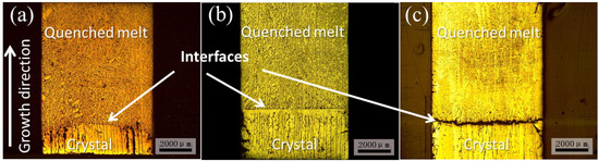
Figure 1. Three forms of solid–liquid interface morphologies under the condition of V = 15 mm/h with different half zone-melting lengths: (a) P = 60; L1/2 = 7 mm (convex); (b) P = 70; L1/2 = 10 mm (flat); (c) P = 80; L1/2 = 15 mm (concave) [19] (here, P is heating power) (Reprinted with permission from Ref. [19]. Copyright 2015 Elsevier).
Generally, solidification parameters, such as the temperature gradient and solidification rate, influence the evolution of texture during the directional solidification process. By comparing the texture at different distances from the onset of solidification, Palit et al. [20] found that the transition in the preferred growth direction from <110> to <112> occurred through intermediate <123> texture components. Furthermore, plane-front solidification morphology and irregular peritectic coupled growth were observed in a wide range of solidification rates (5–80 cm/h), while the preferred direction changed from <311> to <110> to <112> at 5–100 cm/h solidification rates [21]. The {111} planes in Figure 2a were composed of two different types of atomic layers, in which one layer was all Fe, which increased the obstacle of atomic arrangement in the growth process. At the same time, the {311} planes could be attached to the two {111} planes, as shown in Figure 2b. Therefore, although {111} planes had higher atomic bulk density, the preferred orientation at low solidification rates (5–30 cm/h) was <311>. In addition, the highest magnetostriction was achieved in the sample with a solidification rate of 100 cm/h due to the <112> preferred orientation, as shown in Figure 2c,d.
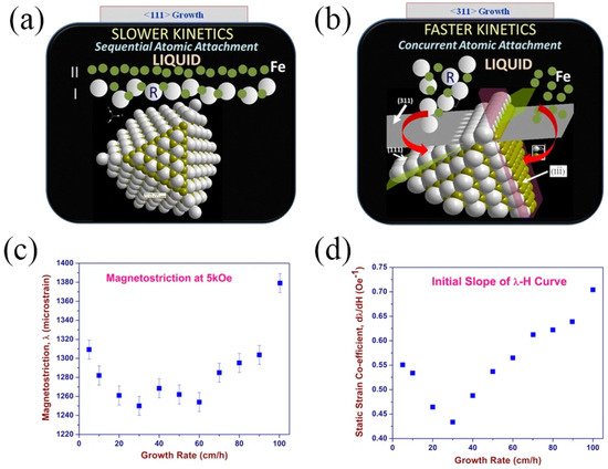
Figure 2. Comparison of atomic attachment kinetics at (a) (111) and (b) (311) interfaces; (c) magnetostriction (λ) of directionally solidified samples measured at an applied field of 5 kOe and (d) the plot of slope (dλ/dH) of the initial λ-H plot, plotted as a function of growth rate [21] (Adapted with permission from Ref. [21]. 2016 Springer Nature).
The growth twins of Tb-Dy-Fe alloys changed the crystal orientation, which was related to the crystal orientation of mirror symmetry [22]. Previous studies have shown that different solidification rates correspond to different solidification morphologies; that is, with the increase in the solidification rate, the preferred axial orientation changed from <101> to <112> and was then reoriented to <101> [23]. Recently, 3D spatial extension and transformation of the whole grain were asserted to be the key to interpreting the transformation of the preferred axial orientation. As a polyhedral material with a face-centered cubic structure, Tb-Dy-Fe alloy dendrites grow in the form of twin-related lamellae. In this case, when the crystal grows in a cellular form, the initial dendritic arms of the <110> axially oriented crystal have two extension directions, which will occupy more space and obtain preferential growth (Figure 3). Therefore, the transformation of the preferred axial orientation was explained by the different space-occupying capacities caused by the different morphological configurations for <101> and <112> axially oriented grains [24].
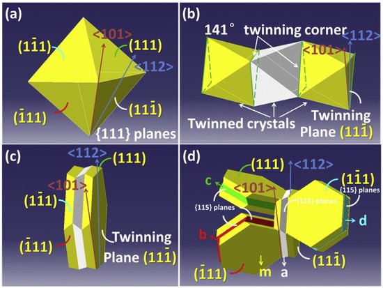
Figure 3. Octahedral configuration: (a) a faceted equiaxed grain m bounded by eight {111} planes; (b) occurrence of double parallel twin boundaries on the (111¯) plane of the crystal; (c) twinned lamellas grow on the (111¯) plane; (d) twinned lamellas grow on four different {111} planes [24]. Reprinted with permission from ref. [24]. Copyright 2018 Elsevier.
2.2. <111>-Oriented Tb-Dy-Fe Alloys Prepared by Directional Solidification in Magnetic Fields
Aiming to prepare Tb-Dy-Fe alloys with preferred orientation along <111> or close to <111>, researchers introduced a strong magnetic field to induce the crystal orientation in a specific direction during the directional solidification process. According to the relevant theory of crystal orientation induced by a magnetic field [25], if there is sufficient action time and rotation space, grains of materials with magnetocrystalline anisotropy will rotate and be oriented under the action of a strong magnetic field through Lorentz force, magnetic force and the magnetic moment of materials.
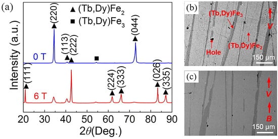
A high magnetic field in the horizontal direction was directly applied to the directional solidification process [26]. Liu et al. [27][28][29][30][31][27,28,29,30,31] obtained a higher <111> orientation and improved magnetostrictive properties by applying a constant magnetic field of 4.4 T during the solidification process of Tb0.27Dy0.73Fe1.95 alloy, as shown in Figure 4. In addition, the best contrast of the domain image and the widest magnetic domain were obtained in the sample prepared under a 4.4 T magnetic field [27]. The required magnetic field in the range of 4–10 T to achieve <111> orientation increased with the increase in the cooling rate [28].
Recently, researchers obtained both orientation and alignment along <111> by multiple magnetic field effects of the liquid phase and solid phase, as shown in Figure 5 [29][30][29,30]. In addition, magnetostrictive and mechanical properties were increased by adjusting the content, morphology and distribution of the (Tb, Dy)Fe3 phase and WSP by coupling directional solidification with a high magnetic field [31].
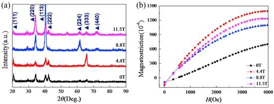
Furthermore, when a gradient magnetic field strongly dependent on the cooling rate was applied during cooling and solidification, magnetic gradient Tb0.27Dy0.73Fe1.95 alloy with gradient magnetostriction and saturation magnetization was obtained, as shown in Figure 6, which was attributed to the increase in the gradient of the orientation degree [32][33][34][32,33,34].
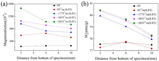
Figure 6. (a) The maximum magnetostriction of alloys solidified in various high magnetic fields at 4000 Oe and (b) saturation magnetization through the depths of alloys solidified in various high magnetic fields [32]. Reprinted with permission from Ref. [32]. Copyright 2016 World Scientific Publishing Company.