As the demand for the real-time monitoring of human motion and physiological information has grown, miniature and intelligent wearable electronic devices have been rapidly developed. Nowadays, a variety of wearable electronic products, such as electronic skins, smart watches and sports wristbands, are becoming an indispensable part of our lives and changing our behavior patterns and lifestyles. Strain sensors are important components of wearable electronic devices, which register and transmit changes in human motion parameters and physical health indicators through electrical signal responses.随着最近对人体运动和生理信息的实时监控的需求不断增长,微型和智能可穿戴电子设备得到了迅速发展。如今,各种可穿戴电子产品,如电子皮肤、智能手表和运动腕带,正在成为我们生活中不可或缺的一部分,并改变着我们的行为模式和生活方式。应变传感器是可穿戴电子设备的重要组成部分,它通过电信号响应记录和传输人体运动参数和身体健康指标的变化。
1. Introduction引言
随着最近对人体运动和生理信息的实时监控的需求不断增长,微型和智能可穿戴电子设备得到了迅速发展。如今,各种可穿戴电子产品,如电子皮肤、智能手表和运动腕带,正在成为我们生活中不可或缺的一部分,并改变着我们的行为模式和生活方式。应变传感器是可穿戴电子设备的重要组成部分,它通过电信号响应[1]记录和传输人体运动参数和身体健康指标的变化。然而,传统半导体或金属传感器[2,3]的刚性限制了与人体曲面的有效相互作用,导致收集的电信号失真或不准确。此外,它们的变形性不足以满足人体的大应变要求[4],因为拉伸在各种变形模式(拉伸,压缩,弯曲,剪切和扭转)[5]下对传感器施加应力和应变。因此,有必要开发柔性和可伸缩的应变传感器。
As the demand for the real-time monitoring of human motion and physiological information has recently grown, miniature and intelligent wearable electronic devices have been rapidly developed. Nowadays, a variety of wearable electronic products, such as electronic skins, smart watches and sports wristbands, are becoming an indispensable part of our lives and changing our behavior patterns and lifestyles. Strain sensors are important components of wearable electronic devices, which register and transmit changes in human motion parameters and physical health indicators through electrical signal responses [1]. However, the rigidity of traditional semiconductor or metal sensors [2][3] limits effective interactions with the curved surface of the human body, resulting in the distortion or inaccuracy of the collected electrical signals. In addition, they are not deformable enough to meet the large strain requirements of the human body [4], as the tensile exerts stress and strain on the sensors in the various deformation modes (tensile, compression, bending, shear and torsion) [5]. Therefore, it is necessary to develop flexible and stretchable strain sensors.
According to the substrate structure, flexible sensors are divided into 1D fiber or yarn strain sensors [6][7][8][9], 根据基材结构,柔性传感器分为一维纤维或纱线应变传感器[6,7,8,9],2D
film [10][11][12], fiber mat [13][14] or fabric [15][16][17][18] strain sensors, and 膜[10,11,12],纤维毡[13,14]或织物[15,16,17,18]应变传感器,以及3D
aerogel [19][20][21] or foam [22][23] strain sensors. Compared with 气凝胶[19,20,21]或泡沫[22,23]]应变传感器。与2D
or 或3D
flexible strain sensors, fiber-based and yarn-based sensors are smaller in size and more flexible to better fit the soft and curved human body, and thus detect subtle movements more accurately. Additionally, the multihierarchy nature of the fiber or yarn structure (fiber-yarn-fabric garment) shows outstanding softness and stretchability, enabling it to deform appropriately when subjected to additional stress or its own gravity. A large number of fibers can also disperse the stress to avoid excessive damage to the device structure. Moreover, they are easy to interconnect with the components of wearable electronics and hide in fabrics with different complex structures. Therefore, fiber or yarn sensors meet the requirements of excellent flexibility, air permeability and comfort for wearable electronic devices due to their advantages of softness, portability, ductility and easy implantation into complex structures. They are more suitable for the development of a new generation of flexible strain sensors. The characteristics of flexible strain sensors with different substrates are summarized in Table 柔性应变传感器相比,基于纤维和基于纱线的传感器尺寸更小,更灵活,可以更好地适应柔软和弯曲的人体,从而更准确地检测细微的运动。此外,纤维或纱线结构(纤维 - 纱线 - 织物服装)的多层性质显示出出色的柔软性和拉伸性,使其在承受额外应力或自身重力时能够适当变形。大量的纤维还可以分散应力,以避免对器件结构的过度损坏。此外,它们易于与可穿戴电子产品的组件互连,并隐藏在具有不同复杂结构的织物中。因此,纤维或纱线传感器由于其柔软性、便携性、延展性和易于植入复杂结构的优点,满足可穿戴电子设备的优异柔韧性、透气性和舒适性的要求。它们更适合于开发新一代柔性应变传感器。表1.
总结了具有不同基板的柔性应变传感器的特性。
Table表 1. Features of flexible strain sensors with different structures.
具有不同结构的柔性应变传感器的特点。
Strain菌株
Sensors传感器 |
Advantages优势 |
Disadvantages弊 |
| Fibers or yarns纤维或纱线 |
Good stretchability and flexibility, and easy to realize accurate detection of joint movement with a single direction.良好的拉伸性和柔韧性,易于实现单向关节运动的精确检测。 |
Poor stability.稳定性差。 |
| Fiber mats纤维毡 |
Good stretchability and permeability.良好的拉伸性和渗透性。 |
Uneasy to integrate into clothing and realize the accurate detection of joint movement with single direction.难以融入服装,实现单向关节运动的精确检测。 |
| Fabrics织物 |
Easy to fabrication with various structures.易于制造各种结构。 |
Poor stretchability, stability and durability.拉伸性、稳定性和耐久性差。 |
| Films电影 |
Good stretchability and easy-to-design patterns.良好的拉伸性和易于设计的图案。 |
Poor permeability, difficult to integrate and unable to accurately detect joint movement with a single direction渗透性差,难以整合,无法准确检测单向关节运动; poor comfort.舒适度差。 |
| Aerogels or foams气凝胶或泡沫 |
Suitable for detect pressure.适用于检测压力。 |
Poor stretchability and hysteresis.拉伸性和滞后性差。 |
According to the sensing mechanism, textile strain sensors are mainly categorized as resistive, capacitive [24][25][26][27], piezoelectric [28][29], inductive [30][31], triboelectric [32], or optical [33]. In terms of fiber- and yarn-based strain sensors, resistive and capacitive sensors are the most widely studied, as shown in Table 根据传感机理,纺织应变传感器主要分为电阻式、电容式[24、25、26、27]、压电式[28,29]、电感式[30,31]、摩擦电式[32]或光学[33]。在基于光纤和纱线的应变传感器方面,电阻式和电容式传感器是研究最广泛的,如表2. Resistive sensors realize strain detection by detecting changes in resistance. They have the advantages of a simple assembly process and easy signal identification, but their linearity is low. Capacitive sensors are composed of a dielectric layer and two electrode layers. The dielectric layer is sandwiched between the two electrode layers and deformed under the applied strain. This kind of strain sensor has a good linear response to strain, but it is easily affected by the environment, considering aspects such as temperature and humidity.
所示。电阻式传感器通过检测电阻的变化来实现应变检测。它们具有组装过程简单,信号识别容易的优点,但线性度较低。电容式传感器由一个介电层和两个电极层组成。电介质层夹在两个电极层之间,并在施加的应变下变形。这种应变传感器对应变具有良好的线性响应,但考虑到温度和湿度等方面,很容易受到环境的影响。本文主要综述了电阻式应变传感器的研究进展。
Table表 2. Features of resistive and capacitive strain sensors.
电阻式和电容式应变传感器的特点。
| Strain Sensor应变传感器 |
Principle原则 |
Gauge Factor仪表系数 |
Benefits好处 |
Drawbacks缺点 |
| Resistive电阻 |
Detection of resistance changes to achieve strain detection (R = ρl/A).检测电阻变化,实现应变检测(R = ρl/A). |
[(R − R0)/R[(R − R0]/ε)/R0]/ε |
Easy to identify signals, wide working strain range, good frequency response characteristics, and high sensitivity.易于识别信号,工作应变范围宽,频率响应特性好,灵敏度高。 |
Poor linearity, poor long-term cycle stability, and high hysteresis.线性度差、长期周期稳定性差、滞后高。 |
| Capacitive电容的 |
Detection of capacitance changes to achieve strain detection (C = ε0εrA/d).检测电容变化,实现应变检测(C = ε0εrA/d)。 |
[(C − C0)/C[(C − C0]/ε)/C0]/ε |
Good linearity, long-term cycle stability, and low hysteresis.线性度好,长期循环稳定性好,滞后低。 |
Limited to working strain range, susceptible to the surrounding environment, and small sensitivity.限于工作应变范围,易受周围环境影响,灵敏度小。 |
There are two common methods for preparing 1D flexible resistive strain sensors. One is to prepare stretchable conductive composite fibers by a spinning method. The other is to coat conductive materials on the surface of a substrate to form stretchable conductive strain sensors by methods such as dip coating, in situ polymerization, layer-by-layer assembly and so on. The performances of strain sensors (in terms of mechanical properties, workable strain range, sensitivity, repeat stability, response time, linearity, etc.) are affected by the conductive materials and elastic matrix, conductive network and yarn structure. Although plenty of studies have been conducted and great progress has been made in the field of flexible strain sensors, most of the reported sensors are far from being implemented in practical applications due to technical obstacles and challenges.制备一维柔性电阻式应变传感器有两种常用方法。一种是通过纺丝法制备可伸缩导电复合纤维。另一种是通过浸涂、原位聚合、逐层组装等方法,在基板表面涂覆导电材料,形成可伸缩的导电应变传感器。应变传感器的性能(在机械性能、可工作应变范围、灵敏度、重复稳定性、响应时间、线性度等方面)受导电材料和弹性基体、导电网络和纱线结构的影响。尽管在柔性应变传感器领域已经进行了大量研究并取得了很大进展,但由于技术障碍和挑战,大多数报告的传感器远未在实际应用中实施。
2. Conductive Materials导电材料
In terms of the resistive flexible strain sensors, the conductivity of conductive materials and the structure of the conductive network not only determine their initial resistances, but also affect the range of resistance variation and the working strain. On the one hand, if the initial resistance of the strain sensor is too large, its resistance will easily increase beyond the range of the test instrument under large strain, which limits the application range of the strain sensor [34]. Additionally, it will cause an excessive static load and large power consumption. Therefore, the initial resistance range of the sensor should preferably not exceed megohms. On the other hand, if the initial resistance of the strain sensor is too small, it can easily be affected by other external resistances, such as interconnected contact resistance, which leads to a lower sensitivity and inaccurate measurement. Apart from the electrical resistance, the stability and the compatibility with the elastic matrix should also be considered when conductive materials are selected. At present, the common conductive materials include intrinsic conducting polymers, such as polypyrrole (就电阻式柔性应变传感器而言,导电材料的电导率和导电网络的结构不仅决定了它们的初始电阻,还影响电阻变化的范围和工作应变。一方面,如果应变传感器的初始电阻过大,其电阻在大应变下很容易超出测试仪器的范围而增加,从而限制了应变传感器的应用范围[34]。此外,它还会导致过大的静负载和大功耗。因此,传感器的初始电阻范围最好不要超过兆欧。另一方面,如果应变传感器的初始电阻太小,则很容易受到其他外部电阻的影响,例如互连的接触电阻,从而导致灵敏度较低和测量不准确。除了电阻外,在选择导电材料时,还应考虑稳定性以及与弹性基体的相容性。目前,常见的导电材料包括本征导电聚合物,如聚吡咯(PPy
) [35], polyaniline ()[35],聚苯胺(PANI
), polythiophene (),聚噻吩(PTh
) and PEDOT:)和PEDOT:PSS
[36];
advanced carbon-based materials, such as carbon black (先进的碳基材料,如炭黑(CB
) [37], carbon nanotubes ()[37],碳纳米管(CNTs
) [38][39][40] and graphene ()[38,39,40]和石墨烯(Gr
) [4][41])[4,41];
metal materials, such as gold (金属材料,如金(Au
) [42], silver ()[42],银(Ag
) [43][44][45], copper ()[43,44,45],铜(Cu
) [46][47] and liquid alloys [48])[46,47]和液体合金[48];
and a new transition metal carbon和一种新的过渡金属碳/
nitride 2D nano-layered material, MXene [16][49]. The characteristics of each conductive material are summarized in Table 氮化物2D纳米层材料,MXene[16,49]。表3.
总结了每种导电材料的特性。
Table表 3. Common conductive materials and their characteristics [4][50][51][52][53][54].
| Types类型 |
Conductive Materials导电材料 |
Conductivity (电导率(S/cm)厘米) |
Characteristics特性 |
| Conducting polymers导电聚合物 |
PPy断续器 |
2000 |
Solution processability, low-temperature synthesis route.溶液加工性,低温合成路线。 |
| PANI聚 苯胺 |
112 |
| PTh |
560 |
| 佩多特:PEDOT: PSS |
4700 |
| Carbon based碳基 |
CB断续器 |
1000 |
Light, good chemical and thermal stability, difficult to disperse.重量轻,化学和热稳定性好,不易分散。 |
| CNT断续器 |
3.8 × 10⁵ |
| Gr |
7200 |
| Metal |
Au |
4.10 × 10⁷ |
Excellent electrical conductivity, brittle, heavy, poor interface compatibility. |
| Ag |
6.31 × 10⁷ |
| Cu |
5.96 × 10⁷ |
| EGaIn |
4.8 × 10⁵ |
| Transition metal carbon/nitride material |
MXene |
4600 |
Hydrophilicity, good biocompatibility, but expensive, easy to oxidize. |
2.1. Conducting Polymer
Conducting polymers have a conjugated long-chain structure and the delocalized π electrons on the double bond migrate to the molecular chain to form a current, and thus the material exhibits conductivity. Due to the general solubility of their corresponding monomers, conducting polymers can be formed in situ in a soft polymer matrix and are flexible in processing and compatible with elastomeric polymers. However, their charge/discharge stability and ramp voltage are low, since the electron transfer of the conducting polymers are controlled by the doping concentration (10–50%). The conductivity of conducting polymers is much lower than that of metal. Furthermore, conducting polymers are more brittle and rigid than linear aliphatic polymers, because their π-conjugated main chain structure is composed of olefin bonds or aromaticity
[55]. Seyedin et al. reported PU/PEDOT: PSS elastomeric composite fibers by a wet-spinning method and their resistance shifted towards higher resistances with the increase in the stretching–releasing cycle period
[56]. In actual applications, the stability of conducting polymers is not good enough, especially doping materials when considering air oxidation stability. Therefore, the combination of conducting polymers and carbon-based nanomaterials as conductive sensing materials is another used method
[57]. For example, Li et al. proposed a wearable strain sensor by using thermoplastic polyurethane fibers as the core support, aligned and interconnected carbon nanotubes in the sub-outer layer as conductive filaments and the outer layer of PPy coating as the cladding layer
[58]. It has a wide detectable range (from 0.1% to 50% tensile strain) and performs a multichannel detection of deformation capabilities (tension, bending and torsion). Wu et al. prepared a PEDOT: PSS/CNT/TPU composite fiber strain sensor by dip coating. In this layered microstructure, PEDOT: PSS is used as a sensing material to reduce the initial resistance and improve the sensitivity of the sensor, while the CNT aggregate acts as a conductive bridge to ensure conductivity at large strains, providing a larger sensing range for the sensor
[59].
2.2. Carbon-Based Materials
Carbon-based materials with excellent conductivity and multidimensional structures are suitable for manufacturing large-strain, high-sensitivity flexible strain sensors. Seyedin et al. used a variety of conductive fillers (such as spherical CB, rod-shaped SWCNTs and chemically converted Gr sheets) to prepare different conductive fibers by wet-spinning technology
[60]. It was found that the electrical and mechanical properties of composite fibers depend on the length and the length-diameter ratio of fillers as well as the interaction between the fillers and the elastomer. Overall, CB has a lower cost and better dispersion than CNTs and graphene. Doping CB in CNTs and Gr can improve sensor performance while reducing manufacturing costs. For example, Zhang et al. prepared a simple and low-cost strain sensor by sequentially coating CNTs and CB on the PU yarn by a layer-by-layer assembly method
[61]. Under small strain, the conductive network of the CB layer breaks, while the conductive network of the CNT layer does not break until a large enough strain is reached. The CB layer and CNT layer rupture successively with strain, so that the sensor exhibits super stretchability and a large linear range (15–150%). Compared with CNTs with a high length-diameter ratio, 0D CB has a higher degree of freedom of deformation, so the point-to-point conductive network will be destroyed more obviously during the stretching process, giving the strain sensor better sensitivity
[62][63][64][62,63,64].
CNTs tend to aggregate and entangle with each other when mixed with polymers due to the high length-diameter ratio and large specific surface area. Consequently, it is difficult for them to uniformly disperse in the polymer matrix, not allowing for the excellent conductivity they show in composite fibers. In addition to using dispersants, CNTs can also be modified with polar functional groups, such as carboxyl (-COOH) and hydroxyl (-OH), to improve the dispersibility and adhesion of CNTs in the matrix. However, the graphitized structure of CNTs will be destroyed, resulting in a decrease in electrical conductivity
[65], and the same is true for reduced graphene oxide. Compared with CNT sensors, graphene-based strain sensors generally have a higher sensitivity and lower sensing strain due to their small size, sheet-like structure, which is easy to slide, and poor stretching ability. Therefore, appropriate materials should be selected according to the actual requirements in terms of prepared strain sensors. Additionally, the viscoelasticity of the stretchable substrate and the fracture of the carbon material will cause the hysteresis of the sensor under large strain
[66], leading to a low sensitivity and poor repeatability and stability. In summary, it is still a challenge to manufacture flexible carbon-based strain sensors with good sensitivity and a broad strain range at low cost.
2.3. Metal-Based Materials
For flexible strain sensors, low-dimensional metal nanostructures are very attractive due to their excellent electrical conductivity. In general, silver has better conductivity and stability than copper, and has a lower cost than other precious metals, such as gold. Copper nanowires (CuNWs) are considered as a promising alternative to silver nanowires (AgNWs) due to their comparable electrical and thermal conductivity, abundance and low cost. However, CuNWs have high inherent resistance and contact resistance due to their sensitivity to oxygen and moisture
[47]. In addition, liquid metal has been used to prepare strain-sensing yarns. Zhu et al. reported super-stretched conductive fibers by injecting liquid alloy (EGaIn) into hollow SEBS fibers
[48]. Due to the electrical continuity of the liquid metal, the fiber can maintain a certain degree of conductivity at a strain of more than 700%. Additionally, its resistance change mainly depends on the real-time geometrical size change when the fiber is stretched, showing less hysteresis and a higher durability. However, the limitation of this method is that the liquid core of the fiber will collapse under concentrated pressure or large strain, although the conductivity can be restored.
Metal nanomaterials can be assembled on the surface of fibers or yarns by methods such as in situ reduction, sputtering, electrochemical deposition and chemical deposition
[67]. However, the bonding force between the conductive coating and the polymer fiber layer is usually poor, and the conductive coating easily peels off due to mechanical deformation, resulting in poor stability. Another method is to prepare stretchable conductive composite fibers by filling metal nanomaterials into a polymer matrix with elasticity through traditional spinning technology. However, the poor dispersibility of metal nanomaterials in the polymer matrix can easily lead to the clogging of the spinneret and poor performance of the composite fiber. To solve this issue, Lu et al. proposed using surface-modified AgNWs and elastic polyurethane (PU) to prepare stretchable conductive composite fibers, in which polyethylene glycol (PEG) derivatives were used to modify the surface of AgNWs
[43]. The compatibility between the PU and AgNWs was remarkably improved, resulting in a high filling load and the effective dispersion of AgNWs in the PU. It was found that the electrical conductivity of the yarn without surface modification is 147 S/cm, while the electrical conductivity of the yarn with modified AgNWs was 331 S/cm. Although metal nanomaterials can realize the preparation of flexible electronics with good electrical conductivity, metal-based strain sensors are prone to failure due to the fragility and weak interfacial forces of metal. Therefore, it is worth make efforts to enhance interfacial adhesion, such as the improvement of the interactions between metal nanoparticles and fiber functional groups.
2.4. MXene
MXene has shown good potential in the field of wearable electronics due to its excellent properties, such as metal-like electrical conductivity, large specific surface area, excellent thermal conductivity, layered structure, etc. [68]. In addition, it has good dispersibility in aqueous solutions due to the large number of functional groups formed on the surface of MXene by hydrofluoric acid etching. Therefore, it is suitable for modifying textiles through solution processing methods. However, exposure to high humidity or air may cause the oxidation of MXene, thereby reducing its various properties, especially electrical properties [16][49]. For example, Gong et al. developed a spandex composite yarn sensor with a composite coating using MXene nanosheets as “bricks” and PDA/NiMXene has shown good potential in the field of wearable electronics due to its excellent properties, such as metal-like electrical conductivity, large specific surface area, excellent thermal conductivity, layered structure, etc. [68]. In addition, it has good dispersibility in aqueous solutions due to the large number of functional groups formed on the surface of MXene by hydrofluoric acid etching. Therefore, it is suitable for modifying textiles through solution processing methods. However, exposure to high humidity or air may cause the oxidation of MXene, thereby reducing its various properties, especially electrical properties [16,49]. For example, Gong et al. developed a spandex composite yarn sensor with a composite coating using MXene nanosheets as “bricks” and PDA/Ni2+ as “mortars” through alternate dip-coating methods [69]. The yarn strain sensor has high sensitivity, a low detection limit (0.11%) and a wide sensing range (0.11–61.2%). However, due to the poor oxidation stability of MXene in water, the conductivity of the yarn gradually deteriorates at a temperature of 30–50 °C over a 20 h washing cycle.
3. Fabrication and Structure Design
Fiber- and yarn-based strain sensors are mainly manufactured by spinning and coating. For example, the conductive filler is mixed into the spinning solution to prepare conductive composite fibers. The structure of composite fibers prepared by spinning is round with uniformly distributed conductive materials, or coaxial, porous, hollow, and so on. In terms of coating conductive materials on fibers and yarns, the conductive coating can be designed as a microcrack, fold buckling, multilayer composite structure. Additionally, the geometry of the yarns was designed to control the sensing performance of strain sensors. These preparation strategies and structural design features will be discussed in the following sections. The performances of fiber and yarn strain sensors reported in the literature are summarized in
Table 4,
Table 5 and
Table 6.
3.1. Conductive Composite Fibers
3.1.1. Uniform Mixing of Conductive Materials
Traditional spinning techniques, such as wet spinning, dry spinning and melt spinning, are the most common methods to prepare a 1D stretchable conductive composite materials; they mix the conductive filler and the elastic matrix directly and uniformly, and then extrude it through the spinneret hole to a coagulating bath to form the composite fiber. Li et al. uniformly mixed Gr into SBS and prepared SBS/Gr composite fiber flexible strain sensors by a simple wet-spinning method, and the Gr content had a significant impact on the morphology, mechanical properties and electromechanical properties of the composite fiber (
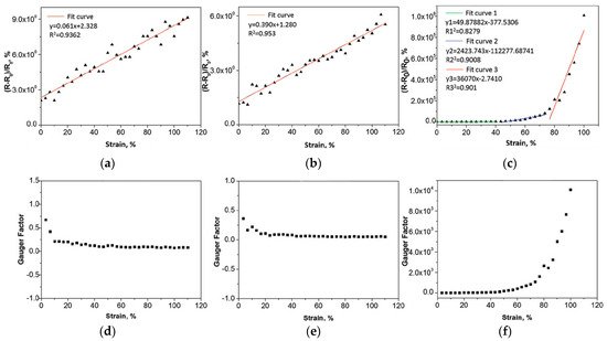
Figure 1)
[70]. The fiber with the 5 wt% graphene content has a wide working strain, which reaches 100%. However, its sensitivity increases with the increase in strain, and the sensitivity within 50% strain is changeable at different stretching speeds. He et al. proposed multiwalled carbon nanotube/thermoplastic polyurethane (MWCNT/TPU) fibers by wet spinning
[71]. The gauge factors (GF) of the MWCNT/TPU fiber are about 550 and 2800 in the strain ranges of 1 to 4% and 5 to 100%, respectively. The strain of the MWCNT/TPU fibers decreases significantly under large hysteresis after multiple stretching–releasing cycles, indicating poor sensing repeat stability. At the same time, the influence of different weight ratios of MWCNTs to TPU on the mechanical and electrical properties of composite fibers has been studied. It was found that the concentration and arrangement of MWCNT would change the working strain range and GF of the sensor
[72]. Wang et al. manufactured a fiber strain sensor with a wide response range (320%) and a fast response time (<200 ms) based on MWCNTs and TPU by a simple wet-spinning method
[39]. However, the electrical response of the MWCNT/TPU strain sensor decreased slightly in the initial stage when multiple stretching–releasing cycles were carried out at 100% strain, and it exhibited unstable sensitivity at the same time. To improve the conductivity and the stability of the conductive network, hybrid conductive fillers have been used to achieve a composite synergistic effect to prepare strain-sensing fibers. For instance, Zhang et al. demonstrated a highly conductive AgNW/MWCNT/TPU composite fiber by wet spinning, in which MWCNTs were regarded as the sensitive materials and silver nanowires were used to improve electrical conductivity
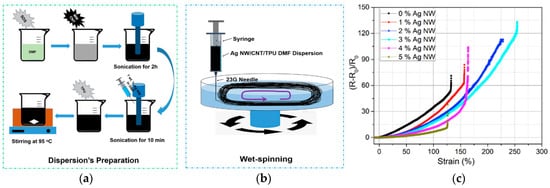
[73]. When the contents of AgNWs reached the optimal amount (3%), the working strain range was 254%, and the conductivity was 0.0803 S/cm (
Figure 2). Compared with single-filler composite fibers, the increase in AgNWs improves the conductivity and working strain range of the composite fiber, but its sensitivity decreases. In the case of a strain range of 50–150%, the relative resistance change of the sensor continues to decrease in stretching–releasing tests within 1000 s, showing poor stability.
Figure 1. ΔR/R0–strain curve and GF–strain curve of SBS-xGr composite fiber with different graphene contents. (a,d) SBS-1Gr composite fiber; (b,e) SBS-3Gr composite fiber; (c,f) SBS-5Gr composite fiber [70].
Figure 2. (
a) Suspension preparation process; (
b) AgNW/MWCNT/TPU spinning process; (
c) the relative change resistance–strain curve of the fiber strain sensor with different AgNW contents
[73].
3.1.2. Selective Localization of Conductive Materials
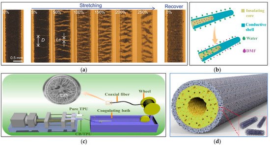
The conductive network was also designed by controlling the distribution of the fillers, such as selective positioning in multiple phases to form a co-continuous structure or a sea-island structure. In this case, the conductivity of the composite is improved by forming a double or triple permeation structure in the polymer matrix. The selective positioning of the fillers at the interface of the co-continuous polymer structure can further reduce the filler content, which is required to form the continuous conductive network. Zhou et al. used the coaxial wet-spinning method and post-treatment process to prepare the thermoplastic elastomer/single-walled carbon nanotube (TPE/SWCNT) ribbon coaxial fiber with good stretchability and high sensitivity (
Figure 3a)
[38]. The strain sensor composed of this fiber has a GF of 48 at 0–5% strain and a GF of 425 at 20–100% strain; a linear change cannot occur in in the full strain range. Tang et al. designed a stretchable core sheath fiber using a one-step coaxial wet-spinning assembly method, in which a high-stretch polymer elastomer Ecoflex wrapped CNT/Ecoflex composite material
[74]. Similar to traditional cables, the outer insulating sheath effectively avoids short circuits and the falling off of conductive fillers. At the same time, it can have good conductivity under a low permeability threshold (0.74 vol%). Strain sensors made of this fiber achieve a high sensitivity of 1378 under 300% strain and show high durability under 100% strain, but they exhibit low sensitivity in a small strain range, non-linear resistance change and obvious overshoot behavior. Yue et al. demonstrated a highly stretchable TPU-CB@TPU fiber strain sensor with a porous core–sheath structure through the coaxial wet-spinning method (
Figure 3b,c)
[37]. Due to the countercurrent diffusion and coagulation of the solvent, this fiber has a porous structure with a wide strain range. The highest GF is 28,084 when the strain is 204%. However, its sensitivity is not large enough in a small strain range, and the resistance change gradually declines over multiple cycles of stretching. A coaxial fiber with an outer layer of MXene/PU composite and an inner layer of PU was prepared by Seyedin et al.
[75]. Compared with the non-coaxial composite fiber, the coaxial fiber shows a larger strain range, a smaller data drift, and an improvement in the cyclic stability of the sensor response. Gao et al. fabricated a coaxial stretchable composite fiber with a double-layer hollow structure (
Figure 3d), in which the conductive outer layer has a CNT/TPU composite as the sensitive area, and the insulating inner layer is made of pure TPU with a hollow core to serve as a flexible support
[76]. The prepared composite fiber (TPU-8CNT@TPU) has an ultralow percolation threshold (0.17 wt%), good durability, and small compression deformation that can be detected. With an increase in the stretching speed, the relative resistance differently changes under the same strain. Additionally, there is an obvious shoulder phenomenon, which may disturb signal identification in an accurate strain monitoring. However, the reason for this shoulder phenomenon is still not clear. The mainstream is attributed to the competition between the destruction and reconstruction of CNT conductive networks in the fiber, which needs further verification.
Figure 3. (
a) The image of a typical coaxial fiber stretched from 0 to 250% strain and relaxed after unloading; D and Lc are the average crack spacing and the average crack opening displacement, respectively
[38]. (
b) Fiber cell structure evolution process (
c) Schematic diagram of the TCTF preparation process
[37]. (
d) Schematic diagram of TPU-8CNT@TPU structure
[76].
The characteristics of various fiber-based strain sensors prepared by spinning technology are summarized in
Table 4. In general, the preparation of stretchable conductive composite fibers as strain sensors by mixing conductive materials and spinning is a process technology that can be produced on a large scale and is widely used in industry. However, the addition of conductive filler will enhance the rigidity of the elastic matrix, and shrink the tensile strain range of the fiber, which leads to the narrow working strain range of the fiber sensor. On the contrary, if the amount of conductive material is too low, the conductivity of the composite fiber will also limit its working strain range. Therefore, there is a paradox between the conductivity and the working strain range of the stretchable conductive fiber, which needs to be balanced. According to the percolation theory
[60][77][78][79][80][81][60,77,78,79,80,81], the content of conductive materials in stretchable conductive composites has a percolation threshold. When the percolation threshold is exceeded, the polymer elastomer changes from an insulator to a conductor, and the conductivity increases with the increase in the content of conductive materials. When the content is near the percolation threshold, the sensitivity of the material is at its greatest
[82]. Therefore, it is still a huge challenge to achieve a high strain range and high sensitivity at the same time for conductive composite fibers. In addition, there is a limit on the production costs of practical commercial applications with the increase in conductive fillers. To reduce the permeation threshold while achieving high conductivity, different strategies have been studied
[50][83][84][50,83,84], such as functionalizing conductive fillers’ surfaces, increasing the aspect ratio of fillers, controlling the arrangement of fillers, and using different mixture of fillers. However, such permeation-based composite strain sensors rarely exhibit good linearity. When the composite fiber is stretched, its resistance is mainly caused by changes in geometry and tunnel theory
[37][39][85][37,39,85]. With an increase in tunneling distance and the destruction of the conductive path, the resistance of composites increases significantly during the tensile process. The maximum GF usually occurs when the conductive material content is close to the permeation threshold. Other shortcomings of strain sensors made of composite fibers include hysteresis, fatigue and so on, which are mostly due to the viscoelasticity and elastic recovery rate of composite fibers.
Table 4.
Characteristics of conductive composite fiber-based strain sensors prepared by spinning technology.
| Structure |
Substrate |
Sensitive
Materials |
Breaking Stress and Strain |
Conductivity |
Strain Range |
GF |
Repeatability |
Linearity |
Response Time |
Ref. |
| Monofilament |
SBS |
Gr |
10.16 MPa; 910.83% |
N/A |
100% |
10,083.98 (73–100%) |
2500 (20%) |
N/A |
N/A |
[70] |
| Monofilament |
TPU |
MWCNTs |
28 MPa; 320% |
N/A |
100% |
2800 (5–100%) |
N/A |
N/A |
N/A |
[71] |
| Monofilament |
SIBS |
P3HT |
11.4 MPa; 975% |
0.38 S/cm |
770% |
20 (12.25%) |
N/A |
N/A |
N/A |
[86] |
| Monofilament |
TPU |
MWCNTs/
AgNWs |
32.49 MPa |
0.803 S/cm |
250% |
13 (50–150%) |
N/A |
N/A |
N/A |
[73] |
| ] |
| Porous |
TPU |
CB |
2.15 MPa |
N/A |
380% |
28,084 (204%) |
11,000 (60%) |
N/A |
200 ms |
[87] |
| Coaxial |
PU |
MXene |
20.3 GPa |
N/A |
152% |
238 (50%) |
1000 (50%) |
N/A |
N/A |
[75] |
| Hollow |
TPU |
CNTs |
2.92 MPa; 476% |
N/A |
>350% |
1344.1 (200%) |
10,000 (100%) |
N/A |
167 ms |
[76] |
3.2. Conductive Coated Fibers
3.2.1. Microcrack Structure
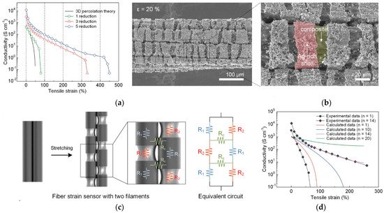
Coating conductive materials on stretchable fibers or yarns is another way to prepare one-dimensional strain sensors by dipping, spraying, and in situ chemical polymerization, etc. The dip-coating method is one of the easiest and most widely used methods among them, due to its simple, fast and cost-effective characteristics. For example, Lee et al. reported a conductive PU multifilament coated uniformly AgNPs by an in situ reduction method, with low initial resistance (0.16 Ω/cm) (Figure 4a,b) [45]. AgNPs are uniformly distributed inside the multifilament and form a dense shell on the outer layer. The GF of the strain sensor reaches about 9.3 × 10⁵ (under 450% strain) when the strain sensor is first stretched, while the GF decreases to 659 (under 450% strain) after subsequent stretching. Although the strain sensor has high sensitivity and wide strain range, its sensitivity is unstable and its linearity is poor. Generally speaking, the microcrack structure constructed by the strain sensor in tension is an effective method to achieve a sensing response and high sensitivity of sensors. However, the microcrack structure is usually limited by strain range. Compared with monofilament, the increase in the number of multifilament structures greatly widens its working strain range according to the theory (Figure 4c,d) [45]. Eom et al. first polymerized conductive PEDOT on polyester (PS) fibers by in situ polymerization to prepare conductive coated fibers, and then embedded this conductive fiber into fabrics to manufacture textile-based strain/touch/pressure sensors and user interface (UI) equipment [36]. Due to the multifilament structure of its PEDOT/PS fiber, the resistance of the sensor tends to fall with the increase in strain, which is contrary to the common trend. During stretching, the overall conductivity of the PEDOT/PS multifilament increases, and the PEDOT/PS monofilament exhibits the opposite behavior. Liu et al. designed a monofilament strain sensor with a beaded structure using the Plateau–Rayleigh instability principle. The way to control the strain distribution along the fiber axis is by adjusting the size of the microbeads and the distance between the microbeads (Figure 5) [88]. This design effectively causes strain concentration and amplifies the local strain. Compared with a single uniform monofilament, the sensitivity of the sensor with a beaded structure is significantly improved. Overall, the sensitivity of the sensor with the crack effect usually increases significantly and then decreases, which is a characteristic of nonlinear sensing [45]. Due to the destruction and shedding of the conductive layer, the sensor also exhibits a certain amount of hysteresis and poor cycle stability.
Figure 4. (
a) The electrical conductivity of the sensor under different strains; (
b) SEM images of the fiber strain sensor at ε = 20%; (
c) the resistance model of the double-filament strain sensor and the corresponding equivalent circuit; (
d) the relationship between the electrical conductivity of the single-filament/multifilament fiber strain sensor and the tensile strain;
n is the number of multiple filaments in the fiber strain sensor
[45].
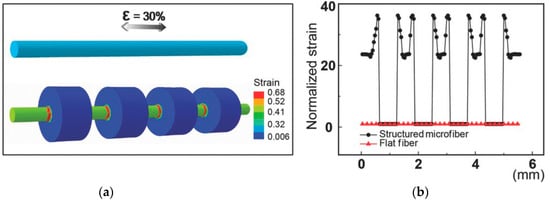
Figure 5. (
a) Finite element simulation to study the strain adjustment effect of microstructured fibers compared with flat fibers; (
b) the strain distribution of different structures along the fiber surface
[88].
3.2.2. Wrinkle Structure
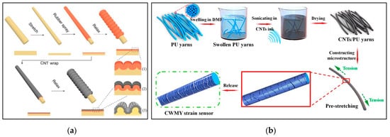
In order to improve the workable strain range, a conductive coating with a wrinkle structure was added to the fiber surface to design a flexible strain sensor. Wang et al. designed a highly stretchable NTSm@rubber@fiber strain sensor with a dual-sheath buckling structure by the pre-stretching method, in which NTS is the carbon nanotube sheets and m represents the number of NTS layers (
Figure 6a)
[89]. The elastic support fiber coaxially coated a curved rubber intermediate layer and a curved NTS conductive layer. At the same time, the GF of the sensor was controlled by changing the manufacturing parameters to adjust the buckling structure, but its overall sensitivity values were very low, only 0.5 (0–200%) and 0.14 (200–600%). The design of a wrinkle structure makes the strain sensor bear high tensile deformation without destroying the conductivity of the material, thereby increasing its sensing range. However, it also causes a small resistance change in the stretched state, showing lower sensitivity. As shown in
Figure 6b, CNT ink/PU yarns with a wrinkle-assisted crack microstructure were created by Sun et al.
[90]. The yarn sensors have an ultralow detection limit and excellent repeat stability. As mentioned above, the complex and multistep manufacturing process poses challenges to realize a large-scale production of strain sensors.
Figure 6. (
a) The manufacturing steps of NTS m @rubber@fiber, the longitudinal cross-sections of the fibers of different manufacturing steps are shown below the rubber fiber. Yellow, red and gray are used for SEBS core, SGE layer and NTS sheath, respectively
[89]. (
b) Schematic diagram of preparation of WCMYSS
[90].
3.2.3. Multilayer Structure
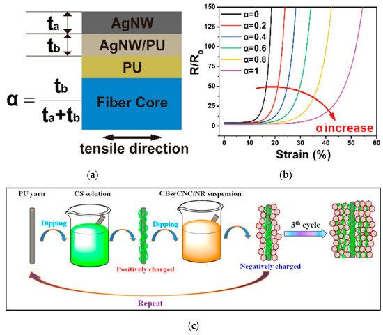
Building a multilayered structure at the fiber scale is another way to design flexible strain sensors. Cao et al. introduced a AgNW/PU fiber with a composite multilayer structure by using an adhesive layer with adjustable adhesion to adjust the interface adhesion and fiber microstructure (
Figure 7a)
[91]. The GF and stretchability of the strain sensor were adjusted by changing the interface layer combination (
Figure 7b). However, its sensitivity was weak and the resistance response was nonlinear. After 100 and 1000 cycles of stretching at 10% strain, the drift rate values of the relative resistance of the sensor were 29.4 and 53.1%, respectively, showing poor repeatability. Liu et al. reported the silver plating polyurethane filaments (SPPF) with good electrical resistivity (4.5 ± 0.1 Ω/cm)
[92]. These AgNPs are bound to the surface of the filament by polydopamine, which remarkably improves the bonding between the conductive material and the fiber interface, but the nonlinear error and hysteresis of the SPPF strain sensor are up to 29.3 and 34.3%, respectively.
Figure 7. (
a) Schematic diagram of the longitudinal section of Ag NW/PU fiber (
b) Modeling of the resistance change and strain of Ag NW/PU fiber with different interface bonding strengths
[91] (
c) Schematic of the preparation of CPC@PU yarn by the LBL assembly process
[34].
The layer-by-layer (LBL) assembly method has been used to develop strain sensors with multilayer structures. The LBL assembly method has been reported as an effective method for manufacturing carbon-based films. Instead of simple deposition, this process includes repeated immersion and evaporation, and various reactions such as electrostatic interactions, hydrogen bonding, or covalent bonding to enhance the adhesion of the interface [93]. Li et al. prepared a strain sensor using graphene/polyvinyl alcohol (Gr/PVA) composite material as the outer layer conductive sheath and polyurethane as the elastic core fiber [94]. When the Gr concentration is 1wt% and the number of coatings is nine, the composite coated fiber has the maximum GF (86.9) and a wide strain range (50%) and good linearity (R2 = 0.97). However, the GF of the strain sensor only reaches more than 40 in the 50% strain extension–release cycles, and the repeatability is 1.81% and the hysteresis error is 9.08% over 100 cycles. A CPC@PU yarn strain sensor was prepared by Wu et al. (Figure 7c) [34], in which the ultrathin conductive CPC layer consists of positively charged chitosan (CS) and negatively charged carbon black (CB)/cellulose nanocrystal (CNC)/natural rubber (NR) nanohybrid. Although this fiber sensor based on CPC coating detects strains as low as 0.1% and shows a GF of approximately 38.9 at 1% strain, it is not reliable for detecting strains larger than 5%. Li et al. proposed a core–sheath structure strain sensor, which is composed of PU core yarn, a highly conductive multilayer sheath material, namely graphene nanosheets/thin gold film/graphene nanosheets (GNSs/Au/GNSs), and PDMS coating. This multilayer structure combination can simultaneously achieve high sensitivity, wide strain-sensing range and good waterproof performance. In 10,000 stretch–release cycles at 50% strain, its stability is excellent [42]. Although the LBL method improves the adhesion of the coating, it takes multiple cycles of treatment to achieve a high conductivity due to the introduction of the insulating polymer.
The characteristics of fiber strain sensors prepared by coating technology are summarized in
Table 5. In general, the coating method is easy to implement and the 1D strain sensors produce via this method show good sensing performance. As the mechanical properties of conductive coatings and elastic substrates are inconsistent, conductive coatings propagate small and dense microcracks, which destroys conductive networks and causes the changes of resistance. However, the poor adhesion and the mechanical mismatch between the elastic substrate and the conductive coating often leads to degradation of the sensor response. Therefore, it is still a big challenge to achieve high linearity and cycle stability by a simple coating. Due to the irreversible fracture and shedding of the conductive layer, it is very necessary to explore the stress distribution and interface strength between the conductive coating and the substrate. Although the added adhesive (like the LBL method) has improved adhesion, the fatigue durability of the strain sensor is still a challenge. Additionally, there is a lack of systematic studies on how to control the crack propagation and stability, and on how it affects the sensing performance of strain sensors.
Table 5.
Characteristics of fiber strain sensors prepared by coating technology.
| Method |
Structure |
Substrate |
Adhesive |
Sensitive Materials |
Breaking Stress and Strain |
Conductivity |
Strain Range |
GF |
Repeatability |
Linearity |
Response Time |
Ref. |
| In site reduction |
Multifilament |
PU |
N/A |
AgNPs |
N/A |
0.16 Ω/cm |
200% |
659 (150–200%) |
10,000 (10%) |
N/A |
N/A |
98]. The yarn sensor has high conductivity and a wide range of stretchable strain. However, the resistance change does not increase monotonously with the increase in strain, instead of a downward trend after 40% strain. In addition, the relative resistance changes in PET/AgNW/PDMS yarns with an upward trend show relatively instability during multiple stretching and bending cycles. Pan et al. designed a yarn sensor with a core–sheath yarn structure, in which a braided composite yarn coated with CNTs is used as the core (BYs-CNT) and electrospun polyurethane nanofibers are used as the sheath
[35]. This kind of combination of the yarn has extremely high sensing sensitivity (maximum GF up to 980) and long-term stability, but poor linearity. Additionally, the yarn preparation process is complicated and cannot be easily produced en masse. Similarly, the relative resistance change shows a downward trend after the strain exceeds 40%, due to the changes in the braid angle and contact area of braided yarns PET during the stretching process.
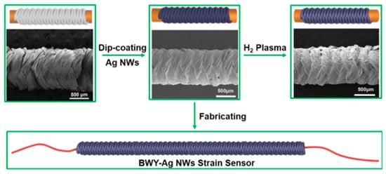
Figure 9.
Schematic diagram of the manufacturing process of the BWY-Ag NW strain sensor [97].
3.3.3. Helical and Winding Structure
In addition to fancy yarn, unconventional yarn sensors have been formed by twisting and winding conductive coated films, which remarkedly enhance the tensile strain range of one-dimensional sensors. Compared with the conventional planar wave structure, the coil structure has greater stretchability because the local stress is suppressed during the stretching process and the local maximum strain is reduced due to the non-planar motion of the coil
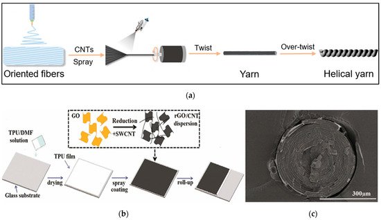
[99]. Ultrahigh stretchable conductive helical yarn with CNT/PU nanocomposite fiber helical yarn was prepared by simple electrospinning, spraying and twisting processes (
Figure 10a)
[99]. With the help of the synergistic effect of the flexible polymer chain and the nanofiber spiral coil structure, the CNT/PU helical yarn will break the limitation of material stretchability due to its rigidity and excellent stretchability. Its recovery is within 900% strain, and the maximum of tensile elongation can reach 1700%, while its sensitivity is very low. Xie et al. designed a SWCNT-RGO/TPU spiral layered composite yarn by spraying and winding technology (
Figure 10b,c)
[100]. Due to the special spiral layered structure of the composite yarn, the conductive layer is wrapped and protected by the elastic polymer layer, and there is no obvious interruption or crack on the surface of the yarn. Compared with the SWCNT-RGO/TPU thin-film sensor, the yarn sensor has a wider working strain range and has five linear regions. In the 50% tensile strain cycles, the relative resistance of the sensor continued to increase during the initial 100 cycles and then began to stabilize.
Figure 10. (
a) Schematic diagram of the preparation of helical CNT/PU yarn
[99] (
b) Schematic diagram of the preparation of SWCNT-RGO/TPU strain sensor (
c) SEM image of spiral layered SWCNT-RGO/TPU yarn
[100].
The performance of yarn-based strain sensors with different structures are summarized in
Table 6. On the basis of the coating, improving the linearity and stability of the strain sensor by changing the yarn structure is an excellent method because the resistance change mainly depends on the structure of the composite yarn. For example, in terms of wrapped yarn-based sensors, the decrease in the contact of the spiral winding leads to an increase in resistance, but this also reduces the sensitivity and working strain range to a certain extent. Therefore, it is necessary to discuss the influence of structural changes on the sensing performance so that the yarn strain sensor has balanced performance indicators.
Table 6.
Characteristics of various yarn-based strain sensors.
| Method |
Structure |
Substrate |
Sensitive Materials |
Breaking Stress and Strain |
Conductivity |
Strain Range |
GF |
Repeatability |
Linearity |
Response Time |
Ref. |
| Dip coating and in situ polymerization |
Core-spun yarn |
PU/cotton |
CNT/PPy |
>7 N; >300% |
310 Ω/cm |
350 |
5.11 (0–50%); 3.41 (50–100%) |
N/A |
Linearity at 0–50% and 50–350% strain, respectively |
N/A |
[95] | [45] |
| In situ polymerization |
Multifilament |
PS |
N/A |
PEDOT |
0.813 ± 0.057 GPa |
600 Ω/cm |
70% |
0.244 (70%) |
1000 (20%) |
N/A |
N/A |
[36] |
| Dip coating |
Wrapped yarn |
PU/PE |
Gr |
29.14 MPa; 676% |
0.012 S/m |
0.2–100% |
3.7 (50%) |
10,000 (30% and 50%) |
N/A |
<100 ms |
[96] |
deposition |
Beaded |
| ELD |
Wrapped yarn | PDMS |
N/A |
Au/CNTs |
N/A |
N/A |
125% |
low |
5000 (30%) |
PUR2 = 0.96 |
N/A |
Cu[88] |
| N/A |
0.2 Ω/cm |
50% |
N/A |
5000 (50%) |
Good linearity |
N/A |
[ | 46 | ] |
Spraying |
Double sheath buckle |
SBS |
SGE |
NTS |
N/A |
N/A |
600% |
0.14 (200–600%) |
5000 (100%) |
N/A |
80 ms |
| Dip coating |
Braided yarn |
PU/PET |
AgNWs |
N/A |
0.5 Ω/cm |
108.92% |
767.50 (97.28–108.92%) | [ | 89 |
4000 (30%) | ] |
Ribbon and coaxial |
| R | 2 | = 0.975 (97.28–108.92%) |
<100 ms (0.5%) |
[ | 97 | ] |
TPE |
SWCNTs |
N/A |
N/A |
100% |
425 (100%) |
3250 (20–100%) |
R2 = 0.98 (20–100%) |
N/A |
[38] |
| Dip coating |
Wrinkle assisted |
PU |
N/A |
CNTs |
N/A |
N/A |
| Coating | 200% |
1344.1 (200%) |
10,000 (30%) |
R | 2 | = 0.99 (0–50%) |
<88 ms (1%) |
[ | 90 | ] |
| Braided yarn |
Rubber/PET |
AgNWs |
N/A |
3 Ω/cm |
100% |
11.4 (100%) |
1700 (30%) |
N/A |
N/A |
[ | 98] |
Core–sheath |
Ecoflex |
Roller transferCNTs |
N/A |
N/A |
Core–sheath |
PU330% |
1378 (330%) |
>10,000 (100%) |
N/A |
>300 ms (100%) |
PU |
AgNWs |
38.24 MPa; 980%[ |
240.36 S/cm |
60%74 |
5~9557 |
10,000 (10%) |
N/A |
120 ms (0.5%) |
[91] |
| In situ polymerization and reduction |
Core–sheath |
PF |
PDA |
AgNPs |
300 cN; 405.9% |
4.5 Ω/cm |
N/A |
N/A |
N/A |
nonlinear error < 29.3% |
N/A |
[92] |
| LBL |
Core–sheath |
PU |
CS |
CB/CNC/NR |
N/A |
4.1 MΩ/cm |
1% |
38.9 (1%) |
10,000 (1%) |
Good linearity |
N/A |
[34] |
| LBL and sputtering |
Core–sheath |
PU |
PVA |
GNSs/Au/GNSs |
N/A |
N/A |
75% |
661.59 (50%) |
10,000 (50%) |
R2 = 0.983 (0–50%) |
N/A |
[42] |
3.3. Conductive Composite Yarns
3.3.1. Wrapped Structure
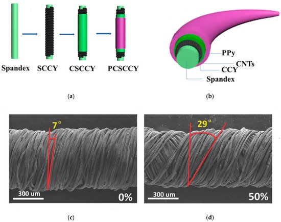
The working strain range of the one-dimensional sensor may be limited if the resistance is changed only by the cracks on the surface of the fiber or yarn. To improve its working strain range and stability, the structural adjustment of the yarns has also been explored. Cai et al. prepared a cotton/CNT core-spun yarn sensor by coating CNTs and depositing PPy on the surface (Figure 8a,b) [95]. The yarn has a broad strain range, up to 350%, but its GF is small, only 5.11 and 3.41 at strains of 0–50% and 50–350%, respectively. Cheng et al. developed a simple and mass-produced graphene-based composite yarn with a compression spring structure by plasma treatment and dipping (Figure 8c,d) [96]. The minimum and maximum detection limits of this double-wrapped composite yarn are 0.2 and 100% strain, respectively. Additionally, the signal response speed is fast (<100 ms). After several stretching cycles under 30 and 50% strain, the performance is stable, but its sensitivity is very low. Zhu et al. introduced curcumin-assisted chemical deposition (ELD) to prepare a helical yarn with a metal coating, and established a model to analyze its sensing mechanism [46]. The relative resistance change of the yarn ΔR¯¯¯ can be expressed as a function related to the tensile strain ε, including θ(ε), g(ε) and Rdetach(ε) (θ is the winding angle, g is the average gap of the separated winding, Rdetach is the resistance of an independent winding). As mentioned above, the yarn strain sensors based on geometric change sensing have excellent linearity, low hysteresis, high stability and a large sensing range, but their sensitivity is limited [15].
Figure 8. (
a) Schematic diagram of rubber thread and different core-spun yarns (
b) Cross-sectional structure of the PCSCCY yarn
[95] (
c) SEM image of PDCY-RGO under 0% strain, 7° (
d) SEM image of PDCY-RGO under 50% strain, with the winding angle marked as 29°
[96].
3.3.2. Braided Structure
Another design is to use braided yarns to fabricate yarn-based strain sensors. Shi et al. reported a sensor (BWY-AgNWs) composed of stretchable yarns with a braided structure and silver nanowires by dip coating (
Figure 9)
[97]. The fiber sensor can not only detect various deformations such as stretching, torsion, and bending, but also has a high stable sensitivity (GF = 65) in a larger sensing range (strain can reach 100%). However, due to the insufficient recovery of the microstructure and the brittleness of the AgNWs film, the microcracks cannot be completely merged after release, resulting in the poor repeatability of the strain sensor during multiple cycles of stretching. Furthermore, the high hysteresis of the strain sensor makes its strain response slow, which limits its wearable application. Yang et al. proposed a PET/AgNW/PDMS yarn sensor with braid yarns as the substrate, AgNW as the active material and PDMS as the protective layer by dip coating
[
| Dip coating |
| Braided yarn |
| Rubber/PET |
CNT |
44N; 350% |
0.12 kΩ/cm |
44% |
980 (29–44%) |
1000 (20%) |
N/A |
200 ms |
[ | 35 | ] |
| Spraying |
Helical coil |
PU |
CNT |
50.2 MPa; 1700% |
N/A |
900% |
N/A |
100 (200%) |
N/A |
N/A |
[99] |
| Spraying |
Helical layer |
TPU |
SWCNT/RGO |
40.0 MPa; 1237% |
821.8 S/m |
620% |
2160.4 (550–620%) |
1000 (50%) |
N/A |
N/A |
[100] |
4. Interconnection and Packaging
For wearable electronic applications, strain-sensing fibers or yarns need to be interconnected with other structural circuit elements or data acquisition circuits to fully integrate electronic devices. In wearable electronic devices, it is required that the sensing element must be firmly, elastically and electrically connected to the conductive wire or the data connector, and the interconnection point can still maintain high conductivity under considerable mechanical stress. In addition, the interconnection needs to robustly transmit the signal to the transmission board or processing electronics with minimal loss. At present, the common bonding methods in interconnection are mechanical bonding, physical bonding and chemical bonding
[101][102][101,102]. However, the chemical bonding is not suitable for the interconnection of heterogeneous devices. Mechanical bonding refers to the use of friction to clamp or connect electronic components to wires, which is suitable for electronic connections of various conductive textiles. For fiber or yarn strain sensors, the mechanical bonding can be thread-to-thread knotting, or embroidery
[103][104][103,104], stitching
[72], or interlacing. Physical bonding includes soldering
[105], adhesive bonding
[96] and so on. The advantages and disadvantages of different interconnection methods are summarized in
Table 7. Soldering is a process that the metal is melted with the high temperature to tightly coat and wrap electronic components to form a connection. However, few common fibers and yarns with conductive materials can withstand high temperature welding, and the narrow interface between the components is too small and difficult to handle. It is a method widely used in laboratories to connect strain-sensing yarns and functional components with conductive adhesives such as conductive glue and copper tape. For example, He et al. stitched MWCNT/TPU fibers onto an elastic bandage with cotton yarns to detect the wrist bending (
Figure 11a)
[72]. Both ends of the fibers were connected with conductive wires using silver paste and fixed by conductive tapes and medical tapes. Cheng et al. used conductive copper tape and silver paste to interconnect the two ends of graphene-based fibers as external electrodes with copper wires (diameter: 2 μm) (
Figure 11b)
[96]. Although this method is simple to operate, the electrical connection quality of the conductive adhesive is affected by humidity and temperature, and the copper tape is easily oxidized and has poor mechanical fatigue resistance, which may cause safety problems. Therefore, this type of interconnection often requires further suitable packaging protection.
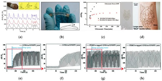
Figure 11. (a) MWCNT/TPU fiber sensors on an elastic bandage [72]. (b) The use of copper tape and silver paste to form the interconnections [96]. (c) ΔR/R0 of the sensor with 50 wt% RGO as a function of ultrasonic time [106]. (d) Photograph showing a large textile tattoo of a wolf on skin [107]. (e,f) Resistance–time relationships of the GNS/Au/GNS/PU yarn strain sensor (g,h) Resistance–time relationships of the PDMS-wrapped GNS/Au/GNS/PU yarn strain sensor with an applied strain of 50% under water spray [42].
Table 7.
Features of various interconnection methods.
| Method |
Merits |
Demerits |
| Soldering |
Tight connection and high conductivity. |
Brittle fracture, high welding temperature and limited welding interface. |
| Mechanical clamping机械夹紧 |
Flexible connection and wide range of application.连接灵活,应用范围广。 |
Easy to break under large deformation.在大变形下容易断裂。 |
| Conductive adhesive导电胶 |
Simple operation and less limitation to materials.操作简单,对材料的限制更少。 |
Easily affected by temperature and humidity.容易受到温度和湿度的影响。 |
Considering the stability and reliability of electrical interconnection and the durability of the strain sensor, the strain sensor is packaged for use. If strain sensors are integrated into clothing by textile technology, insulating coatings are considered to protect the sensors. For example, Li et al. used hydrophobic PDMS to pack the yarn-based strain sensor to achieve a good waterproof performance [42]. The relative resistance change values of the sensor without the hydrophobic packing increased significantly when the sensor was sprayed with water during the tensile cycle test (Figure 考虑到电气互连的稳定性和可靠性以及应变传感器的耐用性,对应变传感器进行了封装以供使用。如果应变传感器通过纺织技术集成到服装中,则考虑使用绝缘涂层来保护传感器。例如,Li等人使用疏水性PDMS来包装基于纱线的应变传感器,以实现良好的防水性能[42]。在拉伸循环试验期间,当传感器喷水时,没有疏水填料的传感器的相对电阻变化值显着增加(图11e,f). On the contrary, the relative resistance change values changed slightly before and after water (Figure ,f)。相反,相对电阻变化值在水之前和之后略有变化(图11g,h). Xu et al. reported the encapsulated TPU/SWCNT-RGO/PU core–sheath fiber [106]. The ΔR/R0 of the encapsulated composite fiber firstly increased by 10 and then remained stable, showing great washability compared with the SWCNT-RGO/PU sensor (Figure ,h)。Xu等人报道了封装的TPU/SWCNT-RGO/PU芯鞘纤维[106]。封装复合纤维的ΔR/R0首先增加了10,然后保持稳定,与SWCNT-RGO/PU传感器相比,显示出良好的耐洗性(图11c). Kwon et al. used self-healing polymers (T-SHPs) as self-adhesive and durable interconnection materials to encapsulate conductive sensing fibers. This method easily achieved the patterned design (Figure c)。Kwon等人使用自愈合聚合物(T-SHPs)作为自粘和耐用的互连材料来封装导电传感光纤。这种方法很容易实现图案化设计(图11d), but also effectively improved the conductivity of the sensing fiber over the 1000 stretch cycles [107]. Additionally, it is easy and convenient to fabricate, but not safe and reliable, only being suitable for laboratory tests. In addition, the strain sensor can be directly integrated into fabrics by the hot-melting process. The hot-melting package is made of elastic thermoplastic materials, such as TPU hot-melting adhesives. The materials are heated to the melting temperature and cooled after molding. For instance, Bahadir et al. reported a waterproof textile transmission line with GoreTexd),但也有效地提高了传感光纤在1000次拉伸循环中的导电性[107]。此外,制造起来简单方便,但不安全可靠,仅适用于实验室测试。此外,应变传感器可以通过热熔工艺直接集成到织物中。热熔包由弹性热塑性材料制成,例如TPU热熔胶。材料被加热到熔化温度,成型后冷却。例如,Bahadir等人报道了一种带有GoreTex防水焊接胶带的防水纺织品传输线,通过热空气密封[108]。从结构力学的角度来看,电子封装可以看作是由不同材料(基板-导电涂层-封装层)制成的复合结构,层之间的物理参数会影响平均应变传递速率和传感性能。此外,当设备承受热机械载荷时,这些材料之间的界面最容易发生故障。这是由于不同材料之间的界面键和两种材料的自由表面产生的固有应力集中。在反复的外部机械作用下,裂纹不仅限于界面,而且还平行地传播和扩展到界面[109]。因此,在高应变载荷下互连导线和应变传感器的系统集成仍然是一个巨大的挑战。接口不良不仅会导致严重的错误,还会导致整个传感器系统的可靠性低下。封装前后导电纱线的力学和传感性能会发生一定程度的变化。然而,目前对包装工艺对可伸缩导电纤维或纱线传感性能的影响缺乏全面的研究。® waterproof welding tape by hot air sealing [108]. From the perspective of structural mechanics, electronic packaging can be seen as a composite structure made of different materials (substrate-conductive coating-encapsulation layer), and the physical parameters between the layers will affect the average strain transfer rate and sensing performance. In addition, when the device is subjected to thermo-mechanical loads, the interface between these materials is the most prone to failure. This is due to the inherent stress concentration generated by the interface bonds between different materials and the free surface of the two materials. Under repeated external mechanical action, cracks are not limited to the interface, but also propagate and expand parallelly to the interface [109]. Therefore, the system integration of interconnected wires and strain sensors under high-level strain loads is still a huge challenge. Poor interfaces will not only cause serious errors, but also lead to low reliability of the entire sensor system. The mechanical and sensing properties of conductive yarns before and after encapsulation will change to a certain degree. However, there is currently a lack of comprehensive research on the effect of packaging process on the sensing performance of stretchable conductive fibers or yarns.