The focus of the entry is on the mechanism of vanadium-catalyzed reactions responsible for the amplification of the analytical signal of Ge(IV) is studied. The analytical efficacy of different catalytic systems is compared, and the optimal parameters of the respective procedures are reported.
- vanadium
- germanium
- aminopolycarboxylic complexes
- catalytic adsorptive stripping voltammetry
- HEDTA
1. Adsorptive Stripping Voltammetric Determination of Germanium
2. Catalytic Amplification of Germanium Voltammetric Signals in the Presence of Oxoacid Anions
| Ligand | Catalytic Agent | Supporting Electrolyte |
Electrode | P | 2 | /P | 1 | 1 | Linear Range nM | LOD nM | References | |
|---|---|---|---|---|---|---|---|---|---|---|---|---|
 | Benzene-1,2-diol catechol |
BrO | 3− | Acetate buffer | DME | 2.2 | 1–7000 | 1 | [15] | |||
| VO | 2+ | HClO | 4 | , NaClO | 4 | HMDE | 11 | n.a. | n.a. | [19] | ||
| BrO | 3− | Acetate buffer | HMDE | 24 | n.a. | n.a. | [20] | |||||
| V(IV)-EDTA | Acetate buffer | HMDE | 3.5 | n.a. | n.a. | [20] | ||||||
| V(IV)-HEDTA | Acetate buffer | HMDE | 26 | 0.05–20 | 0.01 | [20] | ||||||
| V(IV)-HEDTA | Acetate buffer | Hg(Ag)FE | n. a. | 0.01 | 0.15 | [20] | ||||||
| V(IV)-HEDTA | Acetate buffer | BiFE/GC | n. a. | 1.5–24 | 1.0 | [21] | ||||||
| V(IV)-HEDTA | Acetate buffer | BiFE/SPE | n. a. | 1.5–19.5 | 1.0 | [21] | ||||||
| V(IV)-HEDTA | Acetate buffer | BiFE/SPE | meso | n. a. | 5.0–70 | 1.2 | [21] | |||||
 | Benzene-1,2,3-triol Pyrogallol |
BrO | 3− | Acetate buffer, trisodium citrate |
BiFE/GC | 1.5 | 7–230 | 0.8 | [16] | |||
| V(IV)-HEDTA | Acetate buffer | HMDE | 100 | 0.25–25 | 0.02 | [22] | ||||||
| V(IV)-EDTA | Acetate buffer | HMDE | 10 | n.a. | n.a. | [22] | ||||||
| V(IV)-NTA | Acetate buffer | HMDE | 1.5 | n.a. | n.a. | [22] | ||||||
 | 3,4,5-Trihydroxybenzoic acid, gallic acid |
V(IV)-EDTA | HClO | 4 | HMDE | n.a. | 0.03–10 | 0.02 | [17] | |||
| V(IV)-EDTA | H | 2 | SO | 4 | DME | 10 | 0.55–275 | 0.05 | [18] | |||
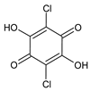 | 2,5-Dichloro-3,6-dihydroxycyclohexa-2,5-diene-1,4-dione, chloranilic acid |
V(IV)-HEDTA | Acetic acid | HMDE | 21 | 0.75–50 | 0.085 | [23] | ||||
| V(IV)-HEDTA | Acetic acid | Hg(Ag)FE | 12 | 1–25 | 0.7 | [23] | ||||||
 | 3,4-Dihydroxybenzaldehyde (DHB) |
V(IV)-EDTA | KCl | HMDE | 17 | 0.1–10 | 0.05 | [24] | ||||
|
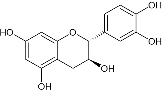
Catechin |
V(IV)-HEDTA | Acetate buffer | HMDE | n.a. | 40-480 | n.a. | [25] | |||||
|
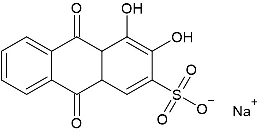
Alizarin sodium monosulfonate |
V(IV)-HEDTA | Acetate buffer | HMDE | n.a. | 40-440 | n.a. | [25] | |||||
|
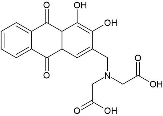
Alizarin complexone |
V(IV)-HEDTA | Acetate buffer | HMDE | n.a. | 40-1200 | n.a. | [25] |
3. Catalytic Amplification of Germanium Voltammetric Signals by Aminopolycarboxylic Acid Complexes with V(IV)
The Ge(IV) can be also efficiently amplified by complexes of V(IV) with aminopolycarboxylic acids such as EDTA, HEDTA and NTA. The ratio of the peak current obtained when the catalytic systems are used to the peak current obtained for the AdSV system in the absence of any oxidant ranges from several to several dozens. The amplification factor (PCAdSV/PAdSV) depends on many parameters, primarily on the type of V(IV) complex and the ligand that form complexes with Ge(IV), but also on the type of the working electrode, the supporting electrolyte composition, and, finally the instrumental parameters.
The characteristic features of the cyclic voltammograms obtained for the catalytic systems of Ge(IV) employing aminopolycarboxylic acid complexes of V(IV) are highlighted in Figure 1.
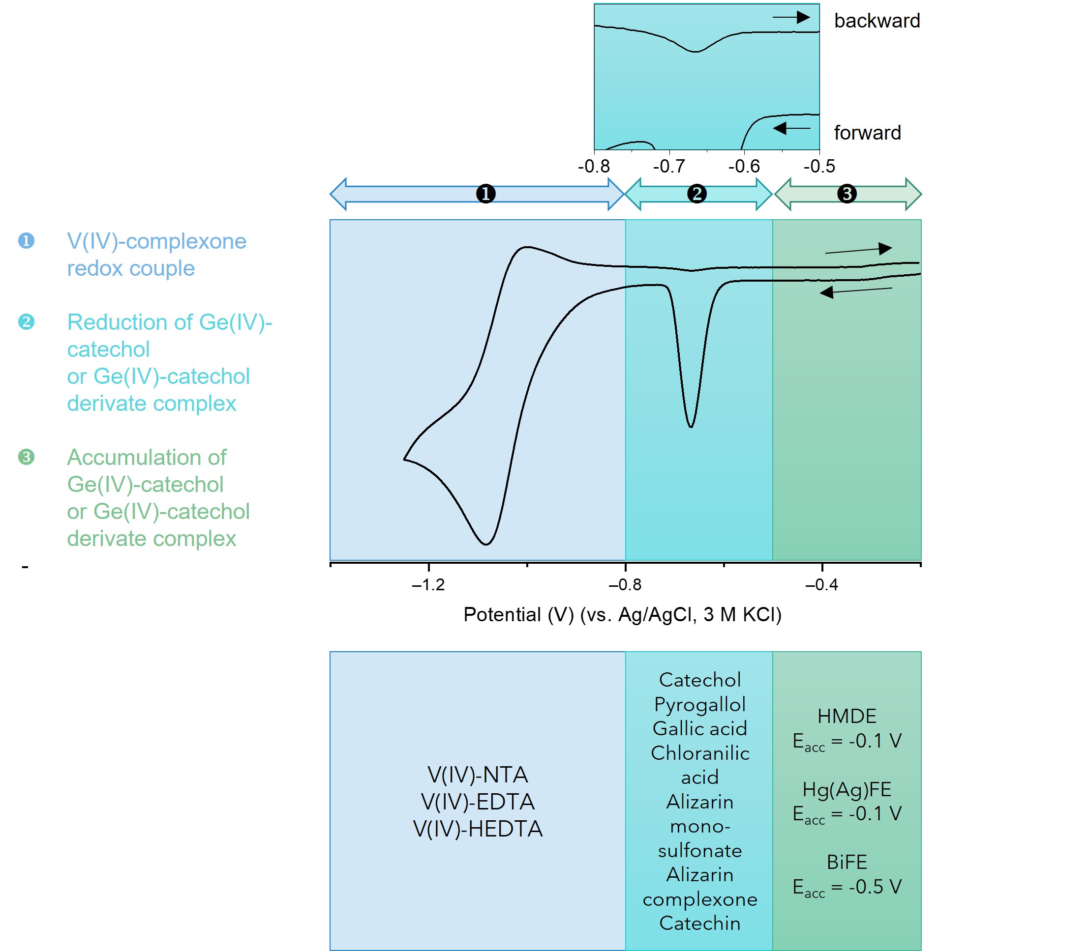
Figure 1. CV voltammogram of the Ge(IV) catalytic system and its characteristic features.
Part 1 of the CV voltammogram represents the region of the reduction-oxidation of the V(IV) complex. A vanadium complex that undergoes a more electrochemically reversible reduction can amplify the germanium signal to a greater extent than one that is reduced irreversibly. The catalytic activity of the three reported ligands can be ranked as follows: HEDTA > EDTA > NTA. The region labeled 2 represents the catalytically amplified signal of germanium. The peak potential of the Ge(IV) signal depends on the ligand type and the material of the working electrode. It is localized between -0.55 V and -0.65 V for the HMDE and Hg(Ag)FE electrodes. When BiFE electrodes are used, the Ge(IV) peak appears at slightly more negative potentials namely, between -0.7 V and -0.8 V. Additionally, both the negative-going and positive-going branches of CV runs show cathodic signals, which confirms the catalytic nature of the electrode process. The cathodic peak observed at backward running is clearly visible on the magnified part of section 2. Such a CV curve implies that the investigated catalytic systems may be attributed to catalytic systems of the second kind
Part 1 of the CV voltammogram represents the region of the reduction-oxidation of the V(IV) complex. A vanadium complex that undergoes a more electrochemically reversible reduction can amplify the germanium signal to a greater extent than one that is reduced irreversibly. The catalytic activity of the three reported ligands can be ranked as follows: HEDTA > EDTA > NTA. The region labeled 2 represents the catalytically amplified signal of germanium. The peak potential of the Ge(IV) signal depends on the ligand type and the material of the working electrode. It is localized between -0.55 V and -0.65 V for the HMDE and Hg(Ag)FE electrodes. When BiFE electrodes are used, the Ge(IV) peak appears at slightly more negative potentials namely, between -0.7 V and -0.8 V. Additionally, both the negative-going and positive-going branches of CV runs show cathodic signals, which confirms the catalytic nature of the electrode process. The cathodic peak observed at backward running is clearly visible on the magnified part of section 2. Such a CV curve implies that the investigated catalytic systems may be attributed to catalytic systems of the second kind [26]. Under this assumption, the electroreduction of adsorbed Ge(IV)-catechol produces a very active Ge(II)-catechol complex [GeII(OH)2L2]4- (Scheme 1), which forms a composite complex with V(IV)-HEDTA denoted as [GeII(OH)2L2]-[VIVO(HY)] (Scheme 1). In this composite complex, vanadium(IV) undergoes reduction to vanadium(II), which results in the breakdown of the multi-component complex. The regenerated germanium catecholate complex [GeII(OH)2L2]4-retains its activity and combines with additional V(IV)-HEDTA ion. In this way, the catalytic cycle forms, indicated by an arrow in Scheme 1. The number of electrons per germanium ion exchanged during electroreduction increases significantly, which contributes to a substantial rise in the current of the recorded germanium peaks, and thus to an increase in the sensitivity of the analytical procedure.
 Scheme 1. Catalytic reactions responsible for the amplification of the Ge(IV) voltammetric signal.
The section labeled 3 presents the range of potentials that can be applied for the adsorptive accumulation of the Ge(IV) complex. On the positive side of potentials, this range is limited by the oxidation process of the electrode material. In the case of the bismuth electrode, this range is narrower than that for the mercury electrode, because the bismuth oxidation process is already noticeable at potentials more positive than -0.4 V.
To apply the catalytic system for the determination of Ge(IV), an extensive optimization study should be undertaken on the influence of chemical and instrumental variables.
References
- Gleb S. Pokrovski; François Martin; Jean-Louis Hazemann; Jacques Schott; An X-ray absorption fine structure spectroscopy study of germanium-organic ligand complexes in aqueous solution. Chemical Geology 2000, 163, 151-165, 10.1016/s0009-2541(99)00102-3.
- Schleich C., Henze, C.; Trace analysis of germanium. Part 2. Polarographic behaviour and determination by adsorptive stripping voltammetry. Fresenius' Journal of Analytical Chemistry 1990, 163, 145.
- Robert Piech; Study on simultaneous measurements of trace gallium(III) and germanium(IV) by adsorptive stripping voltammetry using mercury film electrode. Journal of Applied Electrochemistry 2010, 41, 207-214, 10.1007/s10800-010-0225-4.
- Suw Young Ly; Sang Su Song; Sung Kuk Kim; Young Sam Jung; Chang Hyun Lee; Determination of Ge(IV) in rice in a mercury-coated glassy carbon electrode in the presence of catechol. Food Chemistry 2006, 95, 337-343, 10.1016/j.foodchem.2005.02.029.
- Alvarez, J.M., Calzon, J.G., Fonseca, J.L.; Electrochemical Reduction of Ge(IV) Catalyzed by o-Catechol at the Dropping Mercury Electrode and at the Hanging Mercury Drop Electrode after Adsorptive Preconcentration. Electroanalysis 1999, 11, 656.
- J L Muñiz Alvarez; J A García Calzón; J M López Fonseca; Square-wave voltammetry of the o-catechol-Ge(IV) catalytic system after adsorptive preconcentration at a hanging mercury drop electrode.. Talanta 2001, 53, 181.
- Kiyoshi Hasebe; Satoshi Hikima; Teiji Kakizaki; Tsuyoushi Iwashimizu; Koichi Aoki; Trace determination of germanium by means of adsorption waves in differential-pulse polarography. The Analyst 1990, 115, 413-416, 10.1039/an9901500413.
- Changqing Sun; Qian Gao; Liling Liu; Adsorptive stripping measurements of germanium(IV) in the presence of pyrogallol. Talanta 1995, 42, 881-884, 10.1016/0039-9140(95)01501-2.
- Julio César Aguilar; Josefina De Gyves; Determination of germanium(IV) in sulphide ores by differential pulse polarography in pyrogallol-sulfuric acid media. Analytica Chimica Acta 1995, 306, 243-247, 10.1016/0003-2670(95)00013-p.
- Gökmeşe, F., Gökmeşe, E., Osman Solak, A.; A new adsorptive square-wave stripping voltammetric method for the trace analysis of germanium. Hacettepe Journal of Biology and Chemistry 2008, 36, 215-221.
- Alan M. Bond; Steven Kratsis; O. Michael G. Newman; Adsorptive Stripping Voltammetric Determination of Germanium in Zinc Plant Electrolyte. Electroanalysis 1998, 10, 387-392, 10.1002/(SICI)1521-4109(199805)10:6%3c387::AID-ELAN387%3e3.0.CO;2-W.
- Malgorzata Grabarczyk; Optimization of Adsorptive Stripping Voltammetry Procedure Using Chloranilic Acid as a Complexing Agent for the Determination of Ultra-Trace Germanium in Natural Water Samples. Journal of The Electrochemical Society 2017, 164, H872-H876, 10.1149/2.0841713jes.
- Malgorzata Grabarczyk; Marzena Adamczyk; Bismuth film electrode and chloranilic acid as a new alternative for simple, fast and sensitive Ge(iv) quantification by adsorptive stripping voltammetry. RSC Advances 2018, 8, 15215-15221, 10.1039/c8ra01160e.
- R. G. Canham; D. A. Aikens; Nicholas Winograd; Glenn Mazepa; Mechanism of polarographic reduction of germanium(IV) in acidic catechol medium. The Journal of Physical Chemistry 1970, 74, 1082-1087, 10.1021/j100700a020.
- Shi Jinhui; Jiao Kui; Adsorptive complex catalytic polarographic determination of germanium in soils and vegetables. Analytica Chimica Acta 1995, 309, 103-109, 10.1016/0003-2670(95)00027-w.
- Shangwei Zhong; Jiali Su; Liang Chen; Jiefeng Tong; Wenfang Jia; Xiangjun Li; Hong Zou; Determination of Total Germanium in Chinese Herbal Remedies by Square-Wave Catalytic Adsorptive Cathodic Stripping Voltammetry at an Improved Bismuth Film Electrode. International Journal of Electrochemistry 2013, 2013, 1-7, 10.1155/2013/735019.
- Yi-Heng Li; Xin-Huan Chen; Mei-Hua Huang; Fang-Qin Zhou; Catalytic Adsorptive Stripping Voltammetry of Germanium(IV) in the Presence of Gallic Acid and Vanadium(IV)-EDTA. Electroanalysis 2007, 19, 704-708, 10.1002/elan.200603803.
- YueXia Zhang; Yongming Wu; Enhancement Mechanism of the Oscillopolarographic Current of Germanium(IV)-Trihydroxybenzoic Acid System and Application.. Analytical Sciences 1997, 13, 279-284, 10.2116/analsci.13.supplement_279.
- Jesús L. Muñiz Álvarez; Josefa A. García Calzón; Juan M. López Fonseca; Coupling of Ligand-Catalyzed Electroreduction of Metal Ions with Redox Electrocatalysis. Application of the o-Catechol-Ge(IV)-V(IV) Double Catalytic System for the Sensitive Determination of o-Catechol. Electroanalysis 2001, 13, 181-185, 10.1002/1521-4109(200103)13:3<181::aid-elan181>3.3.co;2-6.
- Jerzy Zarębski; Andrzej Bobrowski; Julia Gonciarczyk; Agnieszka Królicka; Extremely sensitive germanium stripping voltammetric determination with the use of a new Ge(IV)-catechol-V(IV)-HEDTA catalytic adsorptive system. Electrochimica Acta 2019, 324, 134859, 10.1016/j.electacta.2019.134859.
- Agnieszka Królicka; Jerzy Zarębski; Andrzej Bobrowski; Catalytic Adsorptive Stripping Voltammetric Determination of Germanium Employing the Oxidizing Properties of V(IV)-HEDTA Complex and Bismuth-Modified Carbon-Based Electrodes. Membranes 2021, 11, 524, 10.3390/membranes11070524.
- Jerzy Zarębski; Andrzej Bobrowski; Julia Gonciarczyk; Agnieszka Królicka; Selection of Optimal Ligand and Vanadium(IV) Complexonate for Sensitive Catalytic Adsorptive Stripping Voltammetric Quantification of Germanium. Electroanalysis 2020, 32, 2213–2219, 10.1002/elan.202060055.
- Jerzy Zarębski; Andrzej Bobrowski; Agnieszka Królicka; Julia Gonciarczyk; Vasiliki Manolopoulou; Anastasios Economou; A novel catalytic adsorptive stripping voltammetric method for the determination of germanium ultratraces in the presence of chloranilic acid and the V(IV)·HEDTA complex. Journal of Solid State Electrochemistry 2020, 24, 1-9, 10.1007/s10008-020-04669-0.
- Changqing Sun; Qian Gao; Jiubai Xi; Hongding Xu; Determination of germanium(IV) by catalytic cathodic stripping voltammetry. Analytica Chimica Acta 1995, 309, 89-93, 10.1016/0003-2670(95)00019-v.
- Agnieszka Królicka; Jerzy Zarębski; Andrzej Bobrowski; Application of Aminopolycarboxylic Complexes of V(IV) in Catalytic Adsorptive Stripping Voltammetry of Germanium. Chemosensors 2022, 10, 36, 10.3390/chemosensors10010036.
- Bobrowski Andrzej, Zarebski Jerzy; Catalytic Adsorptive Stripping Voltammetry. Electroanalysis 2000, 12, 1177, 10.1002/1521-4109(200010)12:153.0.CO;2-U.

