Overcurrent relays (OCR) are used as the main protection device due to their lower cost compared to other types of relays. Overcurrent relays can be divided roughly into two types, judging by their time–current characteristic: definite-time OCRs and inverse-time OCRs.
1. Introduction and Theoretical Background
Due to the accelerated expansion of the distribution electric power grid caused by increased consumer demand and the need for increasingly reliable service that complies with regulatory requirements, strong and robust protection of the distribution electric power system is necessary. Investment in protection technologies and devices is very important in order to achieve a certain level of reliability and quality of the electrical power supply. Different power system configurations with their own protection coordination philosophies have unique advantages and disadvantages
[1], which means that each part of the distribution power system must be properly protected to avoid a power outage and its consequences regarding equipment malfunction and failure
[2].
Protective relays are the most important means to meet the aforementioned requirements
[3]. The purpose of the protective relay is to de-energize the faulted part of the distribution power system and prevent the rest of the system from being affected in the event of an abnormal condition or fault, such as a short circuit
[4]. To prevent the aforementioned events and their influence on consumers, the relays are set in coordination with each other. Properly coordinated relays are very important for the power distribution system because poor coordination can have serious consequences on the power system, such as power outages, damage to the equipment and utility station malfunctions.
Protection coordination requires the selection of the protection devices’ settings so that the device responds properly in case of an emergency. Short circuit and load flow analysis are required to obtain correct inputs for relay protection coordination
[5]. The coordination schemes must ensure reliability, selectivity, sensitivity and speed of protection relays.
In distribution systems, one of the basic power system protection strategies is overcurrent protection (I>). Overcurrent relays (OCR) are used as the main protection device due to their lower cost compared to other types of relays
[6]. On the other hand, in transmission power networks OCRs are used only as backup protection, while distance relays are used as a primary protection of transmission lines. This was done due to their relatively high time delays (the problem of OCR selectivity). However, distance relays are usually not used in distribution networks because they represent a significantly much costlier solution compared to using standard OCRs
[7]. Therefore, OCR coordination in a power distribution network is an important concern for a protection engineer. It must be noted that in active networks (with distributed generation units) OCRs are used in junction with under/over voltage protection devices, under/over frequency protection devices, and other devices. Usually, numerical relays have all those protection functions integrated in a single device.
When a fault occurs in the power system, the current magnitude increases
[8]. The overcurrent relays measure the fault current and compare it with the predefined threshold values. When the current level rises above the threshold, a trip command is issued after a predefined time delay, and the corresponding circuit breaker opens its contacts and isolates the faulted area.
2. Types of OCRs and Their Usage
Overcurrent relays can be divided roughly into two types, judging by their time–current characteristic: definite-time OCRs and inverse-time OCRs
[9][10][9,10]. Definite-time OCRs have a relatively simple time–current characteristic, in which time is not a function of current magnitude. In other words, when the current overshoots its threshold value, the relay will detect this value (via current measurement transformers, CTs) and react either instantaneously or after a predetermined time delay Δt. Inverse-time OCRs have an inverse time–current characteristic, in which time is a function of current magnitude, so depending on current value measured by CTs, relays will react slower (lower short-circuit currents) or faster (higher short-circuit currents). Numerical relays can combine the aforementioned types of relays in a single relay that has a joint inverse- and definite-time characteristic. Usually, inverse-time characteristic is reserved for lower currents and definite-time characteristic (with an instantaneous trip function) is reserved for higher currents. This is similar to the operation of a Molded Case Circuit Breaker (MCCB), used in low-voltage networks, where the bimetallic strip is associated with an inverse-time characteristic and the electromagnetic solenoid (or coil) is associated with a definite-time characteristic (usually instantaneous trip).
Depending on the circumstances, either definite-time OCRs or inverse-time OCRs can be used in medium voltage distribution networks, or even both
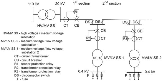
[11][12][11,12]. Definite-time OCRs are usually used for protection of lines that are not characterized with high inrush currents and whose impedance does not change very much with their length. The latter is indicated for relatively short networks that contain lines with larger cross-sections. On the other side, inverse-time OCRs are usually used for protection of elements with high start-up currents (asynchronous motors) or magnetizing currents (transformers) and lines whose impedance changes significantly with their length (relatively long networks). The use of both relay types is displayed in
Figure 1, where a feeding substation is delivering power to the distribution network consumers.
Figure 1.
Combined use of definite-time and inverse-time overcurrent relays (OCRs).
Consumers can be connected on a low voltage (LV) network or directly on a medium voltage (MV) network, meaning that in the latter case the MV/LV transformer and the downstream network is a customer’s ownership and maintenance responsibility. However, in both cases the protection philosophy is similar: the feeder’s first line section contains the protection elements (relay denoted as R1 and circuit breaker), which cover all subsequent lines of that feeder. This means that if the short circuit (of any type) occurs, for example on the last line of the feeder, the CT located in the beginning of the first section must detect it and send the information to the relay, which will then initiate the opening of the CB contacts, thereby de-energizing the entire feeder. This situation is actually critical in overcurrent relay protection settings, because it requires that relay R1 must detect the lowest short-circuit current, which is usually associated with 2-phase fault occurring on the end of the feeder. A 2-phase short circuit is lower in magnitude than a 3-phase short-circuit current
[13], according to the well-known relation
ISC2=0.86⋅
ISC3. It must be noted that for this relation to be true, inverse network impedance must equal direct impedance, which is usually the case in passive distribution networks. In addition, it is important to note that single phase fault (associated with low or high ohmic earthing of the feeding HV/MV substation) or earth fault (associated with isolated operation of the feeding HV/MV substation) will not be considered here. The reason is that I
0> protection coordination has a much different philosophy than the multiphase protection due to the specific physical conditions occurring in earth (or single phase) faults, which include zero currents and impedances.
It must also be emphasized that
Figure 1 represents the topology and protection philosophy of a typical European medium voltage distribution network. However, in later references and reviewed papers, authors use topologies and protection philosophies that differ from European practice and in which relays are placed on all MV lines (usually from both sides in tandem with directional overcurrent relays), and the authors’ goal will be to bridge the gap between theoretical and practical observations.
Returning to
Figure 1, it is interesting to point out that the MV feeder cubicle of MV switchboard actually contains CT, relay and CB mechanism, so the term beginning of the feeder is synonymous with the feeder MV cubicle. The feeder relay is usually a definite type OCR, which also contains the instantaneous trip function (I>>). However, the relay protecting the MV/LV transformer is usually an inverse-time OCR, due to the large (5–10 times) magnetizing current flowing through its primary winding when energized without load. The idea is to set the relay to allow the temporary flow of the increased magnetizing current until it subsides, since this is a normal transient operation of the transformer and not a faulty state. Otherwise, unnecessary trips would render the transformer unusable. This applies to all MV/LV power transformers in the network (R2, R3, etc.). Of course, transformers and feeder protection must be selective, that is, in case the fault occurs on LV busbars or the transformer itself, the associate transformer relay must trip first. Only in case of its CT, relay or CB malfunction, the feeder relay must react after a time delay, thereby de-energizing the whole feeder (including all MV/LV transformers).
The above discussion was illustrative of the MV network with radial topology and radial operation. Radial operation is almost universal for MV (and LV) networks. However, MV networks in urban areas can have a loop (or ring) topology, meaning that two (or more) MV feeders from the same HV/MV substation are physically connected with a line that operates in open-circuit mode (on one end the line is opened via switch-disconnector in the MV switchboard of a MV/LV substation). In addition, MV networks in densely populated urban areas can have an interconnected topology, meaning that two (or more) MV feeders from two (or more) separate HV/MV substations are physically connected with a line that operates in open-circuit mode. In this way the security of supply is even greater than in loop topology, since it allows the malfunction of an entire HV/MV substation without affecting electric power delivery to associated loads, because now they can be fed from the remaining HV/MV substation by means of network switching (reconfiguration). Both topologies (loop and interconnected) can change their configuration (and operation) by simply changing the position of normally open-point (NOP), which is of course the switch-disconnector. In practice that means opening the switch-disconnector in an MV switchboard of another MV/LV substation and closing the one that was previously opened. Still, the same protection rules apply for both topologies with one important distinction: the definite-time OCRs are used in networks where the impedance of the network changes very little with the position of normally open-point (NOP), while inverse-time OCRs are used in networks where the impedance of the network changes greatly with the position of normally open-point (NOP).
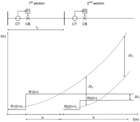
Generally speaking, it can be said that inverse-time OCRs cover the major part of the primary protection zone more efficiently than definite-time OCRs, since they have a faster time response, but it is the opposite for the rest of primary protection zone and a back-up (reserve) protection zone. Both are displayed in
Figure 2, where inverse-time OCR characteristic is displayed with a dotted line and definite-time OCR characteristic is displayed with a continuous line. In area “a” of the relay R1 inverse time beats definite time (it reacts faster), but in area “b” it is the opposite. The same applies for relay R2. It must be noted that area “a” does not have to correspond to the total length of the relay R1 primary protection zone, but in most cases it encompasses its major part.
Figure 2.
Definite-time OCRs vs. inverse-time OCRs.
Additionally, time delay Δt between two relays is uniform and usually lower for two consecutive definite-time OCRs compared to inverse-time OCRs, as is displayed in
Figure 2. This is because in most cases it is much easier to set and maintain a predetermined Δt on a network where definite-time OCRs are used (Δt
1) instead of a network where inverse-time OCRs are used (Δt
2 and Δt
3). The reason for this is that in the latter case operation time is a function of current magnitude, and a protection engineer cannot set the same (uniform) time delay Δt for the entire back-up protection zone. In fact, due to the nature of the inverse function, time delay between two consecutive relays increases with the length of back-up protection zone (Δt
2 < Δt
3). However, when using definite-time OCRs everything involving time delay determination is much simpler. It is very important to note that the time delay Δt between two consecutive relays used here is not yet explained in detail. In fact, Δt is an important factor in determining miscoordination between primary and backup relay(s).