Your browser does not fully support modern features. Please upgrade for a smoother experience.
Please note this is a comparison between Version 2 by Jason Zhu and Version 1 by Vladimir Sousa Santos.
Microgrids have been proposed as a solution to the growing deterioration of traditional electrical power systems and the energy transition towards renewable sources. During the design of an microgrid (MG), the components and physical arrangement must be considered to achieve a proper transition between the different modes of operation. The connection of the loads, the microgenerators, and the storage elements, require rigorous analysis to obtain the operation and the desired efficiency by the network operator and the user. The way to interconnect all the elements of the network is known as MG topology.
- distributed generation
- electrical power system microgrid
- network topology
1. Introduction
During the design of an microgrid (MG), the components and physical arrangement must be considered to achieve a proper transition between the different modes of operation. The connection of the loads, the microgenerators, and the storage elements, require rigorous analysis to obtain the operation and the desired efficiency by the network operator and the user. The way to interconnect all the elements of the network is known as MG topology [39,40].
-
Control mechanisms of the dynamic characteristics of the distributed generation (DG) resources;
-
Voltage regulation and frequency for power balance both in island mode and connected to the EPS;
-
The transition between operation modes to detect situations that cause changes;
-
Economic dispatch to share the load between different DGs;
-
Renewable sources are available;
-
Minimum impact on the distribution network;
-
Coordination between DERs.
Depending on the type of power supplied, microgrid (MG) topologies are divided into DC, AC, hybrid, and 3-NET [21,43,44][4][5][6]. According to its configuration, MGs are classified into cascade-type and parallel-type MGs.
AC MG systems use the same operating mechanisms as traditional AC power systems, such as frequency, voltage levels, and protection features [45][7]. DC MGs have been implemented in recent times because of the development of power electronics technology that has increased DC loads and power converters for DC voltage transformation at different levels for different applications [46][8]. At present, DC MG systems are implemented in special applications such as aviation, automotive, marine, and manufacturing industries; however, an expansion in residential distribution systems is planned [47,48][9][10].
In the coupled AC topology, the connection to the EPS is made through an AC MG. In the decoupled AC topology, there is not a direct connection between the utility EPS and the AC MG [2][11]; therefore, it is more expensive. A decoupled MG, in general, is more expensive than coupled MG because higher capacity AC-DC converters are needed [2,49,50][11][12][13]. The multiple MGs’ topology corresponds to a network of several MGs AC or DC that are connected to the high-voltage network and other MGs.
The 3-Net MG topology consists of the union of three different types of networks: a high-quality DC network, a low-quality DC network, and an AC network. This topology makes it possible to supply energy in a single MG to elements of different levels of sensitivity concerning changes in the power quality parameters. An example is rural networks that may have loads such as computers, which are very sensitive to voltage disturbances, along with loads such as water heaters, which are not sensitive to these disturbances. Although 3-Net MGs have high reliability, they represent a higher cost in their development and implementation [39][14].
According to the configuration, MG topologies can be divided into two categories: parallel type and cascade type. The parallel type has been the subject of numerous investigations and is used in applications that include state-of-charge (SOC) balance for storage systems and obtaining optimal economic distribution schemes for DGs [43][5]. They also include voltage drop control with a maximum power point tracking (MPPT) regulator of PV systems and an optimal DG distribution scheme.
The cascade type is recent and has a relevant function in applications that require the reliable use of DER at a high-voltage level [51][15]. Furthermore, it is practical in MGs that operate in island mode, where the energy balance between all modules is fundamental [51,52,53][15][16][17].
2. Control Structures of DC and AC MGs
According to the control structures, the AC and DC MGs are divided into two groups as can be seen in Figure 1. The first group is the control methods, and the second group is the load-sharing techniques [54,55][18][19].
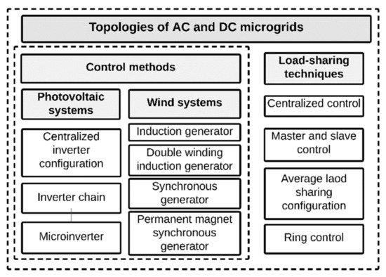
In the control structures, the power electronic converters are essential components because they must ensure the adequate supply and distribution of the electrical load without affecting the correct operation of the system [55,56][19][21].
2.1. Control Method
PV Systems
In PV systems the control methods depend on the type of configuration (i.e., centralized inverter, inverter chain, and microinverter configuration).
Centralized Inverter Configuration
The centralized inverter configuration, has one of the highest efficiencies of all PV systems (over 98%). This configuration is estimated to be used in 44% of PV systems installed in the commercial and utility sectors.
This configuration is used mainly in residential as well as in small and medium commercial applications offering reliability [57,58,59][22][23][24]. Additionally, both the implementation and maintenance costs are the lowest of the PV configuration types [57,58,59][22][23][24]. However, damage to the inverter stops the entire system, so constant maintenance is necessary, and available inverters are required for replacement [57,58,59][22][23][24]. Some applications using this topology for AC and DC MGs were assessed in [60,61,62][25][26][27].
Inverter Chain Configuration
The inverter chain represented in Figure 2 has high efficiency (approx. 98%), making it highly profitable. It has power ranges of around 150 kW peak and is estimated to have the highest percentage of use in the market [57,58,59][22][23][24].
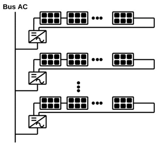
This configuration is reliable, which allows it to be used in residential and some commercial applications. Because there are different inverter cell groupings, the damage of one does not prevent the system from generating power continually [57,58,59][22][23][24]. However, this configuration is expensive because it requires an inverter for each group of cells, increasing maintenance costs [57,58,59][22][23][24]. Applications with this configuration were studied in [63,64,65][28][29][30].
Microinverter Configuration
The microinverter configuration, presented in Figure 3, is the least used. In this configuration, the inverter is connected directly to a battery and converts DC to AC.
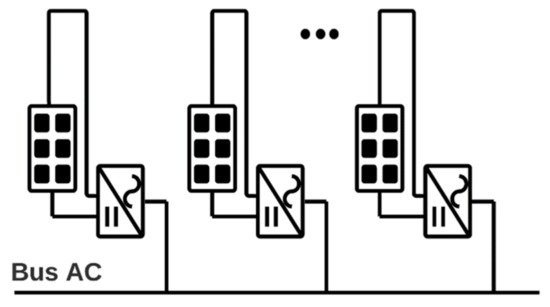
The batteries are charged by PV cells and are optimized to be used with a single PV panel [57,58,59][22][23][24]. In this configuration, installation costs are low, and parts are easy to replace, ensuring continuous use and fast maintenance. In addition, the panels are independent, which means that the failure of one does not affect the total system [57,58,59][22][23][24]. However, it does not have galvanic isolation between the AC-DC connection, affecting reliability between users [57,58,59][22][23][24]. In [66,67][31][32] various implementations of this architecture were assessed.
Wind Systems
In wind systems, the control methods depend on the technology of the generator used (i.e., induction generator, double-winding induction generator, synchronous generator, and permanent-magnet synchronous generator).
Induction Generator
The induction generator configuration can be divided into cage rotor and wound rotor. In addition, it can present multiple configurations according to the use of the loads, such as capacitor banks, frequency converters, and starters. This configuration generates electricity, converting the mechanical energy of the movement of the blades into a magnetic field [31,58][33][23].
This configuration is built robustly, ensuring its prolonged use. Generally, it does not require additional elements and can easily be used in parallel configurations in spaces already used, such as farms and vacant lots [31,58][33][23]. However, this configuration has moving parts that require constant maintenance, take up a lot of space, and generally require high starting torque. Additionally, the power factor of this generator can be reduced to low values [31,58][33][23]. This topology was used in [68,69][34][35].
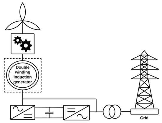
Double-Winding Induction Generator
Synchronous Generator
This configuration, as shown in Figure 5, comprises a fixed stator with a three-phase wound and a rotor with a magnetic field. They also have multiple subdivisions based on construction, excitation mode, and the parts used [70][36].
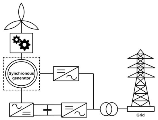
The synchronous generator has a wide range of configurations, making it suitable for multiple situations and locations. An example is the excitation mode, which can be used as power from the EPS or through a capacitor bank. In [70][36], a comparative study was performed of each type of synchronous generator according to its subdivisions. The disadvantage of this configuration depends on the selected construction. For example, if a variable speed induction generator with a partial power converter is chosen, an energy loss is produced due to the heat in its gears. In [70][36], an analysis was performed according to its subdivision.
Permanent-Magnet Synchronous Generator
Figure 6 shows the permanent-magnet synchronous generator configuration.
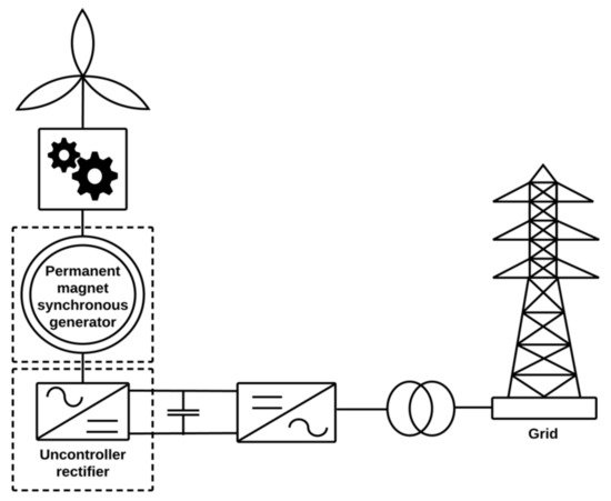
This configuration is generally used in offshore wind turbines [71][37]. Its operating principle is like the synchronous generators, in terms of the dependence of the speed on the energy consumption of the EPS. Due to their construction characteristics, they generate a large amount of power [72,73][38][39]. However, its use is limited because it has more complex control systems and a high maintenance cost [72,73][38][39].
2.2. Load Sharing Techniques
Load sharing techniques are divided according to the type of control (i.e., centralized control, master and slave control, average load sharing control, and ring control).
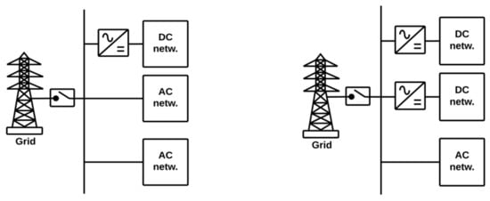
Centralized control
In centralized control, the loads and DG units connect via a centralized connection or centralized DC bus. In this configuration presented in Figure 7, the main or centralized control has two functions: to link the MG with the user or with the EPS [74,75][40][41].
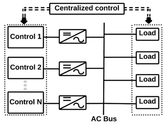
This configuration presents high efficiency at low costs and only requires a converter for connection to the EPS. Additionally, the electronic elements used are simple, and wiring is cheap and simple [74,75][40][41]. However, as the principal connection axis is the centralized control, a failure could isolate the MG and convert it to an inoperable network. Additionally, it is very susceptible to a bad network design [74,75][40][41].
In [76][42], a model to a mini-grid project in sub-Saharan Africa was implemented using a centralized control architecture considering multiple connected nodes to optimize the resource, size, nodal location, and generation dispatch. On the other hand, in [77][43], the centralized control strategy for AC MG connected to the EPS, taking into account the different DGs, was developed. Other applications that use centralized control were discussed in [78,79][44][45].
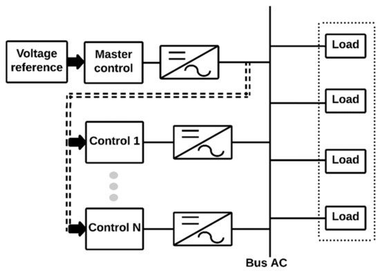
Master and Slave Control
In the configuration shown in Figure 8, a voltage inverter works as master control and adopts the reactive power control method (PQ). When the system works in island mode, the inverter adopts the voltage–frequency control method (V/F) [54,80,81][18][46][47]. In this configuration, the master unit can be classified into three subcategories: battery energy storage system (BESS), DG, and a combination of BESS-DG [54,80,81][18][46][47]. This type of control allows excellent energy performance and voltage recovery at the MG/EPS PCC [80,81][46][47].
Average Load Sharing Control
In the average load sharing control (see Figure 9), each inverter shares the load regulation process. A common bus related to current is used to calculate the average of the current. Each time a current cycle occurs, the system performs a new calculation to average the load. It has two main configurations: single-inverter and parallel-inverter system [83][49].
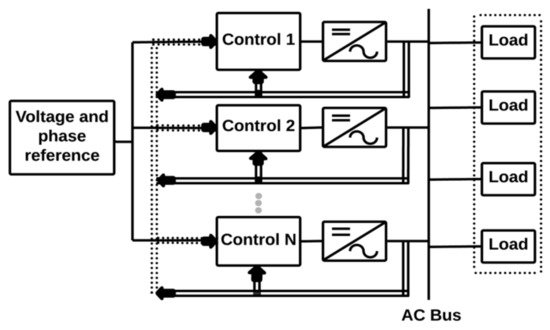
This configuration makes the system reliable due to its ability to distribute the control actions among all inverters. Additionally, it also presents an optimal performance in the current and voltage variables [83][49]. However, it can be affected by the line impedance effect, producing some power losses [83][49].
In [84][50], a distributed control scheme, with current sharing and average voltage regulation in DC MGs, was proposed. The contribution is that the proposed control scheme achieves average voltage regulation without the need for voltage measurements. On the other hand, in [85,86][51][52] a hierarchical control strategy was used for DC MGs with DG.
Ring Control
As can be seen in Figure 10, in this strategy control, a loop is created where a module with its inverter is connected in series to another inverter, using a bus that controls the voltage output. Additionally, a connection is made between the last and the first modules to complete the loop [83][49].
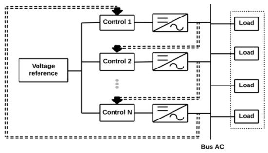
This configuration presents a good response to changes in the system, and it allows for the obtainment of a stable output voltage [83][49]. However, if an inverter fails, the performance of the system is compromised, leading to the possibility of completely disabling the network. It also presents limitations in the electrical capacity [83,87][49][53]. A ring DC MG control architecture was used to manage load balancing and power distribution in [88,89,90][54][55][56].
3. Hybrid MG Topologies
Hybrid MG topologies are divided into AC coupled, AC decoupled, and multiple MGs with their respective subcategories. Each of these topologies is discussed below.
3.1. Coupled AC
AC coupled MGs can have partially isolated or completely isolated configurations. The characteristics of each configuration are described below.
Partially Isolated Configuration
This configuration is generally used to interconnect several asynchronous AC networks. The most typical applications of these topologies are large-scale PV and wind farms. In this configuration (see Figure 11) the AC MG is connected to the EPS in normal operation mode, and low-capacity AC-DC converters are used to handle the energy flow between the EPS and the DC network [2,49,50][11][12][13].
The AC-DC converter that connects the DC network to the EPS is not behind the transformer; therefore, the nominal power of the transformer reduces because it must conduct the flow of energy from the AC network. Therefore, galvanic isolation does not exist for the DC network unless a second transformer is added [2][11]. In this configuration, the protection of devices for DC medium voltage (MV) networks is unusual, and their cost is expensive, so it is not often used because MV networks DC are rarely used in MGs [2][11].
Completely Isolated Configuration
This configuration presented in Figure 12 is divided into three main stages and is more common than the partially isolated configuration. The micro-source stage is the first one, where DG units, ESS, and the DC link are connected. The second one is the combined source, where the inverter and the AC link are located to connect them. Finally, the third stage is the MG, where the low-voltage interconnections and the EPS are carried out [2,49,50][11][12][13].
This configuration compared to conventional configurations strengthens the reliability and flexibility of the distribution network. In addition, its plug-and-play-based system benefits the incorporation of next-generation, charging, or storage devices [2][11].
A transformer between MGs and the EPS is used at the PCC. It supplies galvanic isolation to the MG and decreases the voltage to create AC and DC low-voltage networks [2][11]. Although this configuration is suitable for incorporating DG units in the network, many converters are required to connect the DG AC units to the DC network. However, connecting DG units to the network would improve the efficiency of the configuration [2][11].
3.2. Decouple AC
AC decoupled MGs are divided into the following configurations: two-stage completely isolated, two-stage partially isolated, and three-stage partially isolated configuration. The characteristics of each configuration are described below.
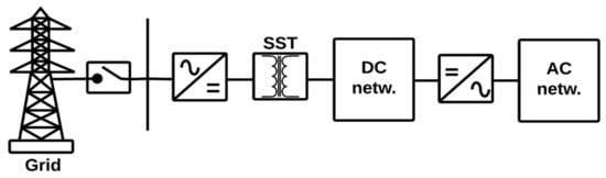
Two-Stage Completely Isolated Configuration
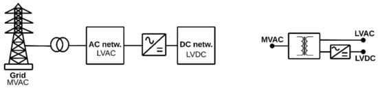
In this configuration, shown in Figure 13, a solid-state transformer (SST) is at the input, supplying galvanic isolation to the MG.
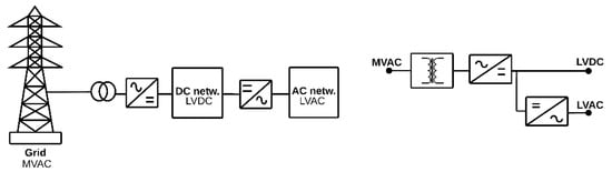
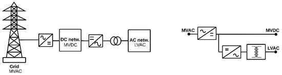
Two-Stage Partially Isolated Configuration
The two-stage partially isolated topology (see Figure 14) (as the AC coupled partially isolated topology), is less usual than the other topologies because the protection of the devices for the DC MV network is not as usual, and their cost is relatively high.
Three-Stage Partially Isolated Configuration
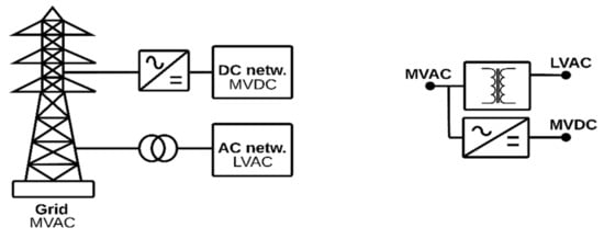
This configuration, represented in Figure 15, provides DC MV and LV networks as well as an AC LV network [2][11]. Additionally, it employs a DC MT network as the two-stage partially isolated configuration.
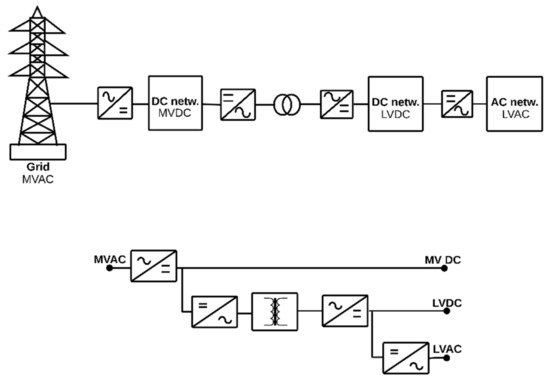
The usage of a medium-frequency (MF) transformer in the DC-DC stage supplies galvanic isolation of the LV side of the MG and the size of the devices is extremely reduced [2][11]. Moreover, the use of an MF transformer makes it suitable for small- or large-scale integration of DG units, ESS, or loads. Nevertheless, it must improve reliability and efficiency while it reduces price and size devices [2,49,50][11][12][13].
3.3. Multiple MGs
Multiple MGs are autonomous, independently managed, and operated systems that allow the use of DG units and loads efficiently. Each MG may have some functions or capacity such as excess renewable generation, which could benefit other MGs in the same area and at different times [91][57].
AC—DC
Figure 16 shows the structure of multiple MGs AC and DC.
Neighboring MGs connected can increase their performance in backup, reliability, economic dispatch, and power quality [43][5]. However, the energy management of multiple MGs system is a complex problem since the DG units within each multiple MG, the energy exchange between the multiple MGs, and the energy exchange between the EPS and the MGs must be coordinated. The development of multiple MG systems is limited by the current energy management capacity [54,91][18][57].
Based on SST
The configuration based on SST (see Figure 17) uses an SST that acts as a power router, which can perform all the functions of a conventional transformer [43][5].
This configuration can coordinate the power exchange between neighboring AC and DC MGs. It offers high-power quality and allows a reduction in the number of faults [43,92,93][5][58][59]. However, the three-phase unbalance problem can cause adverse impacts on the power quality of the SST [92,93][58][59]. Applications that integrated SSTs and DG were studied in [94,95,96][60][61][62].
3.4. -NET
This configuration is based on the union of three different networks, as seen in Figure 18. The first one is a high-quality DC network, the second one is a low-quality DC network, and the third one is an AC network connected to the EPS through a PCC. This configuration is essential for situations where there are constant interruptions and concerns about power quality [39,97][14][63].
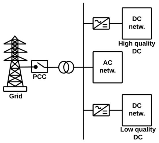
The reliability offered by this configuration is very high. In addition, many loads can be connected to any of the types of networks. For example, it would be feasible to connect a heater to the low-quality DC network and sensitive electronic devices to the high-quality DC network. However, the design and implementation costs of this network are high, and high power losses can be presented [39,97][14][63].
Currently, it is necessary to develop flexible MGs capable of operating both connected to the EPS and in island mode. Therefore, studies about MG topologies, architectures, planning, and configurations are necessary. A challenge of this configuration is the need to integrate new technologies of power electronics, telecommunications, generators, and ESS, among others [47][9].
References
- Bordons, C.; Garcia-Torres, F.; Valverde-Isorna, L. Gestión Óptima de la Energía en Microrredes con Generación Renovable. Rev. Iberoam. Automática E Inf. Ind. 2015, 12, 117–132.
- De Madrid, C.; De, G.; Inteligentes, R.; Energía, D.; Comunicación, Y. La Suma de Todos Guía de Redes Inteligentes de Energía y Comunicación; IDEA: Madrid, Spain, 2004.
- Fuentes, A. Estudio de Viabilidad y Requisitos Técnicos Necesarios Para la Implantación de una Micro-Red Eléctrica. Ph.D. Thesis, Universidad Argentina de la Empresa, Buenos Aires, Argentina, 2007.
- Utkarsh, K.; Srinivasan, D.; Trivedi, A.; Zhang, W.; Reindl, T. Distributed Model-Predictive Real-Time Optimal Operation of a Network of Smart Microgrids. IEEE Trans. Smart Grid 2019, 10, 2833–2845.
- Gupta, A.; Doolla, S.; Chatterjee, K. Hybrid AC–DC Microgrid: Systematic Evaluation of Control Strategies. IEEE Trans. Smart Grid 2018, 9, 3830–3843.
- Lotfi, H.; Khodaei, A. Hybrid AC/DC microgrid planning. Energy 2017, 118, 37–46.
- Baran, M.; Mahajan, N. DC distribution for industrial systems: Opportunities and challenges. IEEE Trans. Ind. Appl. 2003, 39, 1596–1601.
- Xu, L.; Chen, D. Control and Operation of a DC Microgrid with Variable Generation and Energy Storage. IEEE Trans. Power Deliv. 2011, 26, 2513–2522.
- Guerrero, J.M.; Vasquez, J.C.; Matas, J.; de Vicuna, L.G.; Castilla, M. Hierarchical Control of Droop-Controlled AC and DC Microgrids—A General Approach toward Standardization. IEEE Trans. Ind. Electron. 2011, 58, 158–172.
- Justo, J.J.; Mwasilu, F.; Lee, J.; Jung, J.-W. AC-microgrids versus DC-microgrids with distributed energy resources: A review. Renew. Sustain. Energy Rev. 2013, 24, 387–405.
- Unamuno, E.; Barrena, J.A. Hybrid ac/dc microgrids—Part I: Review and classification of topologies. Renew. Sustain. Energy Rev. 2015, 52, 1251–1259.
- Nehrir, M.H.; Wang, C.; Strunz, K.; Aki, H.; Ramakumar, R.; Bing, J.; Miao, Z.; Salameh, Z. A Review of Hybrid Renewable/Alternative Energy Systems for Electric Power Generation: Configurations, Control, and Applications. IEEE Trans. Sustain. Energy 2011, 2, 392–403.
- Nejabatkhah, F.; Li, Y.W. Overview of Power Management Strategies of Hybrid AC/DC Microgrid. IEEE Trans. Power Electron. 2015, 30, 7072–7089.
- Nguyen, M.Y.; Yoon, Y.T. A Comparison of Microgrid Topologies Considering Both Market Operations and Reliability. Electr. Power Compon. Syst. 2014, 42, 585–594.
- Shi, G.; Han, H.; Liu, Y.; Su, M.; Liu, Z.; Sun, Y. A Common Second Frequency Control of Island Cascaded-type Microgrid. In Proceedings of the 2019 IEEE Energy Conversion Congress and Exposition (ECCE), Baltimore, MD, USA, 29 September–3 October 2019; IEEE: Piscataway, NJ, USA, 2019; pp. 5407–5410.
- Sun, Y.; Shi, G.; Li, X.; Yuan, W.; Su, M.; Han, H.; Hou, X. An f-P/Q Droop Control in Cascaded-Type Microgrid. IEEE Trans. Power Syst. 2018, 33, 1136–1138.
- Ge, X.; Han, H.; Xiong, W.; Su, M.; Liu, Z.; Sun, Y. Locally-distributed and globally-decentralized control for hybrid series-parallel microgrids. Int. J. Electr. Power Energy Syst. 2020, 116, 105537.
- Khan, H.A.U.; Al Hosani, M.; Zeineldin, H. Topology planning for autonomous MMGs: An ordered binary decision diagram-based approach. IET Smart Grid 2020, 3, 60–68.
- Hernández Mora, J.; Trujillo Rodríguez, C.; Vallejo Lozada, W. Modelo de un sistema fotovoltaico interconectado. Tecnura 2013, 17, 26–34.
- Fusheng, L.; Ruisheng, L.; Fengquan, Z. Composition and classification of the microgrid. In Microgrid Technology and Engineering Application; Academic Press: Cambridge, MA, USA, 2016; pp. 11–27.
- Trujillo Rodriguez, J. Hernandez Mora OFC. In Sistemas Fotovoltaicos y Sistemas Eólicos en Microrredes; UD E, Caldas U; Microrredes Electr. Primera, UD: Bogotá, Colombia, 2015; pp. 61–83.
- Hayman, A.K. Development of a High-Efficiency Solar Micro-Inverter. Ph.D. Thesis, Massachusetts Institute of Technology, Cambridge, MA, USA, 2008.
- Alvarez, J.M.G.; Targarona, J.C.G. Generación eólica empleando distintos tipos de generadores considerando su impacto en el sistema de potencia. Dyna 2011, 78, 95–104.
- ISE PRIFORSES. Photovoltaics Report; Fraunhofer: Freiburg, Germany, 2020.
- Mongrain, R.S.; Ayyanar, R. Control of nonideal grid-forming inverter in islanded microgrid with hierarchical control structure under unbalanced conditions. Int. J. Electr. Power Energy Syst. 2020, 119, 105890.
- Brandao, D.I.; Araujo, L.; Caldognetto, T.; Pomilio, J.A. Coordinated control of three- and single-phase inverters coexisting in low-voltage microgrids. Appl. Energy 2018, 228, 2050–2060.
- Pinto, J.O.C.P.; Moreto, M. Protection strategy for fault detection in inverter-dominated low voltage AC microgrid. Electr. Power Syst. Res. 2021, 190, 106572.
- Chang, C.-Y.; Zhang, W. Distributed control of inverter-based lossy microgrids for power sharing and frequency regulation under voltage constraints. Automatica 2016, 66, 85–95.
- Andishgar, M.H.; Gholipour, E.; Hooshmand, R.-A. An overview of control approaches of inverter-based microgrids in islanding mode of operation. Renew. Sustain. Energy Rev. 2017, 80, 1043–1060.
- Khan, A.A.; Beg, O.A.; Alamaniotis, M.; Ahmed, S. Intelligent anomaly identification in cyber-physical inverter-based systems. Electr. Power Syst. Res. 2021, 193, 107024.
- Trujillo, C.; Velasco, D.; Figueres, E.; Garcerá, G.; Ortega, R. Modeling and control of a push–pull converter for photovoltaic microinverters operating in island mode. Appl. Energy 2011, 88, 2824–2834.
- Khan, O.; Xiao, W. Review and qualitative analysis of submodule-level distributed power electronic solutions in PV power systems. Renew. Sustain. Energy Rev. 2017, 76, 516–528.
- Lakatos, L.; Hevessy, G.; Kovács, J. Advantages and Disadvantages of Solar Energy and Wind-Power Utilization. World Future 2011, 67, 395–408.
- Awan, M.A.I.; Raza, A.; Riaz, M.; Khalil, L.; Bhatti, K.L. Integration of sub-gradient based coordinate for multiple renewable generators in microgrid. Mater. Today Proc. 2021, 47, S64–S73.
- Willenberg, D.; Winkens, A.; Linnartz, P. Impact of wind turbine generator technologies and frequency controls on the stable operation of medium voltage islanded microgrids. Electr. Power Syst. Res. 2020, 189, 106760.
- Li, H.; Chen, Z. Overview of different wind generator systems and their comparisons. IET Renew. Power Gener. 2008, 2, 123–138.
- Rosslyn-Smith, W.; De Abreu, N.V.A.; Pretorius, M. Exploring the indirect costs of a firm in business rescue. S. Afr. J. Account. Res. 2019, 34, 24–44.
- Gaonkar, D.N. Investigation on Electromagnetic Transients of Distributed Generation Systems in the Microgrid. Electr. Power Compon. Syst. 2010, 38, 1486–1497.
- Thakur, D.; Jiang, J. Design and Construction of a Wind Turbine Simulator for Integration to a Microgrid with Renewable Energy Sources. Electr. Power Compon. Syst. 2017, 45, 949–963.
- Wunder, B.; Ott, L.; Kaiser, J.; Han, Y.; Fersterra, F.; Marz, M. Overview of different topologies and control strategies for DC micro grids. In Proceedings of the 2015 IEEE First International Conference on DC Microgrids (ICDCM), Atlanta, GA, USA, 7–10 June 2015; IEEE: Piscataway, NJ, USA, 2015; pp. 349–354.
- Wunder, B.; Ott, L.; Han, Y.; Kaiser, J.; Maerz, M. Voltage Control and Stabilization of Distributed and Centralized DC Micro Grids. In Proceedings of the PCIM Europe 2015; International Exhibition and Conference for Power Electronics, Intelligent Motion, Renewable Energy and Energy Management, Nuremberg, Germany, 19–20 May 2015; pp. 1–8.
- Dunham, H.; Cutler, D.; Mishra, S.; Li, X. Cost-optimal evaluation of centralized and distributed microgrid topologies considering voltage constraints. Energy Sustain. Dev. 2020, 56, 88–97.
- Jmii, H.; Abbes, M.; Meddeb, A.; Chebbi, S. Centralized VSM control of an AC meshed microgrid for ancillary services provision. Int. J. Electr. Power Energy Syst. 2020, 115, 105450.
- Chandra, A.; Singh, G.K.; Pant, V. Protection of AC microgrid integrated with renewable energy sources—A research review and future trends. Electr. Power Syst. Res. 2021, 193, 107036.
- Carvalho Silveira, J.P.; dos Santos Neto, P.J.; dos Santos Barros, T.A.; Ruppert Filho, E.; Chandra, A.; Singh, G.K. Power management of energy storage system with modified interlinking converters topology in hybrid AC/DC microgrid. Int. J. Electr. Power Energy Syst. 2021, 130, 106880.
- Chen, X.; Wang, Y.H.; Wang, Y.C. A novel seamless transferring control method for microgrid based on master-slave configuration. In Proceedings of the 2013 IEEE ECCE Asia Downunder, Melbourne, VIC, Australia, 3–6 June 2013; IEEE: Piscataway, NJ, USA, 2013; pp. 351–357.
- Wanichrojanarat, C.; Wirasanti, P. Control Strategy for Seamless Transition of Microgrid Using Battery Energy Storage System. In Proceedings of the 2018 53rd International Universities Power Engineering Conference (UPEC), Glasgow, UK, 4–7 September 2018; pp. 1–6.
- Yan, Z.; Zhang, X.P. Master-slave wave farm systems based on energy filter with smoothed power output. Glob. Energy Interconnect. 2018, 1, 559–567.
- Roslan, M.A.; Ahmed, K.H.; Finney, S.J.; Williams, B.W. Improved Instantaneous Average Current-Sharing Control Scheme for Parallel-Connected Inverter Considering Line Impedance Impact in Microgrid Networks. IEEE Trans. Power Electron. 2010, 26, 702–716.
- Trip, S.; Han, R.; Cucuzzella, M.; Cheng, X.; Scherpen, J.; Guerrero, J. Distributed Averaging Control for Voltage Regulation and Current Sharing in DC Microgrids: Modelling and Experimental Validation. IFAC-PapersOnLine 2018, 51, 242–247.
- Benahmed, S.; Riedinger, P.; Pierfederici, S. Distributed-based Integral Action for Current Sharing and Average Voltage Regulation in DC Microgrids. IFAC-PapersOnLine 2021, 54, 52–59.
- Yuan, M.; Fu, Y.; Mi, Y.; Li, Z.; Wang, C. Hierarchical control of DC microgrid with dynamical load power sharing. Appl. Energy 2019, 239, 1–11.
- Wu, T.-F.; Chen, Y.-K.; Huang, Y.-H. 3C strategy for inverters in parallel operation achieving an equal current distribution. IEEE Trans. Ind. Electron. 2000, 47, 273–281.
- Toub, M.; Iii, R.D.R.; Maaroufi, M.; Aniba, G. Decentralized Hamiltonian Control of Multi-DER Isolated Microgrids with Meshed Topology. Energy Procedia 2019, 157, 1253–1265.
- Zafeiratou, I.; Prodan, I.; Lefèvre, L.; Piétrac, L. Meshed DC microgrid hierarchical control: A differential flatness approach. Electr. Power Syst. Res. 2020, 180, 106133.
- Mohammadi, S.; Ojaghi, M.; Jalilvand, A.; Shafiee, Q. A pilot-based unit protection scheme for meshed microgrids using apparent resistance estimation. Int. J. Electr. Power Energy Syst. 2021, 126, 106564.
- Zhao, B.; Wang, X.; Lin, D.; Calvin, M.M.; Morgan, J.C.; Qin, R.; Wang, C. Energy Management of Multiple Microgrids Based on a System of Systems Architecture. IEEE Trans. Power Syst. 2018, 33, 6410–6421.
- Agrawal, A.; Nalamati, C.S.; Gupta, R. Hybrid DC–AC Zonal Microgrid Enabled by Solid-State Transformer and Centralized ESD Integration. IEEE Trans. Ind. Electron. 2019, 66, 9097–9107.
- Li, Y.; Sun, Q.; Qin, D.; Cheng, K.; Li, Z. Power Control of a Modular Three-Port Solid-State Transformer With Three-Phase Unbalance Regulation Capabilities. IEEE Access 2020, 8, 72859–72869.
- Ullah, S.; Haidar, A.M.; Hoole, P.; Zen, H.; Ahfock, T. The current state of Distributed Renewable Generation, challenges of interconnection and opportunities for energy conversion based DC microgrids. J. Clean. Prod. 2020, 273, 122777.
- Mishra, D.K.; Ghadi, M.J.; Li, L.; Hossain, J.; Zhang, J.; Ray, P.K.; Mohanty, A. A review on solid-state transformer: A breakthrough technology for future smart distribution grids. Int. J. Electr. Power Energy Syst. 2021, 133, 107255.
- Huang, L.; Li, Y.; Cui, Q.; Xie, N.; Zeng, J.; Shu, J. Research on optimal configuration of AC/DC hybrid system integrated with multiport solid-state transforms and renewable energy based on a coordinate strategy. Int. J. Electr. Power Energy Syst. 2020, 119, 105880.
- Nguyen, M.Y.; Nguyen, V.T.; Yoon, Y.T. Three-wire network: A new distribution system approach considering both distributed generation and load requirements. Int. Trans. Electr. Energy Syst. 2013, 23, 719–732.
More