Your browser does not fully support modern features. Please upgrade for a smoother experience.
Please note this is a comparison between Version 2 by Rita Xu and Version 1 by Vaclav Novotny.
Carnot batteries are a quickly developing group of technologies for medium and long duration electricity storage. It covers a large range of concepts which share processes of a conversion of power to heat, thermal energy storage (i.e., storing thermal exergy) and in times of need conversion of the heat back to (electric) power.
- medium duration energy storage
- long duration energy storage
- Carnot battery
- pumped thermal energy storage
1. Introduction
The share of renewable generation in electricity production is ever increasing with the feasibility of a 100% renewable supply supported by multiple studies [1,2,3][1][2][3]. The intermittent nature of these sources puts increasing requirements on electricity storage and system flexibility. Lithium batteries are a well-established technology within this field, provide high efficiency (95%, though in real operation, auxiliaries and performance decay by wearing and ageing can notably decrease this value [4,5][4][5]) and relatively low cost per unit power (€/kW). For grid scale medium and long duration applications, however, they are economically well fitted to no more than several hours of capacity due to the high cost per unit capacity (€/kWh). Investigation of a hypothetical 100% of renewable scenario for the UK has found, that, apart from the required installation of certain over-generation, it is the medium duration energy storage in the range of multiple hours to days, through which the majority of the stored electricity needs to flow [6,7][6][7]. The lifetime of electrochemical batteries, typically below 10 years, furthermore stresses the need to search for other solutions [8].
Currently, pumped hydro energy storage (PHES) largely dominates the installed storage capacity in comparison to other solutions, as weauthors can see in Figure 1. Even though a rapid growth is experienced in electrochemical batteries and is also expected across other technologies [9], the logarithmic scale provides an idea of the overall storage power demand when the total installed capacity will need to increase several fold to accommodate the renewable production variation. The values are compiled from the database [10] with further added Carnot battery projects known to the authors, with respect to the year 2020. It might not be exhaustive, especially in case of the electro-chemical batteries, though it provides a good overview of the situation and the scale of storage for future energy systems. One can also observe that some systems classified as Carnot batteries are already operational, though only in the megawatt scale.
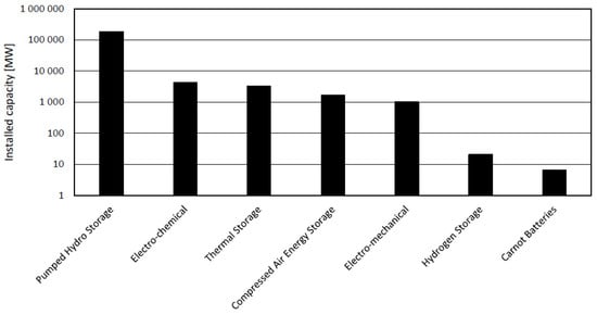
Figure 1. Overview of global installed grid scale electricity storage systems power rating in 2020.
The PHES is also the most commonly employed large scale storage (>100 MW) for medium to long durations. The PHES has major advantages such as high roundtrip efficiency, fast response time, long duration of operation and low self-discharging effect. However, the PHES suffers from the requirements of a suitable geographical location, impact on the environment and low energy density [11,12][11][12]. Compressed air energy storage (CAES) technology utilizes mostly underground caverns for storing large volumes of compressed air. Together with PHES it is therefore dependent on geographically suitable locations [13]. Nowadays, only two commercial large scale CEAS facilities are operating, Huntorf in Germany and McIntosh in Alabama, USA, having installed a capacity of 290 MW and 110 MW and reaching an efficiency of 42% and 54% respectively [14,15][14][15]. Both commercial CAES plants come under the first stage of development, but advanced CAES systems have been developed such as adiabatic-CAES (A-CAES), advanced adiabatic-CAES (AA-CAES) and isothermal-CAES (I-CAES), which aim for higher efficiency by being more sophisticated and complex [16]. AA-CAES has been technologically experimentally proven on the MW scale [17] and current development and construction plans are given for up to 2.3 GW and 28 GWh in the coming years [17,18][17][18]. Flow electrochemical batteries aim to eliminate some drawbacks of classical batteries, especially in capacity scaling, while retaining their advantages. Owing to notably lower efficiency, low energy density, degradation, still requiring toxic and scarce materials and technical flaws and shortcomings, there is a lot of research needed for actual widespread application [19]. Gravity storage systems are also either limited by geographical location or capacity. An increasing number of systems are progressing from conceptual to pilot and commercial stages [20,21][20][21]. Conversion to hydrogen and other synthetic fuels remains costly with very low efficiency and suitable for rather very long duration to seasonal applications [22].
1.1. Carnot Battery Principles
Carnot batteries (CB) comprise a set of multiple technologies which have a common underlying principle of converting the electricity to thermal exergy, storing it in thermal energy storage (TES) systems, and in a time of need converting the heat back to electricity. Based on this principle, alternative terms are also used as power to heat to power (P2H2P) or electric thermal (or electro-thermal) energy (electricity) storage (ETES). An excellent review work [23] provides a general overview of CB principles and therefore the reader is referred to this work for details. Prospects of PTES system are then provided in [24]. Here the general aspects will be therefore summarized rather briefly. A general principle of the CB is illustrated in Figure 2.
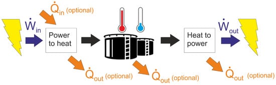
Figure 2. General principle of Carnot battery systems.
Carnot Batteries use surplus electricity as an input of a power to heat (P2H) system to create a temperature gradient (thermal exergy). It can have a form of hot and cold storage systems, or just one of those (hot or cold) with the temperature gradient defined against the environment. During the discharging process, the thermal exergy is converted back to work (electricity) by heat to power (H2P) system, in principle a heat engine. Various concepts of CB can be illustrated regarding the P2H and H2P conversion processes and thermal integration of the heat source in Figure 3.
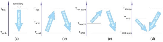
Figure 3. CB concepts regarding thermal integration of heat sources and conversion systems. (a) direct heat to power conversion, (b) reversible thermodynamic cycle, (c) with heat source integration and hot storage or (d) cold storage.
The simplest concept is the direct conversion of electricity to heat, which is then stored before its conversion back to power during discharging, typically by a power cycle. Other systems can be considered so called compressed heat energy storage (CHEST) or pumped thermal energy storage (PTES) as they utilize the thermodynamic cycle (in principle a heat pump) for the P2H conversion. The first PTES in Figure 3b works mostly between two distinct temperature levels arbitrarily chosen and (theoretically) independent of the environment, having separate hot and cold storage systems. A specific aspect of CB is the possibility of thermal integration, both on the side of energy input as well as output, providing many possibilities for sector coupling. Regarding the heat input, the heat source can be either upgraded to a higher temperature, which is then used as a heat input of the power cycle or the charging system can prepare cold, which is stored and subsequently used as a heat sink of the power cycle during discharging, increasing the overall temperature gradient of the heat source [25]. A specific case can be defined when the Tsource is identical to the environment. Regarding hot storage, such systems are not really considered due to their low roundtrip efficiency. Regarding cold storage, it could be considered a highly simplified representation of liquid air energy storage, when the air is liquefied and stored at cryogenic temperatures. All real thermodynamic conversions depart from the ideal ones (e.g., minimum temperature differences in heat exchangers, efficiency of compressors and expanders, pressure drop in components). As a result, a portion of the heat needs to be rejected into the environment due to the irreversibilities [26]. The first concept (Figure 3a) minimizes the losses by converting and storing the heat at highest possible temperature, maximizing the power cycle efficiency. The second concept (Figure 3b) then optimizes the charging and discharging cycles to minimize the irreversibilities. In the heat source integrated concepts, efficiency is also a function of the temperature lift of the heat pump. With a very low lift, the roundtrip efficiency (defined below) can theoretically reach values above unity, in case of a zero lift (and work) of the heat pump, even going towards infinity.
As Dumont et al. [23] or Steinmann et al. [27] mention, there are many possible technological variations of CB. Charging can be realized besides direct conversion (joule heating) by any thermodynamic heat pump cycle. Discharging offers a similar range of options with heat engines to those of Brayton, Rankine or Stirling cycle, their combinations and also direct conversion as thermoelectric, thermi-ionic and thermophotovoltaic systems.
The first examples of these technologies can be traced to 1924, when Fritz Marguerre patented his own solution of thermal energy storage [28] or even to 1833 to work of Erricsson [23], but it has not been until the recent decade, when high volatility of electricity production and its mismatch with demand, it attracted wider interest in this technology. It typically provides relatively low efficiency in the range of 30% to 70% but also low cost for medium and long duration electricity storage. The widely increasing interest in CB was also a reason for establishing an IEA Task 36 on Carnot Batteries [29] with an aim of providing and unifying clear definitions, key performance indicators and classification of CB.
CB as any electricity storage system is specified by its roundtrip efficiency (RTE), which is defined as a ratio between electricity produced during discharging and electricity consumed during charging, see Equation (1).
(1)
Alternatively, useful energy efficiency (also referred to as total efficiency) can be defined by Equation (2) as total useful energy output in the case of sector coupling, especially also providing heat and/or eventually cold. This heat can be used from the CB system in the charging phase, separately drawn from storage, but the highest efficiency is obtained if it is a by-product or rejected heat (possibly also its part) from the discharging phase.
(2)
Note that no heat input is considered even though in some CB concepts it is present. It can be argued that other formulations of efficiency may be also used. From thermodynamic standpoint, exergy efficiency explains the loss of potential and quality of all inputs in the best manner.
2. Carnot Battery Development by Technologies
2.1. Rankine Cycle Systems
Rankine cycle systems can be further divided into steam Rankine cycles, which are predetermined to work efficiently at higher heat source temperatures and high power outputs typically in the order of dozens to hundreds MW and organic Rankine cycles (ORC), which are the domain of smaller power outputs and lower heat source temperatures up to several MW and possibly down to the kW scale. CO2 cycles, typically with transcritical operation, make up a specific category. Considering the underlying principle, even systems, where the Rankine cycle thermodynamic changes are separated to different time periods, are included here. A typical example is storing heat in a liquefied gas or vapor (latent heat), while the gas itself is a working fluid in the thermodynamic conversion.
Table 1 comprehensively summarizes the CB systems utilizing the Rankine cycle for its discharge phase in the scope of commercial development (or having some commercially oriented aspects). They are sorted according to the power to heat conversion method to the resistance heated systems and fully reverse systems; then by working fluids from water to organic fluid, air and CO2 and finally to systems with a Rankine cycle heat pump as a full cycle and the systems with part of the heat pump cycle with liquefaction and storage of the working fluid. Note that eight out of 13 reported systems are conducting experimental, demonstration or even pilot operations of their systems.
Table 1. List of commercial development projects in CB using Rankine cycle discharging.
| Company, System | Charging Method | TES | Discharging Method | Power Output | Storage Capacity/Duration | Roundtrip Efficiency | State | Ref. | |
|---|---|---|---|---|---|---|---|---|---|
| Siemens Gamesa, ETES | Resistance heaters to air | Volcanic rock bed~600 °C | steam Rankine cycle | units to 100s MW | 24 h | 25% to >40% | Demo | [32,33,34] | [30][31][32] |
| RWE, Store2Power | Resistance heaters | molten salt | steam Rankine cycle | 100s MW | hours | ~40% | n.a. | [35] | [33] |
| E2S Power | Resistance heaters | Graphite-aluminium alloy at 700 °C | steam Rankine cycle | 1–100s MW | hours | 25–40% |
Liquid air energy storage (LAES) is in principle also a Rankine cycle as it utilizes the phase change of the working fluid for storage and especially in the discharging phase, a typical cycle’s heat input/output takes place. The working fluid is at the same time also a storage media in an open cycle. The air is compressed and liquefied during the charging by a relatively standard industrial technology. Special attention is paid to the conservation of thermal energy during the liquefaction process, both cold and hot, as it is essential for the high roundtrip efficiency of the system. Thermal energy is in this concept stored therefore threefold—in the liquefied air and near-ambient pressure as latent heat, thermal energy recovered after compressors’ outlets and cold energy from the gas cooling before expansion and from recycled streams.
The advantage of LAES lies in relatively small storage volumes (in the order of 700 times smaller than those required for CAES) due to the higher energy density in liquid air. The LAES system also relies on commonly used components in industry (compressor, liquefier, turbine, etc.). Today’s studies show that it is possible to achieve roundtrip efficiencies around 70%, with a specific investment cost of 1270–2090 €/kW [78][77]. To date, several studies have been published on various LAES configurations. In [79][78] they proposed integration with a conventional combined cycle power plant; in [80][79] they studied the LAES system integrated with a nuclear power plant, and many publications paid attention to the recovery of waste heat from LAES using ORC, which increased RTE by up to 12% [81,82,83][80][81][82].
The only commercial development is carried out by the British company Highview power. In 2011 their first pilot plant was launched (350 kW/2.5 MWh), which was tested on a biomass plant site and is now located at the University of Birmingham. The achieved roundtrip efficiency was only 8%, therefore the second Pilsworth Grid Scale pilot power plant (5 MW/15 MWh) was built in 2018. Highview power is now developing a 50 MW commercial plant in Carrington Village with a storage capacity of 250 MWh in cooperation with MAN Energy Solutions. The commissioning is expected in 2022 [44,45,46][42][43][44]. Another project is planned with the expected start of construction in 2023 in Chile with a power rating of 50 MW and a capacity of 500 MWh [84][83]. In the future, Highview power plans to offer LAES systems in a relatively large range of outputs from 20 MW/80 MWh to more than 200 MW/1.2 GWh [85][84].
Rather favorite among CB appears to be the utilization of CO2 cycles, which otherwise struggle to find their place in other energy systems. Development of the ETES system of MAN and ABB aims at a very peculiar and rather low temperature system with a reversible transcritical CO2 Rankine cycle. The system has the highest storage temperature only around 120–150 °C utilizing pressurized water and cold storage, and using ice as PCM. The hot storage system is divided into four tanks at different temperatures into which the heat is transferred via three separate heat exchangers. It is to balance the optimal mass flow rate and heat exchange temperature profiles due to the change of the supercritical CO2 heat capacity, while the temperature differences along the whole length of the heat exchangers are designed in order of several Kelvins. Only one hot water tank needs to be pressurized, while the pressure is still moderate. During charging, part of the energy in high pressure CO2 is recovered by a hydraulic turbine while rest below the saturation line is flashed to exclude the issues of two-phase expander. The resulting system is then a result of many techno-economical optimizations under constraints of isentropic efficiency of key turbomachinery components (the company’s state-of-the-art) with the roundtrip efficiency reaching values of 38%–50%. The target size is an 8.5 MWe system with 8 h charging. Development of this system is well documented in [31,47,48,49][45][46][47][48]. Currently, an MW scale laboratory demonstrator has been developed to test the system and equipment. The commercialization strategy aims at the possibility to use also standalone system of only heat pump or heat pump with storage, able to provide 5–50 MWth of heat (3–30 MWth cooling) with 2–15 MWe power input. As such, a 50 MWth seawater heat pump for district heating using this technology is to be built in Denmark by 2023 [86][85].
The MAN–ABB consortium is not the only one representative of CO2 cycle utilization, even though they are clearly closest to application. Echogen [50][49], known mainly for its waste heat recovery 8 MW unit with CO2 as a working fluid is also working on a CB system for more than 4 h and 10 MWe size. Available information discloses a concept utilizing the CO2 reversible recuperated cycle, low temperature storage also being ice/water storage (as brine for −2 °C to −10 °C) and high temperature storage being at 300–350 °C in the form of sand in silos or alternatively concrete blocks. The temperature has been selected to be within the limits of standard construction materials [51,52,53][50][51][52]. A proof-of-concept in a 100 kWth scale heat pump and sand storage and heat transfer system has been developed while a 25 MWe 8 h prototype system is in a design phase [54][53].
The CO2 has been also proposed for a system using a similar principle to the LAES by the company Energy Dome [55][54]. The gaseous CO2 is stored at ambient pressure in a large container (dome). During charging, it is compressed, liquefied and stored in tanks, while the heat (from intercooling and condensation) is separately stored in a TES. The discharging process then reverses the flow, high pressure CO2 is evaporated by the stored thermal energy and expanded in the turbines back to the low pressure gas store to produce the electricity. The sequence of charging and discharging can be considered as thermodynamic changes in an open Rankine cycle. To maintain constant conditions at the compressor inlet, a flexible membrane is employed within the dome. TES is separated into five sections at different temperatures in configuration with a multiple section compressor and turbine with intercooling and reheating. Main advantages of this concept are mentioned as high energy density at moderate pressures. The calculated net roundtrip efficiency can reach about 77% [56][55]. Note that similar systems were proposed before, but with liquid CO2 storage at a low pressure and with a maximum roundtrip efficiency of 57% [87][86]. The system has recently progressed from a concept with basic sizing and costing to the construction of a 2.5 MWe/4 MWh pilot system scheduled to be finished in 2022 and in the same year there is planned the start of a full-scale 20 MWe/100 MWh system construction [88][87].
2.2. Brayton Cycle Systems
Brayton cycles are favored for applications with sensible heat TES materials as during the isobaric heat addition and rejection, it is possible to obtain a well matching temperature profile, minimizing exergetic losses. Other advantage can be the maturity of the gas turbine industry, from which many systems are derived. The summary of the commercial development in Table 2 shows that the extent of the projects is smaller than in the case of the Rankine cycle systems (opposite trend to the publications numbers in academic research). It can be argued that one reason is in the requirement of very high efficiency of compressors and expanders to which the systems are highly sensitive, while such components have a limited industrial supply.
Table 2. List of commercial development projects in CB using Brayton cycle discharging.
| Company, System | Charging Method | TES | Discharging Method | Power Output | Storage Capacity/Duration | Roundtrip Efficiency | State | Ref. | |||||
|---|---|---|---|---|---|---|---|---|---|---|---|---|---|
| 247Solar, Heat2Power Turbine | Electric resistance heaters | Silica sand | Gas turbine (Brayton cycle) | 200 kWe–100s MW | 6–20 h | 30% | Concept, design | [89,90] | [88][89] | ||||
| 1414Degrees, TESS | Electric resistance heaters | Silicon based alloy, melting temperature 1414 °C | Gas turbine (also steam turbine, Stirling engine, direct heat) | 10 MW-GW | n.a. | n.a. | Demos (done) Planning grid scale pilot |
[91] | [90] | ||||
| Peregrine Turbine Technologies | Electric resistance heaters | Graphite-aluminium alloy (MGA), 800 °C | CO | 2 | Brayton cycle | 1 MW | lab proof of concept | [36] | [34] | ||||
| Spilling | Steam compression & liquefaction | Saturated water (steam accumulators) | Steam expander (steam engine) | up to MW | hours | n.a. | n.a. | [37,38] | [35][36] | ||||
| GE, AMSESS | CO | 2 | Brayton + el. heating | Molten salt, water tank | Steam cycle with extraction | 20–100 MW | 8 h | 42–62% | Concept | [39] | [37] | ||
| Consortium CHESTER | Heat pump (organic fluid) | PCM and water | ORC | MW scale (8 kW exper.) | hours to days | n.a. | lab proof of concept | [40] | [38] | ||||
| Climeon | Heat pump (organic fluid) | water (e.g., district heating system) | ORC | 80 kW to MW | hours | 25–60% | concept with existing ORC | [41] | [39] | ||||
| TC Mach | Heat pump (organic fluid) | Stone dust TES | ORC | kW | hours | n.a. | construction of proof of concept | [42] | [40] | ||||
| Future Bay | Heat pump (organic fluid) | water (hot) and PCM (cold) | ORC | 10s kW | hours | n.a. | Demo | [43] | [41] | ||||
| Highview | Air liquifaction | Liquid air + other TES | Vaporization, expansion turbine | 50–350 MW | about 6 | 60–70% | Pilot, full scale construction | [44, | [ | 45, | 42 | 46] | ][43][44] |
| MAN/ABB, ETES | CO | 2 | heat pump | 120 °C water + cold (ice) storage | CO | 2 | Rankine cycle | several MWe | ~5 h | ~45% | lab demo | [31,47,48,49] | [45][46][47][48] |
| Echogen, ETES | CO | 2 | heat pump, fluidized bed heat exchange | Sand (hot) and ice (cold) | CO | 2 | Rankine cycle | 25 MW | 250 MWh | ~60% | design | [50,51,52,53,54] | [49][50][51][52][53] |
| Energydome, CO2 battery | CO | 2 | compression & liquefaction | Liquid CO | 2 | + other TES | Vaporization, expansion turbine | 10–80 MW modules | 20–200 MWh | 77% | Pilot construction | [55,56] | [54][55] |
2.1.1. Electrically Heated RC Systems
Joule heating makes most technical sense in combination with a steam Rankine cycle. No other working fluid is considered in these directly heated systems. The reason, except for being the industrial standard, can be found in its higher efficiency compared to ORC systems and the fact that CO2 cycles at high temperatures have seen only very few demonstrators built so far (e.g., CSP application [57][56] or Allam cycle for gas combustion [58][57]). Technically, the direct heating with steam cycle can be considered as the simplest technology. Furthermore, all electrically heated systems under development include the possibility of converting existing coal fired power plants to storage systems, utilizing the existing infrastructure and saving the typically costliest components of the CB, which is the power cycle unit. The system of this type is referred to as a straight forward one in [59][58] and the possible scale in the case of a fossil fired plant’s partial refurbishment for increased flexibility or complete refurbishment can be found in [23].
Regarding the power output, electrically heated systems are well scalable, with the limitations provided by steam cycle systems. The smallest systems in the MW scale can be applied for example in CHP plants; as solely power to power CB, Siemens Gamesa with an output of 1.2 MWe serves only as a demo. The largest systems can theoretically consist of blocks of several hundreds of MW each. Electrically heated storage is limited by relatively low roundtrip efficiency, which is determined mainly by the H2P conversion technology (power cycle efficiency) since the electric heater is employed for charging. Furthermore, the other losses occur during operation, namely heat loss into the environment and the pressure drops.
The first small scale Gamesa ETES test rig was built in Bergedorf in 2014 with 5 MWh storage capacity and a 750 kW gas burner. Its purpose was the testing of various storage concepts, materials and setups. This testing unit has run for over 2500 h [32][30]. Owing to the constructed full system demonstrator, the ETES system of Siemens Gamesa commissioned in 2019 in Hamburg is perhaps the best known; first and so far, the biggest constructed system of this kind. The system uses a horizontal flow packed bed of volcanic rock and air as a heat transfer fluid. With a maximum storage temperature of up to 750 °C the system has 130 MWhth storage capacity. Volumetric storage capacity reaches approximately 0.2 MWhth/m3 (depending on charge-discharge temperature spread) and its great advantage is in high technology readiness level (TRL) due to the use of commercially available components, the resistive heaters from process industry and heat recovery steam generators (HRSG) utilized in combined cycle power plants. The storage concrete construction vessel is filled with about 1000 tons of crushed volcanic rocks and thermally insulated by aerated concrete and rock wool insulation [32][30]. The system was designed for 24 h charge and 24 h discharge operation. The rather low roundtrip efficiency (around 25%) is due to the steam cycle efficiency (small scale, low pressure) and auxiliary loads, especially air fans.
Thermal losses can be minimized by optimizing the amount of thermal insulation according to the economics. Pressure drops can be mitigated by packed bed construction and operation (air flow velocity, particle shape and diameter and vessel length to diameter ratio). Nominal storage capacity can further decrease by de-stratification effects due to heat transfer in a packed bed in a charged state [60][59] (reported for horizontal flow stores). Hence the storage unit must be oversized, which leads to an increase of thermal and pressure losses. Unlike in coal plants, parasitic loads related to its handling or boiler efficiency are however excluded here. The efficiency is expected to significantly increase in larger scale installations to over 42% [33,34,60][31][32][59]. Currently, Gamesa is ready for building the first series of commercial pilots in a range of 10–100 MW power; 100–2000 MWh storage capacity and 300–720 °C steam temperature [32][30].
The ETES system offers various applications, such as integration into existing power plants or combined heat and power plants, rebuilding conventional fossil fuel power plants into storage units or electrification of process heating. Therefore, Siemens Gamesa has been developing three market types of storage application, for the conversion of fossil power plants, adding storage to existing thermal systems (industrial plants for process heat electrification and heat recovery) and a whole stand-alone system supplying process steam, electricity or district heating [60][59].
Looking at the chosen horizontal configuration, much smaller scale investigations of rock bed TES found very strong effects of buoyancy, having a detrimental effect on temperature stratification and the utilization of the thermal capacity of the entire volume, further confirming the de-stratification effects. Either the TES capacity is then limited or additional horizontal air tight layers need to be added to the storage tank to maintain air flow uniformly through the entire volume [61][60].
Similar is the intended application scale of RWE’s development, which is, with its project StoreToPower, focusing on an alternative technology of molten salt, adopted primarily from concentrated solar power plants (CSP) and, secondarily, also on solid materials with air as a heat transfer fluid [35][33]. However, no further public information provides any insight on the ongoing status. Focus on molten salt appears to be a logical choice as in the CSP plants it is a well proven commercial technology [62,63][61][62]. With the molten salts, special attention needs to also be paid to corrosion, especially at temperatures above 500 °C [64,65][63][64], which are typically found in coal fired power plants.
A P2H2P system with direct electrical heating primarily suggested for refurbishment of coal fired plants is offered by E2S Power [36][34]. The TES system is using an alloy (miscibility gap alloy, MGA) composed of graphite and aluminum and developed by a partner MGA Thermal. The MGAs are commonly proposed as a novel type of TES material with some unique properties such as macroscopically solid materials safely embedding PCM, providing combination of sensible and latent heat and with high thermal conductivity [66,67][65][66]. Blocks of the MGA are electrically heated during charging, half up to 700 °C while the second half only to temperature required by the steam turbine. The colder blocks then, during discharging and steam generation, serve for self-regulation of the steam outlet temperature. A laboratory system has been built demonstrating the TES with charging and steam generation, while plans exist for a 50 MWhth pilot at a coal power plant in Montenegro.
2.1.2. Reversible RC Systems
Reversible systems use the principle of a vapor compression heat pump in the charging phase and standard RC during discharging. Various configurations were proposed theoretically for steam systems with a suggestion to further improve the roundtrip efficiency by integration of heat sources to the heat pump input [68][67]. Together with the additional possibility of various working fluids (steam, organic fluids, CO2), direct or indirect use of the cycle working fluid for storage and choice between latent or sensible TES, there is a wide range of available technologies.
Starting from the most typical RC using water as a working fluid, the company Spilling, manufacturer of steam turbines, compressors and engines, entered into the development of CB. The system consists of a reversible steam engine/compressor and two steam accumulators, one at low pressure and other at high pressure [37,38][35][36]. A major advantage of such system is a combination of existing technology of steam engine from the company portfolio, while steam accumulators are a well-established technology over hundred years old. The accumulators however require relatively large, pressurized tanks for the saturated water. This makes the technology of steam accumulators suitable rather for industries and small power plants; one of the largest applications is a 20 MWth (50 min at 5.5 MWe) application for a CSP plant. The addition of PCM to the tanks is proposed to improve the thermal capacity at the same volume. A drop in the pressure during the discharging of the tanks is another disadvantage [69,70][68][69]. For the CB applications, a similar size can be expected as that for similar systems for small steam parabolic trough flexible plants as 2 MW/6–24 MWh units [71][70]. The pressure drop loss might be partly compensated for by sliding pressure in both charging and discharging process. Investigation of parameters of this CB concept are not, to the authors’ knowledge, supported by any scientific literature.
GE has in the past proposed a system using a recuperated CO2 Brayton cycle operating as a heat pump for charging with a steam Rankine cycle discharging as an advanced molten salt electrical storage system (AMSESS). High temperature heat is stored as a molten salt while low temperature heat input is provided from a water tank and the water is thus cooled down. An additional electric heater can be used to increase the salt temperature. During discharging, heat is transferred to the steam cycle, where most of the rejected heat goes into the environment, while a smaller portion such as a turbine bleed heats up the water tank. A design with off-the-shelf components has been performed for 20–100 MWe power output over 8 h period with RTE ranging based on size and presence of the heater between 42% and 62%. An interesting note is that the space requirements are about one third of the same capacity in containerized lithium batteries [39][37].
Another set of technologies builds on standard heat pumps and subcritical organic Rankine cycles. These systems are specifically considered as well fitted to waste heat sources, or other low temperature heat sources, such as solar collectors or geothermal heat. The availability of the heat source then decreases temperature lift of the heat pump (or provides a heat source in less considered concept, where the heat sink is below ambient by cold energy stored and prepared in time of excess electricity by refrigeration cycle). Roundtrip efficiency can, as a result of heat input, theoretically exceed 100% [72][71]. Regarding the size and cost, storage tanks need to be carefully considered as in the case of low temperature glide; even a small power output requires large tanks, which might be costly for long duration storage. The power output can be expected from dozens kW up to no more than several MW as is the size of large CHP or geothermal ORC systems [73][72]. This concept gained much research attention, where theoretical investigations are performed in many institutes and several experimental systems are in experimental operation or under construction [74[73][74][75],75,76], all in kW scale.
Looking at the commercial development, the list is, however, rather short. Within the CHESTER research project [40][38], universities join research institutes and companies to focus on business models and market opportunities for such application, meanwhile one industry within the project, for example, focuses on the development of an isobaric expansion device considered for one of the concepts [77][76]. The main CB concept utilizes both sensible and latent heat storage to maximize efficiency and match temperature profiles during charging and discharging, while providing thermal integration to district heating. A kW scale experimental system is under development. Similarly, ORC unit manufacturer Climeon offers its units of output around 100 kWe for CB applications with storage also proposed as district heating infrastructure including large seasonal storage tanks and up to MWe size total output. Additionally, greenhouses and geothermal systems are suggested as application cases for CB. Except for the ORC conversion unit, the system is however in a conceptual state [41][39]. Another example is a heat pump manufacturer, TC Mach, developing together with a university a high temperature heat pump, TES. made of compacted stone dust and an ORC, where the constructed proof of concept unit is going to be sub-kW scale [42][40].
The only larger scale ORC CB system in state of a pilot application is developed by Futurebay [43][41]. This system is considered in several applications, with or without thermal integration of waste heat source. Without any external heat source, a heat pump is used to charge both hot and cold storage during a period of excess electricity and these stores are then utilized separately. Heat is stored in hot water tank while PCM storage (probably ice based) is used for cold storage. Both hot and cold can be used directly or the ORC can run between present temperature gradients—hot store and ambient (eventually space heating temperature) or waste heat to cold store. The system is considered primarily for integration into thermal systems with both cooling and heating requirements. A containerized demonstrator delivering 50 kWe/200 kWhe and cooling capacity 2 MWhth has been built and operated; scalability is however suggested up to a 12 MWe/72 MWhe grid scale system.
| 8 MWh | |||||||||||||
| 45% | CO | 2 | turbine/compressor tests | [ | 92 | ] | [ | 91] | |||||
| Isoentropic | Heat pump (Brayton cycle -reciprocating devices) | Crushed rock packed bed | Brayton cycle (reciprocating devices) | 2 MW (exper. 150 kW) | 16 MWh | 72% | Demo (bankruptcy) |
[93] | [92] | ||||
| Malta, Pumped Heat Energy Storage | Heat pump (reverse Brayton cycle) | Molten salt + hydrocarbon antifreeze | Recuperated Brayton cycle | 10–100 MW | 80 MWh–1 GWh | n.a. | Concept, design | [26] | |||||
| Stiesdal, GridScale | Heat pump (reverse Brayton cycle) | Crushed basalt rock packed bed | Brayton cycle | 2 MW–1 GW | 100,000 MWh | 35–60% | Pilot construction | [94] | [93] | ||||
| Enolcon, OPTES | Heat pump (reverse Brayton cycle), N | 2 | or Ar | Silica sand packed bed (silica sand, iron based sand, basalt) | Brayton cycle, N | 2 | (or Ar) | ~8 MW | ~80 MWh | 58–66% | Concept, design (Pilot designing/ constructing) |
[30] | [94] |
| WindTP | Heat pump (reverse Brayton cycle) | Gravel bed, indirect heat transfer | Brayton cycle | 3–20 MW | up to 100 h | up to 85% | component demo | [95] |
2.2.1. Electrically Heated BC Systems
In order for the electrically heated Brayton cycle to be efficient, very high storage temperatures need to be reached, namely exceeding 1000 °C. However, the need of reaching such a high temperature for increase in roundtrip efficiency also leads to material constraints. Considering a parallel to the scientifically reported development in Brayton based PTES, interestingly, a very small number of publications is focusing on this concept.
A U.S. company, 247 Solar, provides a concept of an electrically heated CB, which combines subsystems named the 247Solar Heat2Power Turbine and the 247Solar Thermal Storage System. These subsystems are proven in CSP applications (Brayton based solar towers), where there is a specific solar irradiation receiver and vertically orientated thermal storage, both using air as a heat transfer fluid operating under conditions of near ambient pressure and high temperatures (970 °C) [90][89].
During charging, the electric heater (resistance coils) is employed for heating the air flow by using a blower, both supplied by surplus electricity, and afterwards the air passes the heat to the sand thermal storage. The discharging process employs a classic open loop Brayton cycle, meaning that the inlet ambient air is compressed, then heat is supplied in two heat exchangers (low and high temperature) and next the air expands in the turbine. To increase the overall system dispatchability, a burner for various types of fuel (including hydrogen) can be added. The presented roundtrip efficiency of this system amounts to 30%, nevertheless the combined heat and power production efficiency can reach more than 90%. 247 Solar considers standard configuration with nominal 200 kWe power output and thermal storage capacity 1.8 MWh that corresponds to 8–10 h duration. This project is evolving in collaboration with Capstone Green Energy, the provider of customized microgrid solutions and on-site energy technology systems [96].
1414 Degrees Limited is an Australian company, which develops Thermal Energy Storage Systems (TESS). The novelty of this system lies in using molten silicon PCM with melting temperature 1414 °C, which enables reaching high energy densities and potentially high efficiencies of conversion back to electricity and usable heat [89][88].
For the charging of TES, an electric resistive heater is utilized. Another option for heating the molten silicone storage is combusting gas, for instance, methane generated from wastewater plants. The advantage of using silicon is in its high latent heat capacity in comparison to other PCMs. The silicon’s sensible heat capacity below the melting point is up to 300 kWh/t; nevertheless, the latent heat supplied during the solid to liquid phase change at the constant temperature of 1414 °C is about 500 kWh/t. The operation of TES at such a temperature brings many material challenges. However, several well-established industrial processes are treating material with very high temperatures, for example the cement industry temperature level exceeds 1400 °C. Therefore, 1414 Degrees implements materials and technology knowledge from these proven technologies. The discharging process can be achieved by several conventional heat engines, where the most effective plants achieve over 60% thermal efficiency. Hence, 1414 Degrees considers four options of discharging. In terms of combined power and heat production for reaching the maximum overall roundtrip efficiency, the gas turbine, steam turbine or a Stirling engine can be employed; lastly, a steam generator or heat exchanger can provide steam or hot clean air for industrial processes [89][88].
The TESS is designed as a modular system; when connected in series it increases the power output and in parallel configuration the storage capacity rises. 1414 Degrees plans four main commercial applications; one oriented on bulk medium-long term energy storage, one providing medium scale energy storage for industries and residential developments requiring power and heat. The last one is developed to accommodate combustion waste gas (e.g., sewage treatment) and store the thermal energy for later recovery (for electricity and heat). As such, it is similar to the industrial application but with modified charging. Lastly, the TESS industrial system producing steam is best fitted for industries with high thermal rather than electricity demand, especially for replacing natural gas with renewable sources. Using a steam turbine for electricity generation is only secondary [91][90], but possible for example using extraction turbines providing also heat at lower parameters.
1414 Degrees built up the first demonstration plant in 2016 and is still operating it in its R&D facility in Lonsdale, South Australia. The demo comprises of 200 kg silicon PCM storage charged by 50 kW heater and was using 43 kW Stirling engine for discharging, in 2018 replaced by a gas turbine. In 2018, a 10 MWhth GAS-TESS module was also put in operation at the Glenelg Wastewater Treatment Plant. The next step of 1414 Degrees is to acquire SolarReserve Australia II, which owns the Aurora solar project [97]. The current plans of the Aurora project, led by the 1414 Degrees company, are to build up a 70MW PV farm and 150 MW CSP plant, coupled with several thousand MWhth storage capacity [98].
The use of a supercritical CO2 in a BC has been proposed by Peregrine Turbine Technologies as a CB along several other use cases [92][91]. The system uses the MGA from MGA Thermal as already considered in Rankine cycle systems from E2S, here with temperatures of 800 °C. The power cycle uses a partially recuperated configuration with compression from right above the CO2 critical point [99] and the whole system is designed as a 1 MWe modular system with a storage capacity of either 8 MWhe or modular with 5 MWhe increments. The unit has an expected CAPEX of 280 $/kWh and a lifetime of 20 years. The company has tested their compact turbine with a CO2 compressor and plans full scale pilot construction for 2022 [92,100][91][100].
Contrary to these commercially developed systems, in the scientific literature the only application of the electric heaters with respect to the Brayton cycle has been considered in the form of additional upgrade and control of the gas temperature at the compressor outlet in works such as [13]. The purpose of adding an electric heater is the increase of the maximum storage temperature of the hot reservoir that increases the efficiency of the reconversion of heat into work during discharging and also significantly increases the energy storage density. Nevertheless, the implementation of an electric heater during charging leads to a reduction of the COP of the Brayton cycle heat pump, which may cause a decrease in roundtrip efficiency. As such, it is later shown to be proposed in the conceptual phase of one commercial reversible system development.
2.2.2. Reversible BC Systems
The development of a company, Isentropic Ltd., focused on a Brayton cycle using a reciprocating reversible piston machine capable of working as both compressor and expander together with a fine gravel storage in hot pressurized tank and a cold tank at ambient pressure. The company itself, established in 2012, was placed in administration in 2016, before finishing its “grid scale” 150 kW experimental demonstration system. It serves as an example of the consequences when the market is not yet ready for the developed systems. Many lessons and information can be learned, as much of the technological development has been scientifically reported. First, three small prototypes and the conceptualization of a commercial size unit were reported in [93][92]. The development, originally conducted with Newcastle University, was consequently picked up by Durham University, where the 150 kW demonstrator was built and experimentally tested [101].
The piston compressor/expander component utilizes a uniquely developed sliding valve approach, which is designed to minimize the pressure losses, reduce dead space, provide a high quality seal without excessive precision requirements and a very fast valve actuation speed [102], which under electrical control allows for a rapid change from charging to discharging regimes in less than one second. The storage is composed of a stack of grates with magnetite sand (~1 mm) with actively controlled flow only through the selected ones and bypassing others to limit pressure drop. The designed working fluid, argon, has been for the tests substituted by nitrogen due to leaks and the system was operated at reduced pressure, speed and power. The 150 kWe designed system was operated at about 10 kWe charging and discharging power, still reaching roundtrip thermodynamic efficiency (drive excluding mechanical and electrical losses) around 77%, while the prospect of likely final system performance with argon at full speed has been determined from the data as 73% roundtrip efficiency at about 125 kWe charging and 100 kWe discharging power [101].
For more details and summary overiew please visit the original article.
References
- Hansen, K.; Mathiesen, B.V.; Skov, I.R. Full energy system transition towards 100% renewable energy in Germany in 2050. Renew. Sustain. Energy Rev. 2019, 102, 1–13.
- Brown, T.W.; Bischof-Niemz, T.; Blok, K.; Breyer, C.; Lund, H.; Mathiesen, B.V. Response to “Burden of proof: A comprehensive review of the feasibility of 100% renewable-electricity systems”. Renew. Sustain. Energy Rev. 2018, 92, 834–847.
- Aghahosseini, A.; Bogdanov, D.; Breyer, C. Towards sustainable development in the MENA region: Analysing the feasibility of a 100% renewable electricity system in 2030. Energy Strat. Rev. 2020, 28, 100466.
- Redondo-Iglesias, E.; Venet, P.; Pelissier, S. Efficiency Degradation Model of Lithium-Ion Batteries for Electric Vehicles. IEEE Trans. Ind. Appl. 2019, 55, 1932–1940.
- Schimpe, M.; Naumann, M.; Truong, N.; Hesse, H.C.; Santhanagopalan, S.; Saxon, A.; Jossen, A. Energy efficiency evaluation of a stationary lithium-ion battery container storage system via electro-thermal modeling and detailed component analysis. Appl. Energy 2018, 210, 211–229.
- Cárdenas, B.; Swinfen-Styles, L.; Rouse, J.; Hoskin, A.; Xu, W.; Garvey, S. Energy storage capacity vs. renewable penetration: A study for the UK. Renew. Energy 2021, 171, 849–867.
- Garvey, S.D. Medium-Duration Energy Storage Explained. Mediu. Durat. Energy Storage Net Zero UK, Nottingham: Supergen Energy Storage. 2021. Available online: https://www.era.ac.uk/Medium-Duration-Energy-Storage (accessed on 10 November 2021).
- Smith, K.; Saxon, A.; Keyser, M.; Lundstrom, B.; Cao, Z.; Roc, A. Life prediction model for grid-connected Li-ion battery energy storage system. In Proceedings of the 2017 American Control Conference (ACC), Seattle, WA, USA, 24–26 May 2017.
- Moore, J.; Henbest, S. New Energy Outlook 2020. Available online: https://assets.bbhub.io/professional/sites/24/928908_NEO2020-Executive-Summary.pdf (accessed on 22 November 2021).
- Gyuk, I. DOE Global Energy Storage Database. Sandia Natl Lab 2021. Available online: https://sandia.gov/ess-ssl/gesdb/public/index.html (accessed on 22 November 2021).
- Benato, A.; Stoppato, A. Pumped Thermal Electricity Storage: A technology overview. Therm. Sci. Eng. Prog. 2018, 6, 301–315.
- Rehman, S.; Al-Hadhrami, L.M.; Alam, M. Pumped hydro energy storage system: A technological review. Renew. Sustain. Energy Rev. 2015, 44, 586–598.
- Benato, A. Performance and cost evaluation of an innovative Pumped Thermal Electricity Storage power system. Energy 2017, 138, 419–436.
- Aghahosseini, A.; Breyer, C. Assessment of geological resource potential for compressed air energy storage in global electricity supply. Energy Convers. Manag. 2018, 169, 161–173.
- Sterner, M.; Stadler, I. Handbook of Energy Storage; Springer: Berlin/Heidelberg, Germany, 2019.
- Budt, M.; Wolf, D.; Span, R.; Yan, J. A review on compressed air energy storage: Basic principles, past milestones and recent developments. Appl. Energy 2016, 170, 250–268.
- Projects—Hydrostor 2021. Available online: https://www.hydrostor.ca/projects/ (accessed on 15 October 2021).
- King, M.; Jain, A.; Bhakar, R.; Mathur, J.; Wang, J. Overview of current compressed air energy storage projects and analysis of the potential underground storage capacity in India and the UK. Renew. Sustain. Energy Rev. 2021, 139, 110705.
- Lourenssen, K.; Williams, J.; Ahmadpour, F.; Clemmer, R.; Tasnim, S. Vanadium redox flow batteries: A comprehensive review. J. Energy Storage 2019, 25, 100844.
- Botha, C.; Kamper, M. Capability study of dry gravity energy storage. J. Energy Storage 2019, 23, 159–174.
- Fyke, A. The Fall and Rise of Gravity Storage Technologies. Joule 2019, 3, 625–630.
- Abdon, A.; Zhang, X.; Parra, D.; Patel, M.K.; Bauer, C.; Worlitschek, J. Techno-economic and environmental assessment of stationary electricity storage technologies for different time scales. Energy 2017, 139, 1173–1187.
- Dumont, O.; Frate, G.F.; Pillai, A.; Lecompte, S.; De Paepe, M.; Lemort, V. Carnot battery technology: A state-of-the-art review. J. Energy Storage 2020, 32, 101756.
- Frate, G.F.; Ferrari, L.; Desideri, U. Energy storage for grid-scale applications: Technology review and economic feasibility analysis. Renew. Energy 2021, 163, 1754–1772.
- Dumont, O.; Lemort, V. Mapping of performance of pumped thermal energy storage (Carnot battery) using waste heat recovery. Energy 2020, 211, 118963.
- Laughlin, R.B. Pumped thermal grid storage with heat exchange. J. Renew. Sustain. Energy 2017, 9, 044103.
- Steinmann, W.-D. Thermo-mechanical concepts for bulk energy storage. Renew. Sustain. Energy Rev. 2017, 75, 205–219.
- Marguerre, F. Thermodynamic Energy Storage. U.S. Patent US2065974A, 29 December 1936.
- iea Energy Storage Task 36—Carnot Batteries 2021. Available online: https://www.eces-a36.org/ (accessed on 25 October 2021).
- ETES-Electric Thermal Energy Storage-Technology and Commercial Proposition. Siemens Gamesa Renew Energy GmbH Co KG n.d. Available online: https://www.siemensgamesa.com/en-int/-/media/siemensgamesa/downloads/en/products-and-services/hybrid-power-and-storage/etes/siemens-gamesa-etes-general-introduction-3d.pdf (accessed on 11 October 2021).
- Barmeier, T. Electric Thermal Energy Storage (ETES) Transition of Energy Supply. 26. Wind. Warn., Warnemünde, Germany. 2017. Available online: https://windenergietage.de/wp-content/uploads/sites/2/2017/11/26WT0811_F11_1120_Dr_Barmeier.pdf (accessed on 22 November 2021).
- Electric Thermal Energy Storage (ETES) ETES:SWITCH 2021. Available online: https://www.siemensgamesa.com/en-int/products-and-services/hybrid-and-storage/thermal-energy-storage-with-etes-switch (accessed on 4 November 2021).
- Witold, A. StoreToPower Pilot Plant for the Development of a Heat Storage Power Plant. 2nd Int. Work. Carnot Batter; DLR: Stuttgart, Germany, 2020.
- E2S Power|2020. Available online: http://e2s-power.com/ (accessed on 4 November 2021).
- Schäfer, T. Thermo-MechanischerSpeicher (CARNOT-Batterie). Zittau, Germany. 2020. Available online: https://www.cleantech-ost.de/fileadmin/user_upload/chefredakteur1/AK_Energiespeicher/IV_IPM_Thermomechanischer_Speicher_Schaefer.pdf (accessed on 15 November 2021).
- Spilling Technologies: About Spilling 2021. Available online: https://www.spilling.de/about-spilling/about-spilling.html (accessed on 21 October 2021).
- Aga, V.; Conte, E.; Carroni, R.; Burcker, B.; Ramond, M. Supercritical CO2-Based Heat Pump Cycle for Electrical Energy Storage for Utility Scale Dispatchable Renewable Energy Power Plants. In Proceedings of the 5th International Symposium—Supercritical CO2 Power Cycles, San Antonio, TX, USA, 28–31 March 2016.
- Chester Project|Compressed Heat Energy Storage for Energy from Renewable Sources n.d. Available online: https://www.chester-project.eu/ (accessed on 21 October 2021).
- Karthäuser, J. The Low Tempeature (80–120 °C) Carnot Battery and its Potential for the Integrated Energy System. 2nd Int. Work. Carnot Batter; DLR: Stuttgart, Germany, 2020.
- Novotny, V.; Mach, S.; Rathan, M.; Basta, V.; Spale, J. Modelling and experimental development of a waste heat upgrade integrated ORC Carnot battery with stone dust thermal storage. In Proceedings of the 6th International Seminar on ORC Power Systems, Munich, Germany, 11–13 October 2021.
- FutureBay—Energy Storage, Hvac 2021. Available online: https://futurebay.uk.com/ (accessed on 22 October 2021).
- Plants|Highview Power 2021. Available online: https://highviewpower.com/plants/ (accessed on 2 October 2021).
- Morgan, R.; Nelmes, S.; Gibson, E.; Brett, G. Liquid air energy storage—Analysis and first results from a pilot scale demonstration plant. Appl. Energy 2015, 137, 845–853.
- Ross, K. Highview Hires MAN Energy for UK Cryogenic Energy Storage Project. Power Eng. Int. 2021. Available online: https://www.powerengineeringint.com/smart-grid-td/energy-storage/highview-hires-man-energy-for-uk-cryogenic-energy-storage-project/ (accessed on 24 November 2021).
- Jacquemoud, E. Electro-Thermal Energy Storage System (ETES) Based on CO2 Cycles. Ref. Modul. Earth Syst. Environ. Sci. 2021.
- Sanz Garcia, L.; Jacquemoud, E.; Jenny, P. Thermo-Economic Heat Exchanger Optimization for Electro-Thermal Energy Storage Based on Transcritical CO2 CYCLES. In Proceedings of the 3rd European supercritical CO2 Conference, Paris, France, 19–20 September 2019; p. 2019-sCO2.eu-151.
- Morandin, M.; Mercangöz, M.; Hemrle, J.; Maréchal, F.; Favrat, D. Thermoeconomic design optimization of a thermo-electric energy storage system based on transcritical CO2 cycles. Energy 2013, 58, 571–587.
- Mercangöz, M.; Hemrle, J.; Kaufmann, L.; Z’Graggen, A.; Ohler, C. Electrothermal energy storage with transcritical CO2 cycles. Energy 2012, 45, 407–415.
- ETES System Overview|Echogen Power Systems. 2021. Available online: https://www.echogen.com/energy-storage/etes-system-overview (accessed on 3 November 2021).
- Echogen Energy Storage. Supercritical CO2-Based Long-Duration Electrical Energy Storage Technical Overview. 2019. Available online: https://www.echogen.com/_CE/pagecontent/Documents/Echogen-TechnicalOverview7.18.19-3.pdf (accessed on 15 November 2021).
- Echogen Storage Systems|Distributed Systems|F6S Profile. 2022. Available online: https://www.f6s.com/echogenstoragesystems (accessed on 14 January 2022).
- Held, T. Systems and Methods for Generating Electricity Via a Pumped Thermal Energy Storage System. U.S. Patent US10883388B2, 5 January 2021.
- Held, T. Low-Cost, Long-Duration Electrical Energy Storage Using a CO2-Based Electro Thermal Energy Storage (ETES) System. In Arpa-E DAYS Annu. Meet.; 2021. Available online: https://arpa-e.energy.gov/sites/default/files/2021-03/03Day1-TimHeld_Echogen.pdf (accessed on 5 October 2021).
- Energy Dome|Groundbreaking Long Duration Energy Storage 2021. Available online: https://energydome.com/ (accessed on 2 November 2021).
- Astolfi, M.; Rizzi, D.; Macchi, E.; Spadacini, C. A Novel Energy Storage System Based on Carbon Dioxide Unique Thermodynamic Properties. Proc. ASME Turbo Expo. 2021, 4.
- Moore, J.; Cich, S.; Day-Towler, M.; Mortzheim, J. Development and Testing of a 10 MWe Supercritical CO2 Turbine in a 1 MWe Flow Loop. Proc. ASME Turbo Expo. 2020, 11.
- Allam, R.; Martin, S.; Forrest, B.; Fetvedt, J.; Lu, X.; Freed, D.; Brown, G.W.; Sasaki, T.; Itoh, M.; Manning, J. Demonstration of the Allam Cycle: An Update on the Development Status of a High Efficiency Supercritical Carbon Dioxide Power Process Employing Full Carbon Capture. Energy Procedia 2017, 114, 5948–5966.
- Steinmann, W.-D.; Jockenhöfer, H.; Bauer, D. Thermodynamic Analysis of High-Temperature Carnot Battery Concepts. Energy Technol. 2020, 8, 1900895.
- von der Heyde, M.; Schmitz, G. Electric Thermal Energy Storage Based on Packed Bed. Ref. Modul. Earth Syst. Environ. Sci. 2021.
- Soprani, S.; Marongiu, F.; Christensen, L.; Alm, O.; Petersen, K.D.; Ulrich, T.; Engelbrecht, K. Design and testing of a horizontal rock bed for high temperature thermal energy storage. Appl. Energy 2019, 251, 113345.
- Prieto, C.; Osuna, R.; Fernandez, A.I.; Cabeza, L.F. Thermal storage in a MW scale. Molten salt solar thermal pilot facility: Plant description and commissioning experiences. Renew. Energy 2016, 99, 852–866.
- Relloso, S.; Gutiérrez, Y. SENER molten salt tower technology. Ouarzazate NOOR III case. AIP Conf. Proc. 2017, 1850, 030041.
- Bell, S.; Steinberg, T.; Will, G. Corrosion mechanisms in molten salt thermal energy storage for concentrating solar power. Renew. Sustain. Energy Rev. 2019, 114, 109328.
- Kruizenga, A.M.; Gill, D.D.; LaFord, M.E. Corrosion of High Temperature Alloys in Solar Salt at 400, 500, and 680 °C. 2013. Available online: https://www.osti.gov/biblio/1104752/ (accessed on 5 October 2021).
- Copus, M.; Fraser, B.; Reece, R.; Hands, S.; Cuskelly, D.; Sugo, H.; Reed, S.; Bradley, J.; Post, A.; Kisi, E. On-sun testing of Miscibility Gap Alloy thermal storage. Sol. Energy 2019, 177, 657–664.
- Reed, S.; Sugo, H.; Kisi, E.; Richardson, P. Extended thermal cycling of miscibility gap alloy high temperature thermal storage materials. Sol. Energy 2019, 185, 333–340.
- Steinmann, W. The CHEST (Compressed Heat Energy STorage) concept for facility scale thermo mechanical energy storage. Energy 2014, 69, 543–552.
- Steinmann, W.-D.; Eck, M. Buffer storage for direct steam generation. Sol. Energy 2006, 80, 1277–1282.
- Krüger, M.; Muslubas, S.; Loeper, T.; Klasing, F.; Knödler, P.; Mielke, C. Potentials of Thermal Energy Storage Integrated into Steam Power Plants. Energies 2020, 13, 2226.
- Terrajoule|24/7 Clean Energy 2021. Available online: http://www.terrajoulecorp.com/ (accessed on 21 October 2021).
- Frate, G.F.; Ferrari, L.; Desideri, U. Rankine Carnot Batteries with the Integration of Thermal Energy Sources: A Review. Energies 2020, 13, 4766.
- Macchi, E.; Astolfi, M. Organic Rankine Cycle (ORC) Power Systems: Technologies and Applications; Woodhead Publishing: Sawston, UK, 2016.
- Dumont, O.; Charalampidis, A.; Lemort, V.; Karellas, S. Experimental Investigation of a Thermally Integrated Carnot Battery Using a Reversible Heat Pump/Organic Rankine Cycle. In Proceedings of the 18th International Refrigeration and Air Conditioning Conference at Purdue, West Lafayette, IN, USA, 24–28 May 2021.
- Trebilcock, F.; Ramirez, M.; Pascual, C.; Weller, T.; Lecompte, S.; Hassan, A.H. Development of a compressed heat energy storage system prototype. IIR Rank Conf. 2020, 400–409.
- Steger, D.; Karl, J.; Schlücker, E. Launch and first experimental results of a reversible heat pump-orc pilot plant as carnot battery. In Proceedings of the 6th International Seminar on ORC Power Systems, Munich, Germany, 11–13 October 2021.
- Glushenkov, M.; Kronberg, A.; Knoke, T.; Kenig, E.Y. Isobaric Expansion Engines: New Opportunities in Energy Conversion for Heat Engines, Pumps and Compressors. Energies 2018, 11, 154.
- O’Callaghan, O.; Donnellan, P. Liquid air energy storage systems: A review. Renew. Sustain. Energy Rev. 2021, 146, 111113.
- Chino, K.; Araki, H. Evaluation of energy storage method using liquid air. Heat Transfer-Asian Res. 2000, 29, 347–357.
- Li, Y.; Cao, H.; Wang, S.; Jin, Y.; Li, D.; Wang, X.; Ding, Y. Load shifting of nuclear power plants using cryogenic energy storage technology. Appl. Energy 2014, 113, 1710–1716.
- Mikolajczak, A.; Wolowicz, M.; Kurkus-Gruszecka, M.; Badyda, K.; Krawczyk, P. Improving the efficiency of Liquid Air Energy Storage by organic rankine cycle module application. In Proceedings of the 2018 International Interdisciplinary PhD Workshop (IIPhDW), Świnouście, Poland, 9–12 May 2018.
- Peng, X.; She, X.; Li, Y.; Ding, Y. Thermodynamic analysis of Liquid Air Energy Storage integrated with a serial system of Organic Rankine and Absorption Refrigeration Cycles driven by compression heat. Energy Procedia 2017, 142, 3440–3446.
- She, X.; Peng, X.; Zhang, T.; Ding, Y. Configuration optimization of stand-alone Liquid Air Energy Storage for efficiency improvement. IOP Conf. Ser. Mater. Sci. Eng. 2019, 502, 012015.
- Highview Enlasa Developing 50MW/500MWh Liquid Air Energy Storage Facility in the Atacama Region of Chile|Highview Power 2021. Available online: https://highviewpower.com/news_announcement/highview-enlasa-developing-50mw-500mwh-liquid-air-energy-storage-facility-in-the-atacama-region-of-chile/ (accessed on 20 October 2021).
- Highview Power to Develop Multiple Cryogenic Energy Storage Facilities in the UK and to Build Europe’s Largest Storage System|Highview Power 2019. Available online: https://highviewpower.com/news_announcement/highview-power-to-develop-multiple-cryogenic-energy-storage-facilities-in-the-uk-and-to-build-europes-largest-storage-system/ (accessed on 20 September 2021).
- Jacquemoud, E. CO2 Basierte Industrielle Heatpump und Carnot—Batterie. Carnot-Batterien Thermische Stromspeicher für die Energiewende; Energie Campus Nürnberg: Nurnberg, Germany, 2021; Available online: https://www.encn.de/fileadmin/user_upload/Flyer_Carnot-Batterie-Workshop_final_V2.pdf (accessed on 25 October 2021).
- Wang, M.; Zhao, P.; Yang, Y.; Dai, Y. Performance analysis of energy storage system based on liquid carbon dioxide with different configurations. Energy 2015, 93, 1931–1942.
- Colthorpe, A. ‘CO2 Battery’ Startup Energy Dome Gets US$11m Financing, First Agreement to Deploy 100MWh Project-Energy Storage News. Energy Storage News. 2021. Available online: https://www.energy-storage.news/co2-battery-startup-energy-dome-gets-us11m-financing-first-agreement-to-deploy-100mwh-project/ (accessed on 7 December 2021).
- Parham, J.; Vrettos, P.; Levinson, N. Commercialisation of ultra-high temperature energy storage applications: The 1414 Degrees approach. Ultra-High Temp. Therm. Energy Storage Transf. Convers. 2021, 2021, 331–346.
- Anderson, B.N. Modular Solar Systems for 24/7 Scalable, Flexible, Affordable Electricity. In Proceedings of the ASME Power Conference, Charlotte, NC, USA, 26–30 June 2017; Volume 2, p. V002T09A002.
- Moriarty, K. Prospectus 1414 DEGREES 2018. Available online: http://1414degrees.com.au/wp-content/uploads/2018/12/1414Degrees-Limited-Replacement-Prospectus-14D.pdf (accessed on 7 November 2021).
- Technology—Peregrine Turbine Technologies 2021. Available online: https://www.peregrineturbine.com/technology/ (accessed on 6 December 2021).
- Howes, J. Concept and Development of a Pumped Heat Electricity Storage Device. Proc. IEEE 2012, 100, 493–503.
- The GridScale Technology Explained|Stiesdal n.d. Available online: https://www.stiesdal.com/storage/the-gridscale-technology-explained/ (accessed on 31 October 2021).
- Schneider, G.; Maier, H.; Häcker, J.; Siegele, S. Electricity Storage with a Solid Bed High Temperature Thermal Energy Storage System (HTTES)—A Methodical Approach to Improve the Pumped Thermal Grid Storage Concept. In Atlantis Highlights in Engineering; Atlantis Press: Paris, France, 2021; Volume 6, pp. 26–33.
- WindTP—Wind Driven Thermal Pumping 2021. Available online: https://www.wind-tp.com/ (accessed on 6 December 2021).
- Heatstore. 247Solar 2020. Available online: https://www.247solar.com/247Solar/heatstore.html (accessed on 1 November 2021).
- Maisch, M. 1414 Degrees to Power Abandoned Aurora CSP Site with PV and Thermal Storage—Pv Magazine Australia. Pv Mag 2019. Available online: https://www.pv-magazine-australia.com/2019/11/29/1414-degrees-to-power-abandoned-aurora-csp-site-with-pv-and-thermal-storage/ (accessed on 9 November 2021).
- Aurora Energy Project. 1414 DEGREES 2021. Available online: https://1414degrees.com.au/auroraenergyproject/ (accessed on 9 November 2021).
- Stapp, D.S. A Novel SCO2 Primary Cycle for Air-Combustible Fuels. 4th Int. Symp. CO2 Power Cycles, Pittsburgh, Pennsylvania: 2014. Available online: http://sco2symposium.com/papers2014/systemConcepts/72-Stapp.pdf (accessed on 9 November 2021).
- Dewis, D. PTT’s Thermal Energy Storage (TES) Application Utilizes the Power Block Comprising Proprietary Turbo-Machinery and PCHE Technology. 2021. Available online: https://www.peregrineturbine.com/wp-content/uploads/2021/10/Peregrine-white-paper-EPRI.pdf (accessed on 9 November 2021).
- Smallbone, A. Experimental Results and Modelling of a Grid-scale Pumped Heat Energy Storage Demonstrator. Int. Work. Carnot Batter. 2020.
- Ameen, M.T.; Smallbone, A.; Roskilly, A.P.; Carpenter, E. The development of a screen valve for reciprocating heat pump/engine applications. J. Renew. Sustain. Energy 2020, 12, 054101.
More