Your browser does not fully support modern features. Please upgrade for a smoother experience.
Please note this is a comparison between Version 2 by Bruce Ren and Version 1 by Mehdi Amirkhani.
In order to achieve Australia’s greenhouse gas emissions reduction targets, a majority of the existing residential building stock in Australia will require retrofitting in favour of energy-efficient solutions.
- radiant system
- conditioning system
- residential building
- retrofitting
- thermal comfort
1. Introduction: Retrofitting Conditioning Systems in Residential Buildings
1.1. The Benefits of Retrofitting Condition Systems
Australia has set a target of achieving a 26–28% reduction in greenhouse gas emissions by 2030 from the 2005 levels, and 25% of this targeted reduction needs to be achieved by improving energy efficiency in the building sector [1]. Meanwhile, Australia was slow in adopting energy-efficient building regulations, leading to many housing projects that were built without any energy efficiency standards [1]. This has led to a gigantic need for retrofitting residential housing in Australia with new energy-efficient technologies. To bring forth maximum effectiveness, the retrofitting should be low cost and easy to be implemented [2]. Aside from meeting the sustainable national target, energy-efficient retrofitting housing can benefit occupants with lower energy costs and improved well-being.
Ma et al. [3] reviewed studies on the most modern methods of improving residential building thermal and energy performance. Among the studies on residential building retrofitting, envelope system refurbishment and mechanical retrofitting prove most popular. Several attempts have also been made to improve the envelope of old residential housing in Australia. For example, Wilkinson and Feitosa [2] want to retrofit Australian housing with green roofs, while Bulut et al. [1] improved windows with secondary glazing. Jamil et al. [4] looked at the internal system and installation material used in ceilings to stabilise the thermal conditions of residential housing. In most cases, research papers on housing retrofitting focus on improving the building envelope system as a whole or components of the envelope such as the wall, roof, glazing, or shading systems. This is the mainstream and follows the basic principle of the retrofitting process, reducing passive energy transfer between the buildings and the external environment.
However, this research paper considers a hitherto neglected approach to retrofitting: conditioning retrofitting. The conditioning systems, without a doubt, are a critical component in modern residential buildings and, yet, one of the most problematic. In most states in Australia, air conditioners cause a severe problem to the electricity network, as they are the main reason for peak energy consumption [5]. The energy usage of air conditioners is the biggest, making up 40% of the total energy consumption in Australian housing [5]. Meanwhile, even a small adjustment to the control systems of commonly used conditioning systems can significantly save energy use and cost [6]. Additionally, while new housing projects in Australia have to meet a high energy efficiency standard and benefit from new technologies, older residential houses built before 1980 do not [5]. This results in poorer energy performance, especially for conditioning systems in older residential houses in Australia [5]. Additionally, Willand, Maller, and Ridley [7] conducted a study on the retrofitting of residential buildings in Melbourne and concluded that even small retrofits could bring forth notable improvements in residential building energy and thermal performance, reducing energy costs [7]. Hence, there is a need to retrofit the conditioning systems in Australian residential buildings, especially those built prior to 1980.
Over the past 100 years, convective systems have become the primary condition system in modern buildings worldwide with the development of mechanical ventilation. These systems in which air is used as the heat transfer medium for conditioning required spaces make up the Heating, Ventilating, and Air-conditioning (HVAC) industry [8]. While these conditioning systems can be successful for thermally heating and cooling, they are not necessarily the most economical and practical principle in producing thermal comfort [8,9][8][9]. For example, decreasing the cooling temperature by 1 °C will increase the cooling energy consumption by about 8–10% [10]. Miriel et al. [11] argue that, in the cooling mode, radiation accounts for about two-thirds of the heat transfer between the human body and room environment, while, in the heating mode, 80% of the total heat transfer is radiation. In short, radiant systems replace convection heat transferring between a human body and the surrounding environment with radiation. Additionally, many research papers have proven the merits of radiant systems over traditional HVAC in energy and comparable thermal comfort performances [12]. These improved performances and advantages over HVACs have promoted radiant systems in most building sectors, including residential, commercial, education, and even industrial buildings of all sizes [13].
1.2. Comparison of Energy Consumption of Radiant Systems with Existing HVAC Systems
While mechanical conditioning systems have become fundamental in ensuring thermal comfort in modern buildings, conventional HVAC systems are highly energy-intensive [14]. The reason for this low performance is the inefficient heat-transferring mechanism that traditional air conditioners rely on [8]. Conventional air conditioning systems use air as the heat-transferring medium and convection as the primary heat exchanging mode [13]. According to Moe [8], low-density air is a poor heat-transferring medium, while only about 27% of the human body heat transfer is via convection. Conventional HVAC systems are based on disadvantageous elements that provide high thermal and energy performance setbacks. Additionally, air conditioning systems with large supply air volumes are also burdened by several limitations, such as noise, drafts, and poor temperature gradients [10,14][10][14].
Moreover, the heat-transferring mode of radiant systems has been shown to be superior. For example, Feustel and Stetiu [15], after running a numerical computer model, concluded that radiant cooling ceilings offer advantages over air conditioning systems, despite their limited capacity. They suggested that hydronic radiant systems can significantly reduce the amount of energy used in transporting heat and air by using water as a heat-transferring medium, resulting in a 40% more energy-efficient system.
Imanari and Omori [16] conducted a numerical simulation comparing the annual energy consumption between two systems used by an office building in Tokyo, Japan. The results showed 10% energy savings for the radiant ceiling. These savings confirmed that radiant systems in the context of office buildings are proven to be financially viable, with the payback period being between 1 and 17 years [16]. The US Technology Department has published three technical support documents recommending radiant conditioning systems as an alternative to HVAC, quoting savings of up to 50% in energy consumption across small, medium, and large office buildings [12]. Hao et al. [17] investigated the performance of radiant cooling ceilings combined with displacement ventilation and desiccant dehumidification, using simulations in the context of hot, humid summers in Beijing, China. The radiant cooling system was compared to a conventional convective system, utilising a mere 8% total energy consumption. That is, the radiant system generated savings of up to 68.5% of chiller and 39.0% of fan energy systems. Hence, on the whole, the radiant system proved to be more energy-efficient than the convective system, even when the radiant system consumed 25.6% more energy for pumping and about four times more energy for the boiler.
2. Common Conditioning Systems in Australian Houses
As mentioned above, air conditioners are the most commonly used systems providing thermal comfort for residential housing in various world regions, such as China and the USA, while the demand for air conditioners is dramatically increasing in China, India, Indonesia, and Brazil [20][18]. The most frequently applied conditioning systems within the residential sector in Australia include the window-mounted or wall-mounted direct expansion A/C unit (Figure 1) [5]. These have traditionally provided both heating and air-conditioning (cooling) of a single room or zone within a house. Over the last two decades, these systems have been gradually replaced by split systems that consist of an external heat pump compressor and an internal wall-mounted fan (cassette) (Figure 2). The split system is also one of Australia’s most widely used conditioning systems [5]. Less popular systems in Australia’s residential buildings are ducted (centralised conditioning systems), evaporative conditioners, and portable conditioners [5].
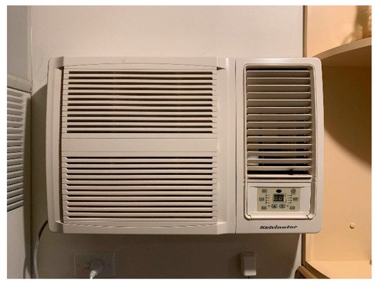
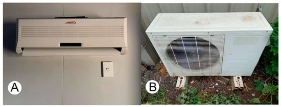
Figure 1. Wall-mounted direct expansion A/C. Source: First author.
Figure 2. Split systems air conditioner: (A) Indoor unit—Evaporator; (B) Outdoor unit—Condenser. Source: First author.
Other popular systems, used in heating only, are wall-mounted gas burners (Figure 3A) and completely ducted HVAC systems. It is not common to have both heating and cooling introduced within an HVAC ducted system. Further to these heating approaches, radiant panels, both hydronic and electric (Figure 3B,C), have recently become popular. Hydronic systems often apply a gas or diesel-fuelled boiler. It is important to note that these conditioning systems primarily condition occupants under the principle of convection [21,22][19][20]. In other words, they condition the air in a space.
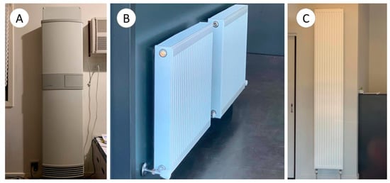
Figure 3. (A) A convective heater. (B) A hydronic radiator. (C) A modern hydronic radiator panel. Source: First author.
In the past and, again, more recently, residential buildings in Australia have applied electric floor heating (Figure 4). These systems use a mat of electric heating cable that runs underneath the finished floor, turning the floor into a thermally active surface that radiates heat.
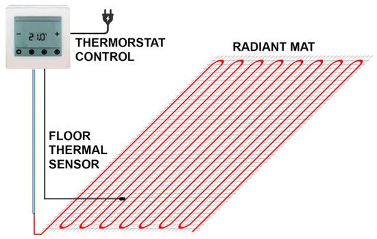
Figure 4. An electric floor heating system. Source: First author.
A radiant system mainly utilises the radiant heating transferring mechanism rather than air temperature conditioning. Heat can be radiated directly between the occupants and the radiant surfaces. Hydronic radiant systems use water as the heat transfer medium from the heat sources or sink to their radiant surfaces. A hydronic radiant system pumps hot or cold water through a series of pipes embedded inside or attached to the wall, floor, or ceiling [23][21] (Figure 5). This will turn the wall, floor, or ceiling surfaces into “thermally active surfaces” for radiating heat or absorbing heat [8]. The radiant surfaces will also have a heat conduction effect on the air in contact with them and thus promote convective heat transfer. For Australian housing, which mainly consists of separated houses [24][22], the commonly used heat sources can be a gas boiler or heat pump. Figure 5 shows a radiant heating and cooling system with a heat pump as the heat source and sink. Additionally, the heat pump can run on renewable energy technologies such as solar panels.
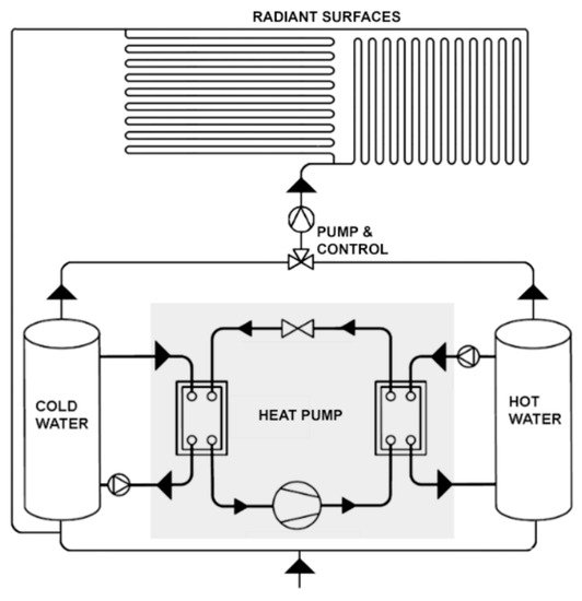
Figure 5. Radiant system diagram. Source: Fourth author.
The capillary tube mat is a recently introduced configuration of hydronic radiant systems. This type of radiant system has more flexibility, simplifies installation, and localises energy performance compared to HVAC systems or other types of radiators [25,26,27][23][24][25]. Radiant systems have become ubiquitous in Northeast Asia and Europe [23][21]. While, in the past, radiant systems were not yet widespread in North America, recently, the market for radiant systems in this region has shown rapid growth [23][21]. There has been no significant research on Australia’s radiant systems in the last few decades [18][26]. In general, radiant systems can be considered superior to convective systems, both in terms of thermal and energy performances [12]. Furthermore, Australian houses exhibit far more air leakage than European houses. This leakage’s effectiveness inherently jeopardises convective conditioning systems. Hence, the prospect of replacing conventional HVAC with radiant systems could lead to better thermal comfort and reduce energy costs.
3. Thermal Comfort
Thermal comfort can be defined as “the condition of the mind in which satisfaction is expressed with the thermal environment” [28][27]. However, several other definitions for thermal comfort have been pointed out and even debates around how thermal comfort can be defined [29][28]. The problem is that the mechanism of being “thermally comfortable” is highly complicated and affected by various factors, such as physiology, psychology, and behaviour [30][29]. Hence, several comfort models are used for different environments [31][30].
According to Fanger [32][31], thermal comfort can be quantitatively measured using six parameters, namely air velocity (Av), mean radiation temperature (MRT), air temperature (dry-bulb temperature—DB), air relative humidity (RH), metabolic rate (met), and clothing insulation (clo). Combining these parameters indicates thermal comfort in a controlled and conditioned environment. The level of thermal comfort (or discomfort) of a group of people is rated via predicted mean vote (PMV) index scaling from −3 (cold) to +3 (hot) [33][32]. Along with PMV, the index of the predicted percentage of dissatisfied (PPD) indicates the proportion of thermally dissatisfied people in the group. This principle makes up the classic PMV (Fanger) thermal comfort model shown in Figure 6.
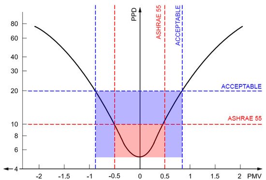
Figure 6. PMV—Fanger thermal comfort models. Source: Redrawn by the first author.
As the most classical thermal comfort model, the PMV thermal comfort model is commonly used in standards or guidelines such as ISO 7730, ASHRAE 55 (standard of The American Society of Heating, Refrigerating and Air-Conditioning Engineers) [28][27], or the REHVA (Federation of European Heating, Ventilation, and Air Conditioning Associations) Guidebook Number 7 [34][33]. The PMV thermal comfort model is well-suited and commonly used to assess thermal comfort in conditioned office spaces [35][34]. Loveday et al. [36][35] conducted an experiment proving that the PMV model accurately assesses thermal comfort in a radiant conditioned environment and concluded that a radiant conditioned space is similar to an air-conditioned space. According to ASHRAE 55, a thermal environment with an acceptable comfort level would have a PMV between −0.5 and +0.5, resulting in a PPD of less than 10% (Figure 6) [28][27]. However, the Fanger PMV comfort model can be considered conservative [37][36], and acquiring a PPD of less than 10% is not common [28][27]. Hence, the PPD of less than 20% (PMV between −0.8 and +0.8) is also welcomed as an acceptable level of thermal comfort (Figure 6) [28,37][27][36].
Mean Radiant Temperature (MRT)
MRT is a crucial parameter determining thermal comfort [14,28,38][14][27][37]. It is defined as “the uniform surface temperature of an imaginary black enclosure in which the radiation from the occupant equals the radiant heat transfer in the actual non-uniform enclosure” [39][38]. Stefan Boltzmann defined MRT as “a temperature value to evaluate the total radiation flux over the human body” [40][39]. MRT is the relationship between indoor surface temperature, direct and scattering solar radiation power, view factor toward transparent and translucent surfaces, and solar radiation receiving area of the occupant body [41][40]. MRT is the most complex parameter of thermal comfort, often difficult to control, calculate, and measure [41,42][40][41]. Yet, it is important to note that radiant systems function on the principle of MRT, not air temperature (dry-bulb). This is the crucial problem in radiative system control, which functions on the control principle of a thermostatic sensor (air temperature).
MRT was assumed to be equal to the air temperature in many early research papers in space conditioning [39,43,44][38][42][43]. However, this is not the case on many occasions, especially when solar heat gain is introduced [28,45][27][44]. In residential buildings, access to sunlight is a fundamental requirement. Thus, MRT will not be equal to the air temperature in residential buildings. Instead, MRT is a better index to represent occupants’ thermal sensation than air temperature [38,46][37][45]. Hence, in retrofitting residential buildings, MRT control should be prioritised.
Sui and Zhang [10] investigated the relationship between MRT and other thermal comfort parameters, namely air temperature, air velocity, and air humidity. The research proved the significant influence of MRT on thermal comfort. Sui and Zhang [10] illustrated that thermal comfort can be achieved even at high air temperatures with a low MRT. This allows the concept of high air temperature cooling and low air temperature heating to occur in a room. Air temperature and MRT are the two most critical aspects determining thermal comfort [34][33]. Radiant conditioning focuses on changing MRT via the internal surface temperature rather than changing the air temperature. Hence, cooling can be achieved even with high air temperatures, while heating can be provided with low air temperatures [34][33]. Additionally, Sui and Zhang [10] argued that, while a low air velocity means reductions in convection and evaporation, MRT can play a significant role to improve thermal comfort. Their research also indicated that the higher the humidity, the lower the MRT.
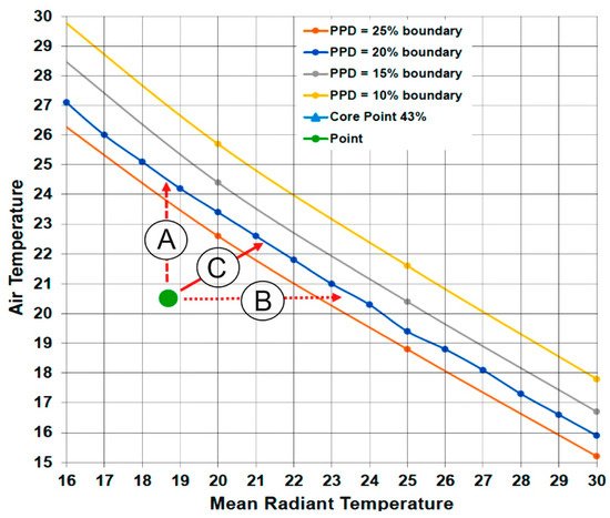
Figure 7 charts an investigation in achieving thermal comfort performed by Luther, Tokede, and Lui [37][36], applying similar principles as Sui and Zhang [10]. The circle and the triangle represent thermally unsatisfactory conditions, and there are three options to reach the acceptable level of thermal comfort (PPD = 20%). Option A raises the air temperature by about 3.5 °C, which can increase the conditioning energy cost by 30–45% [25][23]. Option B increases the MRT by 4.5–23.5 °C (for the circle) and provides heating while the air temperature remains at 20.5 °C. This can be achieved with the radiant surface’s temperature at 30–35 °C at a minimum cost [25][23]. Hence, the radiant system is more energy-efficient. Nevertheless, option C raises the air temperature and MRT, the shortest path, although the energy consumption will be higher than option B.
In a uniform air temperature environment, nonuniform MRT can cause thermal discomfort [36][35]. In turn, with uniform MRT, local thermal discomfort can be avoided even with high air temperature gradients [36][35]. Hence, MRT has more effect on human thermal comfort than the air temperature itself [47][46].
MRT can be calculated using the surface’s temperature and view factor (angle factor) between an occupant and internal surfaces. The equation is [48][47]:
where
Tr⁴ = T1⁴ × Fp−1 + T2⁴ × Fp−2 + … + TN⁴ × Fp−N
Tr = mean radiant temperature, K;
TN = surface temperature of surface N, K;
Fp−N = view factor (angle factor) between a person and surface N.
The view factor is the proportion of energy radiated from a surface and received by another surface [49][48]. The view factor represents the radiant heat exchanges between two surfaces [50][49]. The total view factor toward an occupant in a room equals 1 [34][33]. The view factor is affected by the surface shapes, angle, and distance between the two surfaces [49][48]. Hence, in thermal comfort, the view factor depends on the dimensions of the radiant surfaces and the distance to the occupant. The view factor for a person in a room also depends on the posture and position [51][50]. Although determining the view factor is highly complicated, two conventional methods of approximately determining the view factor’s value are the Fanger-Rizzo method and the Nusselt Analog method [52][51]. While the Fanger-Rizzo method is used in fundamental documents ASHRAE and the REHVA Handbook [34[33][47],48], the Nusselt method is not. This is an important factor in designing radiant systems for retrofitting residential buildings, especially where the systems can be mounted for maximum effectiveness.
4. Hydronic Radiant Systems
4.1. Types of Hydronic Radiant Systems
The Federation of European Heating, Ventilation, and Air Conditioning Associations (REHVA) Guidebook Number 7 classifies radiant conditioning systems into three types based on how the piping is installed [34][33]. Table 1 shows the three types of radiant systems, including:
| System Types | Schematic | Classify |
|---|---|---|
| Thermal active building system (TABS) | 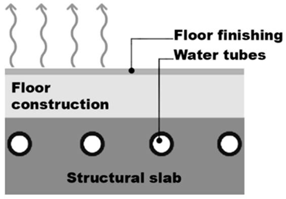 |
Heavyweight radiant system |
| Embedded surface system (ESS) | 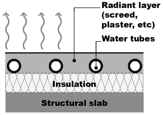 |
Medium-weight radiant system |
| Radiant panel (RP) | 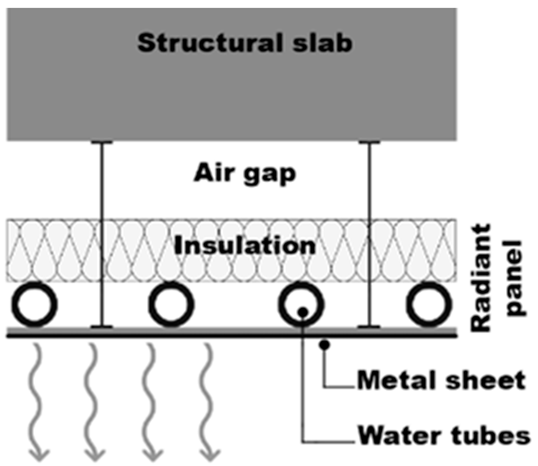 |
Lightweight radiant system |
-
Embedded surface system (ESS), with the tubing installed in a wall, floor, or ceiling layer but isolated from the main building structure.
-
Radiant panel (RP), where the tubing runs within prefabricated lightweight panels.
-
Thermal active building system (TABS), with the tube installed directly inside the building structure.
While the ESS and RP can be used in new constructions and retrofitting projects, TABS can only be used in new buildings. Two tube types are currently used in radiation systems, including small diameter tubes (metal or plastic tubes) and polyethylene capillary tube mats [53][52]. Hence, the standard ISO-11855 listed seven types of radiant systems [25][23]. In this category, the ESS is divided into four subtypes depending on the tubing position (type A–C), type F with a capillary tube, and type G with a wooden structure, while type E is identical to TABS.
Table 1 illustrates three different radiant hydronic systems. The thermal active building system (TABS) is the early radiant system that dates back to the 1930s [23][21]. It considers one substantial thermal mass that requires conditioning. This system can be relatively costly to run, as it stores a great deal of energy within the building fabric and is not reactive to sudden climate changes. TABS also does not show a specific insulation layer, and the hydronic tubing is located deep inside the structure. This results in potential thermal and energy performance reductions. Several research papers have revealed the problems of a heavy system design like TABS. As the sentinel load is stored and released by the thermal mass, the properties of the structure, such as thickness or thermal conductivity of the slab material, have a significant impact on the heat transfer process and thermal performance of this heavy system [54][53]. This heavy thermal mass results in a slow reaction time, potential overheating, and low energy efficiency [18][26]. While the thermal mass can be advantageous in maintaining the temperature of radiant surfaces, receiving an extra external load like solar heat gain can cause overheating or large temperature swings [55][54]. Heavy thermal mass can also reduce the efficiency of radiant conditioning systems, as energy is wasted when space is not occupied or wasted on a structure mass rather than contributing directly to the conditioning of the required environment [56][55]. In terms of reaction time, an experiment with radiant slab floor done by Merabtine et al. [57][56] showed that the system surface needs about 4 h to be heated up from 20 °C to 29 °C. Hence, this heavy system requires an advanced control system involving the water flow rate, inlet water temperature, and reaction time [18][26]. Additionally, the slow reaction time can increase the risk of condensation in the cooling mode if the space’s humidity increases faster than the system response [11].
In contrast to the thermal active building system (TABS), the embedded surface system (ESS) has smaller thermal mass components. The radiant hydronic tubes are isolated from the main structure mass and are closer to the room surface. The ESS is a lighter system than TABS, with less thermal mass resulting in lower thermal inertia [11], which means a faster reaction time and less energy waste. The system is also isolated from the main structure. The insulation layer is crucial in directing the heat transfer [11], preventing energy waste.
Finally, the radiant panel (RP) is the lightest, with the radiant hydronic tube wholly isolated from any considerable thermal mass. RP systems are relatively new and improved lightweight, reactive systems [11]. The panels can be integrated into a ceiling system [58][57], which allows concentration on conditioning the environment with the radiant tube isolated from a heavy thermal mass. Miriel et al. [11] experimented with a radiant cooling ceiling panel with metal tubes resulting in a low responsive time, although the time was not explicitly stated. The commonly used radiant ceiling has the top surface insulated, while the other, downward surface is used for heat transfer [13]. The insulation layer on top of the system can also consider acoustic absorption [11]. An experiment showed that a radiant panel system with tube mats had less than 15-min reaction times [53][52].
4.2. Radiant Panel Systems
Piping plays a critical role in radiant panel (RP) performance. The pipe diameter, space between pipes, and thermal resistance of the pipe material significantly impact the surface temperature of radiant systems [54][53]. Besides the water temperature, in heating, bigger pipes with low thermal resistance and less space between them result in higher surface temperatures [54][53]. In short, more tube surface area and less material thermal resistance mean better surface temperature and more efficient heat transfer. There are two main piping, including small-bore tubes (about ø20-mm metal or plastic tube) and polyethylene capillary tube mats used in RP systems. Zhao et al. [26][24] experimented on an embedded heating floor with a ø20-mm plastic tube and a capillary mat gypsum heating panel system. The results showed that the capillary mat system can provide thermal comfort with inlet water of about 8 °C lower and consume 45% less energy than panel systems with small-bore tubes. Additionally, the temperature difference between the inlet and outlet water in the capillary tube system and the small-bore tubes system is around 5 °C [26][24]. According to Miriel and Serres [11], polyethylene capillary tube mats provide flexibility in design and installation. Additionally, the distance between tubes and the heat resistance of the tubes and filling material in capillary tube radiant systems significantly influence the system’s thermal capacity [27][25]. Capillary radiant systems are also considered more flexible and responsive than metallic tubes, although the capillary tubes can encounter blockage due to the small tube diameter [11].
Consulting with our partner in the industry, KPW Solutions, the recommended water flow rated for normal radiant systems with small-bore tubes (usually ø20 mm) is 3–5 L/min for every circuit and will be higher for the capillary tube mat. Additionally, the water cycling rate for the system should be at least 40 times/h. This is necessary for ensuring uniform radiant surfaces.
Figure 8 shows a capillary radiant ceiling system being installed in a residential project in Victoria. The capillary mats are installed on the existing plasterboard ceiling (area A), and the top is covered using batt insulation (area B). The upper insulation ensures the downward stream of heat transfer, while the capillary tube enhances the thermal performance. The flexible and lightweight polyethylene capillary tube mat works well in this context of a confined and complex ceiling. The flexibility of the capillary mat allows installation with relative ease in various situations, making this type of piping ideal for retrofitting projects.
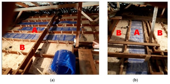
Figure 8. Capillary tube installation on a ceiling: (a) Capillary mats on existing plasterboard ceiling; (b) Batt insulation cover the top of Capillary mats. Source: KPW solutions.
Figure 9 shows an EES installed on a radiant floor system in a residential project in Victoria. The system’s section is shown in Figure 10. The capillary tube mats are utilised to reduce the response time that is negatively affected by the concrete screed and load-distributing layer needed for a solid floor system. Underneath the load-distributing layer is a solid insulation layer that prevents heat from reaching the structure mass directing heat to the top floor surface. The total thickness of this system is only 40–50 mm instead of the 120–150 mm of a thermally active building system (TABS).
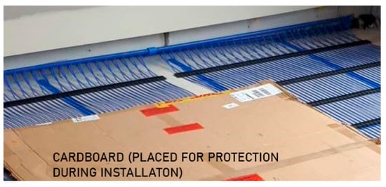
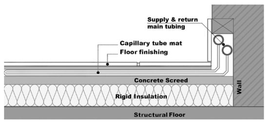
Figure 9. Capillary tube installation on a floor. Source: KPW Solutions.
Figure 10. Capillary tube radiant floor. Source: BEKA Klima-Komfort, redrawn by the first author.
4.3. A Prototype for a Lightweight and Dynamic Radiant Cooling System
Based on the lessons learned from the previous review, we propose an RP system with polyethylene capillary tube mats (Figure 11). Each panel has a capillary tube mat attached to a solid insulation board (Figure 11A). The insulation board has a layer of aluminium foil in contact with the capillary tube to increase the heat-directing effect (Figure 11B). The proposed finishing surface of a panel can be a perforated metal sheet or plasterboard that is in contact with the tube mat (Figure 11C). This finishing surface ensures the architectural appearance of the panel and the efficiency of radiant heat transfer. This lightweight and modular system integrates with the ceiling system (Figure 11D) or wall cover. This design focuses on solving two problems of radiant systems in retrofitting, non-modularity and system installation. Our system is lightweight, modular, and allows rapid system installation.
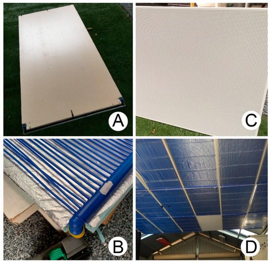
Figure 11. Capillary radiant panel system prototype: (A) Insulation board at the back; (B) Aluminium foil in contact with tube mat; (C) Perforated metal sheet at the front; (D) integrated into a ceiling panel. Source: First and second authors.
This prototype is currently under testing, indicating promising results. An initial demo heating operation was conducted. The water flow rate can reach about 14 L/min, leading to a 95 times/h water cycling rate. The system’s response time (from turning on to a stable surface temperature) is only about 15 min. However, we face a nonuniform surface temperature problem when the difference between the inlet and outlet water temperatures is too high (at about 20 °C). Due to limited data gathered from the initial test, further testing will be conducted
A diagram of the complete system components is shown in Figure 12. The design follows the principal diagram for the radiant system shown in Figure 5 and includes several pumping solutions to ensure adequate water flow, reduce the water leaks, and prevent blocking caused by air bubbles. The pressure tank is used to take the pressure changes in the system as the water temperature changes leading to changes in the water volume. The vacuum relief valves are used to trap the bubbles and prevent blocking. At the same time, these valves can release pressure if the water pressure in the system increases to a critical level. A pressure gauge is used for monitoring the water pressure. The system functions correctly without leaking if the pressure is stable between 1–3 Bar (14.5–43.5 psi).
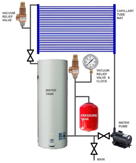
Figure 12. Capillary radiant panel system diagram. Source: KPW Solutions.
4.4. Mounting Position for Hydronic Radiant Systems
Sui and Zhang [10] claimed that a radiant cooling floor can provide the same level of thermal comfort as a radiant ceiling. Olesen [59][58] explained that having a radiant cooling system mounted on the floor can be more advantageous than the ceiling due to the close distance between a floor and the occupants, leading to a better view factor (angle factor). The view factor (angle factor) is a fundamental aspect of radiant heat transfer representing the radiant heat exchanges between two surfaces [50][49]. A better view factor means more efficient heat transfer.
Typically, the floor has the highest view factor compared to the wall and ceiling due to the close and uniform distance to the occupants (Figure 13A), resulting in the best heat exchange coefficient. Hence, the floor should be preferred. However, the efficiency of floor-mounting radiant systems can be obstructed by furniture or carpet covering the floor radiant surfaces [60][59]. Fontana [61][60] experimented with the impact of furniture coverage on the thermal performance of a radiant heating floor. The results showed that furniture can significantly impact the heat flux between a radiant floor and the subject environment, resulting in up to a 30% reduction in heat transfer. Hence, furniture coverage must be considered when designing radiant systems [61][60].
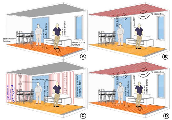
Figure 13. (A) Floor-mounted radiant systems; (B) Ceiling-mounted radiant systems; (C) Wall-mounted radiant systems; (D) Floor and Ceiling-mounted radiant systems. Source: First author.
It is claimed that the ceiling is the least-favourable mounting location for radiant systems [58][57]. The reason can be the usual long-distance from the system to the occupants, leading to low view factors. However, some clear advantages of a radiant ceiling can be seen, such as uniform MRT and not being obstructed by objects (Figure 13B). In fact, empirical results from a residential project indicated that a radiative ceiling, during cooling, kept the polished concrete floor cool within a 4-m floor-to-ceiling height. While this setup will not be advantageous for heating, it will still function and work with the assistance of air movement. Several research papers have suggested that the floor is not the optimal mounting position for radiant systems. Bojić et al. [58][57] compared the performance of radiant heating panels in four different positions. The results showed that, while mounting heating panels on the ceiling yielded the worst thermal performance, heating panels on both floor and ceiling was the best option for thermal comfort (Figure 13D), followed by a heating wall and floor. Karabay, Arıcı, and Sandık [60][59] conducted a similar experiment comparing a heating wall and floor, with the results also favouring a heating wall due to the better effect on room air temperature (Figure 13C) while not being affected by furniture coverage. Having said that, while conducting a design for radiant walls, we found that radiant wall systems can still be affected by furniture coverage, while doors and windows can render radiant walls unfeasible on some occasions. The distance between a radiant wall and the occupants can vary in terms of view factor (Figure 13C), leading to a nonuniform view factor and MRT. A question can be raised about how this nonuniform MRT can cause local thermal discomfort.
There are also debates on the effectiveness and efficiency of a heating ceiling and cooling floor. In fact, standard ISO 7730 shows that a heating ceiling can easily cause thermal discomfort [33][32]. Additionally, in EN 1264, the heat exchange coefficients of the heating ceiling and the cooling floor are similarly low, showing their limitation and ineffectiveness compared to other mounting positions [62][61]. However, as the heating ceiling and cooling floor are mentioned in standard ISO 7730, EN 1264, and the REHVA Handbook, it is still considered a viable option.
Overall, wall, ceiling, and floor-mounting radiant systems can provide adequate thermal comfort. This proves the feasibility of radiant system application. Although, in some buildings, it is not possible to install radiant panels at their preferred location, the radiant system with its flexibility can still be applied to other, less favourable locations and perform adequately.
5. Hydronic Radiant System Control
5.1. Instrumentation for Control
The study conducted by Sui and Zhang [10] showed the relationship between MRT and other measurable factors of thermal comfort and provided a basic mechanism in controlling radiant systems. Firstly, air temperature is not a significant factor, as a radiant system can provide cooling with a high air temperature and heating with a low air temperature [34][33]. Secondly, the lower the MRT, the lower the air velocity should be to maintain thermal comfort. However, it is not practical to reduce the air velocity to 0 m/s. Thirdly, the lower the MRT, the higher the humidity should be to maintain thermal comfort [10]. However, high air humidity increases the risk of condensation, which is the most problematic for radiant cooling systems. Interestingly, the recommended humidity for TABS in cooling mode is only 40% [34][33]. Hence, the principle of controlling a radiant system can be summarised by keeping the air velocity low, keeping the humidity in control, and, mainly, adjusting the MRT and adjusting the air temperature if necessary.
The flow rate of water and the temperature of the inlet water significantly impact the hydronic radiant system thermal performance [63][62]. In particular, a steady and fast flow rate will ensure a uniform heat flux on the radiant surface and better thermal performance, while the water temperature is the most vital aspect ensuring the thermal and energy performance of the system [64][63]. Hence, to properly function, the water flow rate should be fast enough to provide a uniform temperature across the radiant surfaces, while the water temperature needs to be adjusted to maintain thermal comfort and control the energy consumption appropriately. There are two flow rate control mechanisms: on–off and variable control speed. However, flow rate control faces several disadvantages, such as a nonuniform radiant surface temperature, high fluctuations in the room temperature, and even noise make it far inferior to the more precise temperature control [65][64]. Nevertheless, the flow rate control method can be used in an individual room via a simple on–off control system linked with a room thermostat [59][58]. Commonly used TABS radiant systems operate with a stable flow rate while adjusting the water temperature [66][65].
As the water temperature is the most critical aspect in controlling radiant systems, most of the proposed control strategies focus on optimising the water temperature supply to the spaces [65,66,67,68][64][65][66][67]. Olesen [69][68] pointed out that the set point for the water temperature (average of inlet and return water) needs to be adjusted based on the outside temperature and specific building type regarding mass, heat loss, and external and internal gain. The control mechanism recommended in the REHVA Handbook for central control is based on the average water temperature (between the inlet and returned water) [34][33]. The European standard UNE EN1264 and the REHVA Handbook dictate the maximum capacity of the radiant system in both cooling and heating (Table 2).
Table 2. Maximum capacity of radiant systems. Source: REHVA Handbook [34][33]. Source: Remade by the third author.
| Total Heat Exchange (W/m | 2 | K) | Acceptable Surface Temperature (°C) | Maximum Capacity (W/m | 2 | ) | ||||||||
|---|---|---|---|---|---|---|---|---|---|---|---|---|---|---|
| Heating | Cooling | Maximum Heating | Minimum Cooling | Heating | Cooling | |||||||||
| Floor occupied zone | 11 | 7 | 29 | 19 | 99 | 42 | ||||||||
| Floor perimeter zone | 11 | 7 | 35 | 19 | 165 | 42 | ||||||||
| Wall | 8 | 8 | ~40 | 17 | 160 | 72 | ||||||||
| Ceiling | 6 | 11 | ~27 | 17 | 42 | 99 | ||||||||
Valves control the flow rate and inlet water temperature in hydronic systems. For example, Miriel et al. [11] used a three-way valve to control the inlet water temperature for cooling and heating while keeping the flow rate stable. The valve control is still the primary control for even modern hydronic radiant systems [18,25,34][26][23][33]. A simple control mechanism used in early radiant systems is adjusting the inlet water temperature and flow rate via manual valve control [34][33]. Radiant systems can also be controlled automatically using the data provided by sensors [34][33]. These sensors collect the operative temperature data (MRT and air temperature) in a conditioned room and use the data on the control system and valves. The data on the inlet and return water temperatures and the mass flow rate allows the heat transfer between the system and the conditioned space to be calculated and controlled, resulting in improved thermal and energy performance [34][33].
While the traditional thermostat systems control the conditioning systems using dry-bulb temperature, the thermal comfort method applies the PMV index [70][69]. Meanwhile, controlling HVAC systems with only dry-bulb temperatures is inadequate and can benefit from PMV calculations [71][70]. As the radiant conditioned spaces are similar to air-conditioned spaces in terms of thermal comfort, a PMV calculation should be the controlling index for radiant systems [36][35].
Modern thermal imaging technologies can potentially aid in automatic control for radiant systems. Infrared thermal cameras can provide detailed data on the room surface temperatures and the location of heat sources [72][71]. Infrared thermal cameras allow data on MRT to be collected on a real-time basis and provide a precise calculation of the thermal comfort levels (PMV and PPD) [70][69]. This infrared thermal imaging can provide data to the control systems of HVACs, resulting in about a 0.4 °C difference in conditioned air temperature compared to traditional thermostat systems [70][69]. This can be equal to 3.2–4% cooling load savings. Zampetti, Arnesano, and Revel [71][70] also tested similar real-time thermal comfort monitoring systems to control heaters, resulting in 17% energy savings and better thermal comfort. Therefore, thermal imaging technologies, together with thermal comfort calculation methods, should be considered for hydronic radiant systems.
5.2. Problem with Thermal Mass and Controlling Strategy
The main aim of an optimal control strategy for the radiant systems is achieving peak thermal comfort and energy performance during operation [68][67]. This means maintaining an adequate level of thermal comfort when required while keeping energy consumption and operation costs low [34][33]. As some types of radiant systems are challenging to control and not reactive, the control strategy plays a more critical role in ensuring performance [56][55]. In this case, radiant systems with high thermal masses proved to be the most challenging [25,66][23][65]. The thermal mass can effectively reduce the peak conditioning load and close the gap between the day and night conditioning loads [73][72]. However, this also leads to a slow response time that challenges the system design and energy evaluation [74][73]. Therefore, high thermal mass radiant systems require efficient controlling strategies [66,68,73][65][67][72]. The REHVA Handbook recommends using two controlling levels for high thermal mass radiant systems, namely central and individual controls [34][33]. The room core air temperature to set the water temperature and individual control to adjust the flow rate in each room [34][33]. On the other hand, Raftery et al. [66][65] promoted zone control alone, as each thermal zone in a building may have different inlet water temperatures, average water temperatures, or flow rates.
The traditional control strategy for radiant systems is the continuous mode in which the heat flux between the system and the room is monitored, and the individual on–off control will respond accordingly to maintain a comfortable range of the room temperature [75][74]. However, this strategy has drawbacks, such as a slow response to the external environment and high risk of discomfort [75][74]. Hence, advanced control strategies were developed considering high thermal mass systems [74][73]. Romaní, de Gracia, and Cabeza [74][73] mentioned improved control strategies such as pulse width modulation, model predictive control, adaptive and predictive controls, and gain scheduling control. These advanced control strategies use data from weather forecasts or previous operations to set the control variables and parameters [74][73].
On the contrary, radiant systems with a low thermal mass, such as radiant panels, are more energy-efficient [34][33], more responsive, and easier to control and, hence, do not need a complex control strategy to properly function [25,74][23][73]. This is a significant advantage of radiant panels over other high thermal mass radiant systems. Nevertheless, an improved control strategy remains a viable option for retrofitting existing high thermal mass systems.
6. Radiant Cooling and Condensation Prevention
6.1. Radiant Cooling
The idea of hydronic radiant cooling systems has been developed and faces several difficulties. In the 1930s, Dr Oscar Faber successfully applied a cooling capability to a radiant floor system installed in the Bank of England building [23][21]. However, the early hydronic chilled ceiling system developed in the 1930s was unsuccessful due to the high condensation risk. Condensation remains one of the most significant problems of radiant cooling systems and prevented radiant cooling from being widely utilised for several decades [76][75]. Condensation can also reduce the air quality of a conditioned space and reduce the thermal efficiency of the radiant cooling systems [63][62]. Nevertheless, new knowledge and technology allow the problem to be avoided, allowing radiant cooling systems to be constantly improved. Hence, the interest in radiant cooling has recently returned, and radiant cooling systems have been used in several modern buildings, even in humid climates such as Singapore or Thailand [19][76].
As mentioned above, the condensation risk has been the biggest issue for radiant cooling systems from the very beginning in the 1930s [23][21]. Moreover, nearly 90 years later, Teitelbaum et al. [76][75] suggested that the condensation risk caused by the low surface temperature of the radiant surface is one of the main reasons preventing radiant cooling systems from being commonly used, especially in hot, humid climates. Morse [77] pointed out that the dew point temperature for condensation is high in this type of climate, while the radiant cooling surface must be operated at a low temperature to balance the high air temperature and humidity. However, condensation will occur if the temperature of the cooling surfaces is lower than the dew point. This makes setting up radiant cooling for hot, humid climates highly complicated. Additionally, the condensation risk for ceiling cooling is significantly higher than wall cooling or floor cooling [78], while ceiling cooling is the most common concept mentioned in radiant cooling research papers.
6.2. Preventing Condensation
Many studies have been conducted to solve this condensation problem of radiant cooling, focusing on hot, humid climates. The standard strategy is to combine radiant cooling with a mechanical ventilation system capable of dehumidification [17,79,80,81][17][79][80][81]. This method aims to reduce the relative humidity and dew point temperature, allowing radiant cooling to be operated at the required temperature. Some research papers have been conducted to improve the efficiency of dehumidification ventilation. For example, Binghooth and Zainal [80] and Hao et al. [17] used desiccant for dehumidification in ventilation systems to solve the problem in Malaysia’s hot, humid climate conditions, similar to Beijing, China. Both research papers concluded that condensation could be prevented, along with finding an energy-saving potential. Kim and Leibundgut [81] instead used hydraulic airbox units to reduce the moisture in the supply air, ending with good results.
In a conditioned environment, air humidity mostly comes from air infiltration, and when using dehumidification ventilation, it is essential to give the system enough time to reduce the interior air humidity [79,82][79][82]. Zhang and Niu [79] investigated the problem and recommended a strategy to prevent air infiltration and dehumidify the internal air at least one hour before the radiant cooling operation. Meanwhile, Ge, Xiao, and Wang [82] used a network of sensors and control systems to collect data on the outdoor air quality and calculated an optimal radiant cooling strategy. The resulted in a significant reduction in the dehumidification time to about half an hour.
Another approach to reducing the condensation risk is to prevent condensation droplets from forming using the material surface property. Yin and Wang [63][62] found that radiant cooling systems with gypsum surfaces have less condensation risks than metal and plastic surfaces. Tang et al. [83] looked at the condition of forming droplets on the surfaces of radiant cooling panels and proposed a superhydrophobic treatment to the radiant surface of the cooling ceiling. The result was that the condensation droplets become too small to be noticed. However, this method can only make condensation negligible rather than solving the problem.
Surprisingly, a breakthrough was made in the 1960s to tackle the condensation problem of radiant cooling in hot, humid climates [76][75]. Morse [77] proposed a radiant cooling system that could operate below the room dew point and make radiant cooling viable in hot, humid climates. The principle was to isolate the cooling panel within a high humidity environment while allowing material radiation to operate freely. The inventor used a sheet of polyethylene, a material transparent to radiation, to cover the cooling surface and isolate it from the high humid air. The result was a competent radiant system that had almost no impact on the air temperature or humidity. Hence, this system could be operated without any limitation on ventilation. Unfortunately, the principal did not receive much attention. After nearly half a century, Teitelbaum et al. [76][75] applied this principle to build a radiant cooling system prototype and conducted an instrumental experiment. A polyethylene membrane as the cover sheet material was used. The membrane allowed more than 80% of the radiation to pass by, ensuring the system’s thermal performance. The system was tested at an open-air bus stop in Singapore’s hot, humid climate and proved that thermal comfort could be achieved even with a high metabolic rate and with no condensation risk. The results also showed that the membrane-assisted radiant cooling system could be operated at temperatures below the dew point and could even be used in naturally ventilated environments.
6.3. Proposing a Design for a Condensation Resisted Radiant Panel System
Figure 14 illustrates a proposed cooling radiant panel (RP) system inspired by the design of Morse [76][75]. Figure 15 shows the components of the panel. The system utilises capillary tube mats to reduce the responding time and improve the thermal performance. The rigid insulation boards can provide a heat direction effect, as well as form the frame for the panel. The moulded aluminium sheet behaves like a radiant plate and enhances the heat direction effect. The panel is sealed by a membrane (EPDM, PP, or HDPE). This membrane allows most of the radiation from the environment to pass through and be absorbed by the tube mat and the aluminium sheet while isolating them from the environment. This design aims at providing a lightweight, dynamic, and condensation-resistant radiant panel system. This system is expected to be a solution for radiant cooling for retrofitting and new projects in hot, humid climates. In a future work, a prototype will be built and tested.
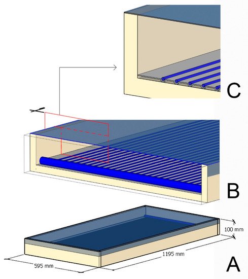
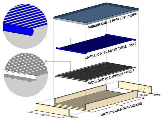
Figure 14. A condensation-resistant radiant cooling panel: (A) A complete panel and total dimensions; (B) Panel section; (C) Panel section detail. Source: First author.
Figure 15. Components of a condensation-resistant radiant cooling panel. Source: First author.
References
- Bulut, M.B.; Wilkinson, S.; Khan, A.; Jin, X.-H.; Lee, C.L. Thermal performance of retrofitted secondary glazed windows in residential buildings–two cases from Australia. Smart Sustain. Built Environ. 2021.
- Wilkinson, S.; Feitosa, R.C. Retrofitting housing with lightweight green roof technology in Sydney, Australia, and Rio de Janeiro, Brazil. Sustainability 2015, 7, 1081–1098.
- Ma, Z.; Cooper, P.; Daly, D.; Ledo, L. Existing building retrofits: Methodology and state-of-the-art. Energy Build. 2012, 55, 889–902.
- Jamil, H.; Alam, M.; Sanjayan, J.; Wilson, J. Investigation of PCM as retrofitting option to enhance occupant thermal comfort in a modern residential building. Energy Build. 2016, 133, 217–229.
- Goldsworthy, M. Towards a residential air-conditioner usage model for Australia. Energies 2017, 10, 1256.
- Simshauser, P.; Nelson, T. The outlook for residential electricity prices in Australia′s National Electricity Market in 2020. Electr. J. 2013, 26, 66–83.
- Willand, N.; Maller, C.; Ridley, I. Addressing health and equity in residential low carbon transitions–Insights from a pragmatic retrofit evaluation in Australia. Energy Res. Soc. Sci. 2019, 53, 68–84.
- Moe, K. Thermally Active Surfaces in Architecture; Princeton Architectural Press: New York, NY, USA, 2010.
- de Dear, R.; Zhang, F. Why the Perfect Office Temperature Is a Myth. Available online: https://www.sydney.edu.au/news-opinion/news/2019/03/14/why-the-perfect-office-temperature-is-a-myth.html (accessed on 20 July 2021).
- Sui, X.; Zhang, X. Analysis on combinations of indoor thermal microclimate parameters in radiant cooled residential buildings and drawing of new thermal comfort charts. Build. Serv. Eng. Res. Technol. 2016, 37, 66–84.
- Miriel, J.; Serres, L.; Trombe, A. Radiant ceiling panel heating–cooling systems: Experimental and simulated study of the performances, thermal comfort and energy consumptions. Appl. Therm. Eng. 2002, 22, 1861–1873.
- Karmann, C.; Schiavon, S.; Bauman, F. Thermal comfort in buildings using radiant vs. all-air systems: A critical literature review. Build. Environ. 2017, 111, 123–131.
- Serageldin, A.A.; Ye, M.; Radwan, A.; Sato, H.; Nagano, K. Numerical investigation of the thermal performance of a radiant ceiling cooling panel with segmented concave surfaces. J. Build. Eng. 2021, 42, 102450.
- Catalina, T.; Virgone, J.; Kuznik, F. Evaluation of thermal comfort using combined CFD and experimentation study in a test room equipped with a cooling ceiling. Build. Environ. 2009, 44, 1740–1750.
- Feustel, H.E.; Stetiu, C. Hydronic radiant cooling—Preliminary assessment. Energy Build. 1995, 22, 193–205.
- Imanari, T.; Omori, T.; Bogaki, K. Thermal comfort and energy consumption of the radiant ceiling panel system.: Comparison with the conventional all-air system. Energy Build. 1999, 30, 167–175.
- Hao, X.; Zhang, G.; Chen, Y.; Zou, S.; Moschandreas, D.J. A combined system of chilled ceiling, displacement ventilation and desiccant dehumidification. Build. Environ. 2007, 42, 3298–3308.
- Debnath, K.B.; Jenkins, D.P.; Patidar, S.; Peacock, A.D. Understanding residential occupant cooling behaviour through electricity consumption in warm-humid climate. Buildings 2020, 10, 78.
- Pedersen, T.H.; Hedegaard, R.E.; Kristensen, K.F.; Gadgaard, B.; Petersen, S. The effect of including hydronic radiator dynamics in model predictive control of space heating. Energy Build. 2019, 183, 772–784.
- Embaye, M.; Al-Dadah, R.; Mahmoud, S. Thermal performance of hydronic radiator with flow pulsation–Numerical investigation. Appl. Therm. Eng. 2015, 80, 109–117.
- Bean, R.; Olesen, B.W.; Kim, K.W. Part 2: History of radiant heating & cooling systems. Ashrae J. 2010, 52, 50.
- Australian Bureau of Statistics. Year Book Australia, 2009–10. Available online: https://www.abs.gov.au/AUSSTATS//Lookup/566B88038EED654CCA25773700169C79 (accessed on 10 December 2021).
- Feng, J.D. Design and Control of Hydronic Radiant Cooling Systems; University of California: Oakland, CA, USA, 2014.
- Zhao, M.; Kang, W.; Luo, X.; Yu, C.W.; Meng, X.; Gu, Z. Performance comparison of capillary mat radiant and floor radiant heating systems assisted by an air source heat pump in a residential building. Indoor Built Environ. 2017, 26, 1292–1304.
- Ding, P.; Li, Y.; Long, E.; Zhang, Y.; Liu, Q. Study on heating capacity and heat loss of capillary radiant floor heating systems. Appl. Therm. Eng. 2020, 165, 114618.
- Rhee, K.-N.; Kim, K.W. A 50 year review of basic and applied research in radiant heating and cooling systems for the built environment. Build. Environ. 2015, 91, 166–190.
- ASHRAE. ASHRAE Standard 55-2017: Thermal Environment Conditions for Human Occupancy; American Society of Heating, Refrigerating and Air Conditioning Engineers Inc.: Atlanta, GA, USA, 2017.
- Bessoudo, M.; Tzempelikos, A.; Athienitis, A.; Zmeureanu, R. Indoor thermal environmental conditions near glazed facades with shading devices–Part I: Experiments and building thermal model. Build. Environ. 2010, 45, 2506–2516.
- Anderson, T.; Luther, M. Designing for thermal comfort near a glazed exterior wall. Archit. Sci. Rev. 2012, 55, 186–195.
- Zhao, Q.; Lian, Z.; Lai, D. Thermal Comfort models and their developments: A review. Energy Built Environ. 2021, 2, 21–33.
- Fanger, P.O. Assessment of man′s thermal comfort in practice. Occup. Environ. Med. 1973, 30, 313–324.
- International Organization for Standardization. ISO 7730 2005-11-15 Ergonomics of the Thermal Environment: Analytical Determination and Interpretation of Thermal Comfort Using Calculation of the PMV and PPD Indices and Local Thermal Comfort Criteria; ISO: Geneva, Switzerland, 2005.
- Babiak, J.; Olesen, B.W.; Petras, D. Low Temperature Heating and High Temperature Cooling: REHVA GUIDEBOOK No 7; REHVA: Ixelles, Belgium, 2007.
- Fanger, P.O.; Toftum, J. Extension of the PMV model to non-air-conditioned buildings in warm climates. Energy Build. 2002, 34, 533–536.
- Loveday, D.; Parsons, K.; Taki, A.; Hodder, S. Displacement ventilation environments with chilled ceilings: Thermal comfort design within the context of the BS EN ISO7730 versus adaptive debate. Energy Build. 2002, 34, 573–579.
- Luther, M.; Tokede, O.; Liu, C. Applying a comfort model to building performance analysis. Archit. Sci. Rev. 2020, 63, 481–493.
- Hua Ge, P. An infrared sphere method to measure mean radiant temperature. ASHRAE Trans. 2013, 119, 1F.
- Chung, J.D.; Hong, H.; Yoo, H. Analysis on the impact of mean radiant temperature for the thermal comfort of underfloor air distribution systems. Energy Build. 2010, 42, 2353–2359.
- Chen, Y.-C.; Lin, T.-P.; Matzarakis, A. Comparison of mean radiant temperature from field experiment and modelling: A case study in Freiburg, Germany. Theor. Appl. Climatol. 2014, 118, 535–551.
- La Gennusa, M.; Nucara, A.; Rizzo, G.; Scaccianoce, G. The calculation of the mean radiant temperature of a subject exposed to the solar radiation—A generalised algorithm. Build. Environ. 2005, 40, 367–375.
- Kántor, N.; Unger, J. The most problematic variable in the course of human-biometeorological comfort assessment—The mean radiant temperature. Cent. Eur. J. Geosci. 2011, 3, 90–100.
- Walikewitz, N.; Jänicke, B.; Langner, M.; Meier, F.; Endlicher, W. The difference between the mean radiant temperature and the air temperature within indoor environments: A case study during summer conditions. Build. Environ. 2015, 84, 151–161.
- Chaudhuri, T.; Soh, Y.C.; Bose, S.; Xie, L.; Li, H. On assuming Mean Radiant Temperature equal to air temperature during PMV-based thermal comfort study in air-conditioned buildings. In Proceedings of the IECON 2016-42nd Annual Conference of the IEEE Industrial Electronics Society, Florence, Italy, 23–26 October 2016; pp. 7065–7070.
- Chaiyapinunt, S.; Phueakphongsuriya, B.; Mongkornsaksit, K.; Khomporn, N. Performance rating of glass windows and glass windows with films in aspect of thermal comfort and heat transmission. Energy Build. 2005, 37, 725–738.
- Alfano, F.R.d.A.; Dell’Isola, M.; Palella, B.I.; Riccio, G.; Russi, A. On the measurement of the mean radiant temperature and its influence on the indoor thermal environment assessment. Build. Environ. 2013, 63, 79–88.
- Barnaby, C.S.; Pedersen, C.O. Develop a Radiant System Module for the Simulation and Analysis of Spaces and Systems. ASHRAE Trans. 2015, 121, 364–374.
- ASHREA. ASHREA Handbook Fundamentals, SI ed.; American Society of Heating, Refrigerating and Air-Conditioning Engineers, Inc.: Atlanta, GA, USA, 2021.
- Vujičić, M.; Lavery, N.; Brown, S. View factor calculation using the Monte Carlo method and numerical sensitivity. Commun. Numer. Methods Eng. 2006, 22, 197–203.
- Lee, D.-S.; Kim, E.-J.; Cho, Y.-H.; Kang, J.-W.; Jo, J.-H. A field study on application of infrared thermography for estimating mean radiant temperatures in large stadiums. Energy Build. 2019, 202, 109360.
- Olesen, B.W. Thermal Comfort; Bruel & Kjaer: Nærum, Denmark, 1982; Volume 2.
- Guo, H.; Aviv, D.; Loyola, M.; Teitelbaum, E.; Houchois, N.; Meggers, F. On the understanding of the mean radiant temperature within both the indoor and outdoor environment, a critical review. Renew. Sustain. Energy Rev. 2020, 117, 109207.
- Díaz, N.F.; Cuevas, C. Testing and thermal modeling of radiant panels systems as commissioning tool. Energy Convers. Manag. 2010, 51, 2663–2677.
- Liu, Y.; Wang, D.; Liu, J. Study on heat transfer process for in-slab heating floor. Build. Environ. 2012, 54, 77–85.
- Athienitis, A.K. Investigation of thermal performance of a passive solar building with floor radiant heating. Sol. Energy 1997, 61, 337–345.
- Wang, Z.; Luo, M.; Geng, Y.; Lin, B.; Zhu, Y. A model to compare convective and radiant heating systems for intermittent space heating. Appl. Energy 2018, 215, 211–226.
- Merabtine, A.; Mokraoui, S.; Kheiri, A.; Dars, A.; Hawila, A.A.-w. Experimental and multidimensional numerical analysis of the thermal behavior of an anhydrite radiant slab floor heating system: A multi-objective sensitivity study. Energy Build. 2018, 174, 619–634.
- Bojić, M.; Cvetković, D.; Marjanović, V.; Blagojević, M.; Djordjević, Z. Performances of low temperature radiant heating systems. Energy Build. 2013, 61, 233–238.
- Olesen, B. Radiant floor cooling systems. Ashrae J. 2008, 50, 16–22.
- Karabay, H.; Arıcı, M.; Sandık, M. A numerical investigation of fluid flow and heat transfer inside a room for floor heating and wall heating systems. Energy Build. 2013, 67, 471–478.
- Fontana, L. Thermal performance of radiant heating floors in furnished enclosed spaces. Appl. Therm. Eng. 2011, 31, 1547–1555.
- BS EN 1264-5:2021. Water Based Surface Embedded Heating and Cooling Systems—Part 5: Determination of the Thermal Output for Wall and Ceiling Heating and for Floor, Wall and Ceiling Cooling; BSI Standards Limited: London, UK, 2021.
- Yin, Y.; Wang, R.; Zhai, X.; Ishugah, T. Experimental investigation on the heat transfer performance and water condensation phenomenon of radiant cooling panels. Build. Environ. 2014, 71, 15–23.
- Tye-Gingras, M.; Gosselin, L. Comfort and energy consumption of hydronic heating radiant ceilings and walls based on CFD analysis. Build. Environ. 2012, 54, 1–13.
- Ryu, S.-R.; Jae-Han, L.; Yeo, M.-S.; Kwang-Woo, K. A study on the control methods for radiant floor heating and cooling system in residential building. ASHRAE Trans. 2004, 110, 106.
- Raftery, P.; Duarte, C.; Schiavon, S.; Bauman, F. A New Control Strategy for High Thermal Mass Radiant Systems. 2017. Available online: https://escholarship.org/content/qt5tz4n92b/qt5tz4n92b.pdf (accessed on 8 October 2021).
- Karlsson, H.; Hagentoft, C.-E. Application of model based predictive control for water-based floor heating in low energy residential buildings. Build. Environ. 2011, 46, 556–569.
- Joe, J.; Karava, P. A model predictive control strategy to optimize the performance of radiant floor heating and cooling systems in office buildings. Appl. Energy 2019, 245, 65–77.
- Olesen, B.W. Radiant floor heating in theory and practice. ASHRAE J. 2002, 44, 19–26.
- Revel, G.; Arnesano, M.; Pietroni, F. An innovative low cost IR system for real-time measurement of human thermal comfort. In Proceedings of the IAQ2013 Conference, Vancouver, BC, Canada, 15–18 October 2013.
- Zampetti, L.; Arnesano, M.; Revel, G. Experimental testing of a system for the energy-efficient sub-zonal heating management in indoor environments based on PMV. Energy Build. 2018, 166, 229–238.
- Revel, G.; Sabbatini, E.; Arnesano, M. Development and experimental evaluation of a thermography measurement system for real-time monitoring of comfort and heat rate exchange in the built environment. Meas. Sci. Technol. 2012, 23, 035005.
- Lehmann, B.; Dorer, V.; Koschenz, M. Application range of thermally activated building systems tabs. Energy Build. 2007, 39, 593–598.
- Romaní, J.; de Gracia, A.; Cabeza, L.F. Simulation and control of thermally activated building systems (TABS). Energy Build. 2016, 127, 22–42.
- Cho, S.; Zaheer-Uddin, M. Predictive control of intermittently operated radiant floor heating systems. Energy Convers. Manag. 2003, 44, 1333–1342.
- Teitelbaum, E.; Chen, K.W.; Aviv, D.; Bradford, K.; Ruefenacht, L.; Sheppard, D.; Teitelbaum, M.; Meggers, F.; Pantelic, J.; Rysanek, A. Membrane-assisted radiant cooling for expanding thermal comfort zones globally without air conditioning. Proc. Natl. Acad. Sci. USA 2020, 117, 21162–21169.
- Rhee, K.-N.; Olesen, B.W.; Kim, K.W. Ten questions about radiant heating and cooling systems. Build. Environ. 2017, 112, 367–381.
- Morse, R. Radiant cooling. Archit. Sci. Rev. 1963, 6, 50–53.
- Tang, H.; Liu, X.-H.; Jiang, Y. Theoretical and experimental study of condensation rates on radiant cooling surfaces in humid air. Build. Environ. 2016, 97, 1–10.
- Zhang, L.; Niu, J. Indoor humidity behaviors associated with decoupled cooling in hot and humid climates. Build. Environ. 2003, 38, 99–107.
- Binghooth, A.; Zainal, Z. Performance of desiccant dehumidification with hydronic radiant cooling system in hot humid climates. Energy Build. 2012, 51, 1–5.
- Kim, M.K.; Leibundgut, H. Advanced Airbox cooling and dehumidification system connected with a chilled ceiling panel in series adapted to hot and humid climates. Energy Build. 2014, 85, 72–78.
- Ge, G.; Xiao, F.; Wang, S. Neural network based prediction method for preventing condensation in chilled ceiling systems. Energy Build. 2012, 45, 290–298.
- Tang, H.; Liu, X.-H.; Li, H.; Zhou, Y.; Jiang, Y. Study on the reduction of condensation risks on the radiant cooling ceiling with superhydrophobic treatment. Build. Environ. 2016, 100, 135–144.
More