Your browser does not fully support modern features. Please upgrade for a smoother experience.
Please note this is a comparison between Version 1 by Lazaros Aresti and Version 2 by Catherine Yang.
Waste heat recovery (WHR) has been a challenge for industries, as it can lead to energy savings, higher energy efficiency, and sustainability. WHR technologies are usually classified based on the output provided, namely heat recovery (HR) or heat-to-power (H2P) conversion.
- waste heat recovery
- WHR technologies
1. Flat Heat Pipes
Condensing economizers are a proven technology that can provide up to a 10% increase in boiler efficiency, provided that the exhaust is clean, such as that of natural gas burners. For example, radiant HEs for industrial applications have been proposed in the cement industry, but at LT. In this context, the I-ThERM’s HPHE and coatings provide new solutions to industry.
Several studies have been conducted to investigate the HPHEs for WHR, such as [1][2][3][4][31,32,33,34]. An experimental investigation of the HPHE in the I&S industry was conducted by Ma et al. [5][35]. The authors reported that the water-to-water HPHE was able to recover a heat-transfer rate from 6.37 kW to 7.36 kW or 129.24 W/(m2K) to 150.67 W/(m2K), respectively.
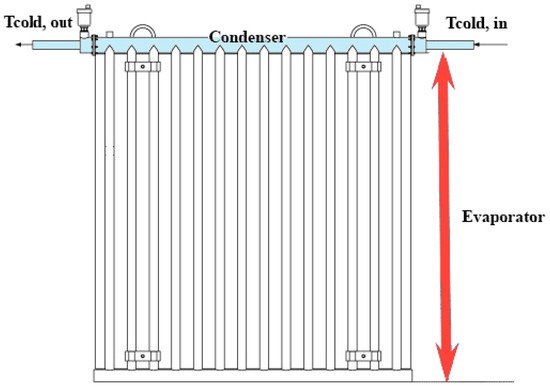
Heat pipes (HPs) are among the most popular passive heat-transfer technologies. Important parameters to determine the efficiency of an HP are the choices of the working fluid and casing material [6][36]. Heat pipes have a broad range of usage, from LT cryogenic applications to HT applications, in which efficient heat transfer is required. Thus, an HP can be used in a variety of applications, such as nuclear and LT applications. Low-temperature applications include industrial sectors such as pharmaceutical, food processing, and biotechnology, as well as chemical and medical industries. Although HP technology is very promising and efficient for many applications in industry, there are still factors to consider, such as cost and technology development. Compared to conventional heat-transfer methods, HPs have a higher initial cost. HPs are in general cylindrical, although the evaporator or condenser can also be flat; in such a case, they are called flat HPs. Compared to conventional cylindrical HPs, FHPs (Figure 12) have important advantages associated with their isothermal characteristics and flat evaporator surface, which maximizes the radiation absorbing area. FHP WHR systems constitute a new innovation (UK patent application Nos. 1,410,924.3 and 1,410,933.4). Their innovation potential is quite significant, as there are currently no such systems on the market.
Clearly, FHPs have the same benefits as conventional HPs, but due to their geometry, they can be used in specific applications more efficiently. For example, the combination of flat pipes and photovoltaic thermal (PV/T) panels was a successful combination, as stated by Jouhara et al. [7][37], as this could reduce the manufacturing costs and increase the viability of mass production. The choice of working fluid and material for the HP can enable FHP systems to absorb or reject heat in a particularly wide range of temperatures, from below 0 °C to above 1000 °C.

Not many studies on FHPs are available in the literature. Jouhara et al. [8][38] designed and manufactured an FHP capable of recovering heat by thermal radiation from sources at temperatures higher than that of the surface of the HPs. The overall dimensions of the flat HPHE were 1 m high and 1 m wide. The HPHE consisted of 14 stainless steel pipes connected by a header at the bottom and a tube HE at the top. The prototype was tested in a laboratory conditions, as well as in an industrial steel process. It was concluded that FHPs were promising for WHR in the steel industry, but there were also some challenges needing further investigation. In addition, Jouhara et al. [9][39] developed and validated a novel PV/T system, called a “heat mat”, which was based on FHP and operated as a building envelope. The effects of cooling cycles on the temperature and electrical output of the FHP PV/T panels were experimentally examined. It turned out that the temperature of the panels decreased from 40–58 °C to 28–33 °C, while the electrical efficiency increased by 15% with the use of an active cooling cycle in the panels. Moreover, the thermal efficiencies of the heat mat with and without the PV layer were 50% and 64%, respectively.
FHPs can be used for heat recovery from LT and MT sources. FHPs that can be manufactured in different configurations can also be used for first-stage heat recovery from HT exhausts. They can also be used for temperature control of spaces and liquid baths. Flat HPs with the right choice of materials and working fluid can be able to recover heat primarily by radiation, but also by convection at temperatures > 200 °C, and they use this heat for power generation through the sCO2 cycle.
2. Heat-Pipe Condensing Economizers
There are different types of HEs for different applications but with similar functionality, such as finned tubes, coiled tubes, and condensing and noncondensing economizers. The latter two are mainly used to increase the efficiency of boiler systems. Boilers equipped with condensing economizers (CEs) can reach overall efficiencies exceeding 90%. A CE, by reducing the flue gas temperature below its dew point, can cause the overall heat recovery and the steam system efficiency to increase by up to 10%, leading to an improved WHR effectiveness.
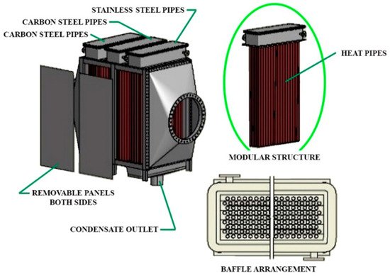
Condensing economizers (Figure 23) provide new WHR prospects due to their very high heat-transfer coefficient, large heat-transfer surface area, and low drop in gas side pressure. There are two types of CEs: those of indirect and those of direct contact. Indirect-contact CEs remove heat from the hot gases by passing them through HEs. Direct-contact CEs offer high heat transfer through water recovery capability, as the heated water can be collected for boiler feed water, space heating, and/or plant process needs. The recovered water is acidic, requiring treatment before use such as membrane technology, external heat exchange, and/or pH control.

Figure 23.
Schematic representation of a condensing economizer.
The standardized designs based on HPs for WHR from gaseous exhausts have the following capabilities: (a) they allow easy application with minimal process interruption; (b) they require minimum space; (c) they require minimum heat-transfer area due to the two-phase heat-transfer capability of HPs; (d) they allow maximum heat recovery through condensation by an appropriate selection of materials and coatings; and (e) they provide easy cleaning and reliable and minimum maintenance operation.
Similar to FHPs, innovations in this area also include exploring and determining optimal material coatings and HP fluids for different temperature ranges, approaches to improving the primary (exhaust/process) fluid heat-transfer coefficient for the different temperature ranges, and a tool for designing and determining condensing HPs.
There are two ways to recover the waste heat from boiler flue gases. Conventional economizers preheat the boiler make-up or feed water. CEs recover both latent and sensible heat from the flue gas, thereby increasing boiler efficiencies to more than 90%. Heat pipe CEs can be installed in harsh environments, exhibiting high resistance to corrosion and acidic gases. These HPCEs could gain a major advantage over the conventional CEs and gas boilers as optimum material coatings and HP fluids are developed for different approaches to improve the primary (exhaust/process) fluid heat-transfer coefficient for different temperature ranges. Design criteria for CEs coatings can also be found in [10][11][40,41], in which a comparison between film-wise and drop-wise condensation related to corrosion and an increase in the heat-transfer rate was presented.
Condensing and noncondensing HPs (economizers) can be used to efficiently recover heat from exhausts and use this heat to generate power through the sCO2 cycle at temperatures as low as 200 °C. Below 200 °C, the TFC can be employed (see below). Where liquid waste streams are available at suitable temperatures below 100 °C, standard HEs (plate, shell-and-tube, etc.) can be employed.
3. Trilateral Flush Cycle
Regarding H2P systems, ORCs have become a mature technology adopted in industrial environments. ORC units are commercially available at small (0.5–100 kWe) and large scales (1–20 MWe), with economies of scale that reduce the capital costs of the heat to power block from EUR 9000/kWe to EUR 3000/kWe. ORC systems have been adopted mainly in applications with a temperature range between 100 °C and 300 °C. As such, the high-grade waste heat potential that is typical of the I&S, aluminum, glass, and cement industries has not been fully exploited yet. The same applies to LT heat sources that, for instance, characterize the food or paper sectors. Based on the case studies analyzed, I-ThERM’s TFC and sCO2 could provide substantial advantages compared to ORC technology, in terms of efficiency, footprint, power flexibility, and the use of environmentally friendly working fluids.
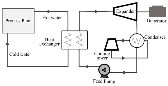
The TFC is a thermodynamic power cycle with its expansion starting from the saturated liquid state rather than from a vapor phase (see Figure 34). In the absence of a boiling part, heat transfer from the heat source to the working fluid (liquid) is realized due to good temperature matching. Compared to an equivalent steam ORC system, the TFC has a twice as high power-recovery potential [12][42]. Moreover, TFC can operate with no need for an extra cooling tower/heat rejection system, where heat in the waste stream is rejected. The TFC has been under consideration for more than 30 years, but the low efficiency of expander technology and the high pump power have hindered its development up to commercialization.

Figure 34.
Schematic representation of the trilateral flush cycle.
The efficiency of the system also depends on the efficiency of the two-phase expansion process; this has been the main obstacle in the development of the TFC cycle up to the commercialization stage. Another problem is the relatively high pump power, which limits the net electrical power available from the system. Studies and laboratory investigations have shown, however, that adiabatic expansion efficiencies of more than 70% can be achieved [13][14][43,44].
The proposed TFC systems can be compared to conventional ORC units installed in LT/MT (70–200 °C) industrial processes. An important development beyond the state of the art is the thermally driven compression system, which can replace the pump in the TFC cycle. This can reduce the parasitic losses of the cycle and improve the overall thermal efficiency. Thus, the proposed TFC units can replace the conventional ORC units working with MT gases.
A small-capacity TFC system with 5 kW electrical power output was developed and tested by Spirax Sarco at its Cheltenham, UK, facilities. This system used the thermal energy from the waste stream to provide the pumping energy for the cycle, thus overcoming the disadvantage of the high pumping power of TFCs. This should make the TFC an attractive system for power generation from LT heat sources as low as 70 °C. Optimizing turbine steam expanders, already developed by Spirax Sarco for low-capacity steam power systems to operate efficiently at the necessary heat source LTs system, will increase heat recovery.
4. Supercritical Carbon Dioxide Cycle
In recent years, there has been considerable research and development of ORC systems, and a number of manufacturers are currently researching systems for a range of applications. While the current state of the art shows maturity for the first generation of ORC systems, with typical efficiencies of 6% to 16%, there is still room for further research and development to increase efficiencies to 20% [15][29].
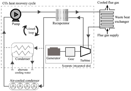
A technology that has the potential to provide higher thermal energy conversion efficiency compared to ORC is the supercritical CO2 Brayton Cycle system (sCO2), illustrated in Figure 45.

Figure 45.
Schematic representation of the supercritical carbon dioxide cycle.
Supercritical CO2, operating in a similar manner to other turbine cycles, uses carbon dioxide as working fluid. CO2, unlike other working fluids, undergoes radical density changes over small temperature and pressure ranges; this allows large amounts of energy to be extracted at HT using relatively small-sized equipment, of a smaller size than steam or gas turbines. It has been demonstrated through modeling and laboratory studies that the sCO2 cycle can provide, depending on operating pressures and temperatures, an energy-conversion efficiency of 30% [16][45].
According to Ahn et al. [17][46], the sCO2 Brayton Cycle has gained much attention for application in next-generation nuclear reactors. The authors reported that this cycle has a great potential to be used for WHR as well.
Supercritical CO2 cycle systems are under research and development by major power system manufacturers such as Mitsubishi Electric, Siemens, etc. A large, 7.5 MWe system, the Echogen EPS100, is under research and development for large industrial fuel-fired processes, utility-scale power generation, and concentrated-solar thermal utility applications.
However, a small modular sCO2 power system could be easily employed for a variety of HT H2P applications. The sCO2 cycle is of a size 10 to 100 times smaller than the Rankine cycle, with its efficiency exceeding 30%, and has a working fluid (CO2) with good properties; CO2 is nonflammable and nontoxic, and has a global warming potential of 1. Similar to TFC systems, sCO2 units can be compared to conventional ORC units installed in HT (200–500 °C) industrial processes.
A 5 kW CO2 cycle system was developed by Enogia (Enogia, Marseille—France) and installed in a specially designed test facility at Brunel University London for further testing and development of a 50 kWe system for power generation using WHR from a biomass boiler.
5. Potential Market and Performance of the “New” Technologies
The main industrial sectors for the application of the “new” technology solutions are: (i) most industrial sectors with H2P generation—heat source temperatures of 70–200 °C; (ii) sectors with heat-to-power generation—exhaust temperatures of 200–500 °C, such as cement, ceramics, food and drink, metals, paper and pulp, etc.; and (iii) sectors with temperatures up to 500 °C, such as metal and petrochemical.
In order to assess the potential of the above-mentioned technologies in the EU market, it should be noted that, as already mentioned, the TFC and sCO2 systems were assessed in the ORC market, and the HPCE systems in the corresponding CE market. These can be found in the literature; for example, [18][19][20][21][4,6,9,10].
In terms of FHP technology, the potential market can be assessed by identifying the industrial processes in which FHP could be used. As mentioned above, an FHP system is designed for heat recovery mostly by thermal radiation from sources at temperatures higher than that of the surface of the HPs. The FHP outer surface absorbs the radiation heat and transfers it through the HP evaporator wall by conduction to the inner surface. Once the working fluid attains the saturation temperature, it evaporates and flows upward to the condenser. Then, through a shell-and-tube HE system, the heat is transferred to the cooling fluid, which condenses the working fluid. Finally, the condensate flows back to the evaporator section under gravity. Installation of FHP panels requires industrial processes to have radiant heat sources with temperatures higher than the surface temperature of the HPs, and open spaces near these processes for the installation of FHP panels to recover the radiant heat. There is plentiful industrial manufacturing with HT processes and wasted heat, but using the FHP system requires two basic conditions: (i) the heat must be transferred by thermal radiation; and (ii) the existence of open space near the radiant source for the panels’ installation. The I&S industry turned out to be the best option for using HP systems, owing to the large amount of the radiant waste heat produced during the casting, rolling, and cooling processes in the formation of products. In particular, FHPs could be used in the wire rod process—a very common process in the I&S industry—to recover radiant heat from the cooling/rolling stage from the wire rod mill, where the hot wire rope moves after the casting machine.
A very detailed analysis can be found in [18][4]. The expected performance of the above technologies compared to the baseline technologies in relation to potential PBPs is shown in Table 1.
| FHPS | HPCE | TFC | sCO | 2 |
|---|---|---|---|---|
| Temperature range (°C) | 0–1000 (depends on the material of the FHPS and the fluid used in the HPs) | Exhaust gas temperature from combustion 200–500 | 70–120 | 300–500 |
| State-of-the-art competing technology | None | Bespoke condensing economizers for industrial process exhausts (200–500 °C) | ORC | ORC (at 300 °C) |
| Potential efficiency | Up to 75% (depends on many design parameters, in particular the temperature of the heat source, the size of the FHPS—the largest the size the higher the quantity of heat that can be recovered and the higher the cost) | Heat-recovery effectiveness sensible 78%, latent 36% (for a designed 200 kWth HPCE) | 6–10% | 16–20% |
| Conventional system efficiency |
N/A | Heat-recovery effectiveness similar to HPCE, sensible 78%, latent 36% (conventional economizers can be designed to provide similar heat-recovery effectiveness as the HPCE) | 5–8% (this is an estimate for LT heat-to-power conversion) | 10% |
| Installed cost per power output | EUR 300/kWth (depends largely on infrastructure necessary for the installation of the technology and the utilization of the heat recovered; for a 200 kWth unit, it is estimated that installed cost will be approximately EUR 250/kWth) | EUR 250/kWth | Estimated at EUR 2000–2500/kWe | EUR 6000/kWe (for a proof-of-concept system; for large-capacity systems, the cost will be much lower) |
| Conventional system cost per power output | N/A | Similar costs to HPCE, EUR 150/kWth (cost assumed to be equivalent to HPCE, although HPCE offers additional advantages such as a potential smaller size and lower maintenance costs) | EUR 2000/kWe | EUR 2000/kWe |
| Heat recovery/Power output | 200 kWth (value of thermal output specified for I-ThERM) | 200 kWth | 100 kWe | 50 kWe |
| Energy saved per annum (KWh) | 1,750,000 | 1,750,000 | 876,000 | 438,000 |
| Cost savings (EUR) | 70,000 (for a EUR 0.04/kWh price of natural gas) | 70,000 (for a EUR 0.04/kWh price of natural gas) | 105,120 (for a EUR 0.12/kWh price of electricity) | 52,560 (for a EUR 0.12/kWh price of electricity) |
| Installed cost of technology (EUR) |
60,000 | 50,000 | 250,000 | 300,000 |
| Payback period (PBP) (years) |
0.9 | 0.7 | 2.4 | 5.7 (PBP is long due to the small power output of the pilot system) |
Summing up, the benefits from such implementations of the “new” technologies are: (i) a reduction in the parasitic losses of the cycle and improvement of the overall thermal efficiency with the TFC system; (ii) the principles of this innovation can also be applied to other power systems such as ORC cycles; (iii) small capacity range, up to 100 kW (sCO2 system); (iv) can absorb/reject heat over a very wide temperature range, from below 0 °C to above 1000 °C (with the use of the FHP systems); (v) can improve the primary (exhaust/process) fluid heat-transfer coefficient in different temperature ranges and increase the quantity of recovered heat (HPCE systems). In addition, regarding space requirements, as mentioned above, the HPs for FHPs and HPCEs can lead to minimization of the relevant heat-transfer area and space. In general, the space requirement matter for the use of certain technologies (including TFC and sCO2, comparable to ORC) is of course dependent on the space characteristics of each application site.
