Additive manufacturing technologies, well known as three-dimensional printing (3DP) technologies, have been applied in many industrial fields, including aerospace, automobiles, shipbuilding, civil engineering and nuclear power. However, despite the high material utilization and the ability to rapidly construct complex shaped structures of 3D printing technologies, the application of additive manufacturing technologies in railway track infrastructure is still at the exploratory stage.
- 3D printing
- additive manufacturing
- railway track
- railway infrastructure
1. Introduction
2. Additive Manufacturing in Railway Components
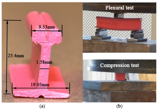
2.1. Rails
| Reference | Base Material of Powders | Powder Type |
|---|---|---|
| Lai et al. (2019) [40] | Fe-based | 410L, 420SS |
| Co-based | Stellite 6, Stellite 21 | |
| Lu et al. (2019) [66] | Fe-based | martensitic stainless steel (MSS) |
| Roy et al. (2018–2020) [55][56][57][58][59][60][61][62][63][64][65][66][67][55,56,57,58,59,60,61,62,63,64,65,66,67] | Fe-based | 410L, 420SS |
| Co-based | Stellite 6 | |
| Fu et al. (2015) [43] | Fe-based | martensitic stainless steel (MSS) |
| Zhu et al. (2019) [68] | Fe-based | 316L, 410L, 420L |
| Lewis et al. (2015–2017) [52][69][70][52,69,70] | Fe-based | Hadfield, martensitic stainless steel (MSS), 316 Stainless |
| Co-based | Stellite 6 | |
| Narayanan et al. (2019) [71] | Fe-based | a premium martensitic stainless steel |
| Meng et al. (2019) [50][57][50,57] | Ni-based | Not mentioned |
| Wang et al. (2017–2018) [35][36][53][35,36,53] | Fe-based | AISI316L stainless steel produced by Höganäs |
| Seo et al. (2019) [12] | Co-based | Stellite 21 |
| Ni-based | Inconel 625, Hastelloy C | |
| Clare et al. (2012) [47] | Ni-based | Stellite 6 |
| Guo et al. (2015) [24] | Co-based | Not mentioned |
| Wang et al. (2014) [48] | Co-based | Not mentioned |
| Aladesanmi et al. (2019) [72] | Others | Ti, TiB2 |
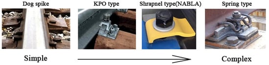
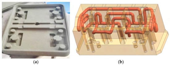
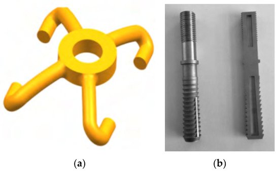
2.2. Fasteners
2.3. Sleepers
2.4. Supporting Layers
2.5. Special Components
3. Challenges
Even though additive manufacturing technologies have many advantages and have been applied in some civil buildings and lightweight structures for aerospace fields, the application of 3D printing in railway engineering is still in the explosion stage. This is due to the limitations as follows.
3.1. Reliability
The materials used for 3D printing can be classified into three main types, including polymer materials (e.g., photosensitive resin, thermoplastic polymer and hydrogels), metallic materials(e.g., Fe-based, Ti-based, Co-based, Cu-based alloys and etc.) and ceramic materials(e.g., cement materials, clay materials and silicate glass materials)[135][136]. Even though those materials can be 3D printed in complex shapes by different additive manufacturing processes, the mechanical properties of many 3D printed samples are usually less than casting samples due to the error in the 3D printing process[137]. Conventional railway track infrastructure is of simple geometric shapes and can be produced easily with well-developed conventional railway construction methods.
Moreover, many additive manufacturing technology processes include heating(melting) and cooling processes, which result in uneven deformation and residual stress inside the 3D printed samples. Other printing processes may also produce defects in 3D printed samples, such as small voids (bubbles) and microcracks. These defects will decrease the strength and life cycle of printed samples. The mechanical performance of 3D printed samples is greatly affected by printing speed, printing orientation, printing temperature, etc.[138]. However, there is no specific standards for 3D printing samples to ensure the 3D printed sample quality. This uncertainty of 3D printed samples hinders the use of 3D printing technology in railway engineering fields. Many 3D printed samples have rough surfaces due to the poorer accuracy than casting mould methods [136]. When additive manufacturing technology is adopted to produce an enhanced layer on the top of rails, grinding and polishing processes are compulsory for making a smooth surface. These processes are time-consuming.
Most importantly, the railway track infrastructure is required to have good fatigue performance under long-term moving train loads[139]. Most 3D printed samples are tested under static and quasi-static loads; the behaviours of 3D printed samples under dynamic loads and long-term loads have not been fully understood yet, which may result in the risk of failure of the railway system under long-term service.
In general, the risk in reliability of 3D printing components in railway engineering is caused by poor raw material properties and 3D printing defects. The development of 3D printable materials, technologies and standards will gradually solve the reliability problems of 3D printing in railway track infrastructures.
3.2. Size and Space Limitation
The size limitations of different 3D printing technologies are different. The maximum size of 3D printed metallic, and polymer samples are usually less than 1 m, which is limited by the size of 3D printing machines. The length of railway sleepers is 2.6 m, and the width of ballast beds and slab tracks are more than 2.6 m[102]. It is not easy to use 3D printing to manufacture all-in-one large-size composite sleepers or track supporting.
3D printing concrete technology allows large size 3D printed constructions, such as 3D printed civil buildings and bridges, but the printing equipment (e.g., robotic arm and removable tracks) needs to be put on-site[140][141]. The land areas of 3D printed houses and bridges are in the order of hundreds of square meters, and the construction site is mostly located in downtown areas on plate ground. Unlike these infrastructures, the length of railway lines is much greater, and much railway infrastructure is located on mountain tunnels, underground tunnels, bridges, and in open suburbs. The field conditions make the preparation and placement of 3D printing machines difficult.
3.3. Cost
The qualitative comparison of the average cost of fabricating products between 3D printing technology and conventional manufacturing technology is present in Figure 15. The average cost of products fabricated using conventional subtractive manufacturing methods (e.g., CNC) increases when the product complexity increases or when the product quantity decreases. This is because manufacturing products with complex shapes by subtractive technology needs complicated processes (e.g., cutting, drilling and milling). The average cost of 3D printing technologies is not sensitive to product complexity and quantity. Thus, 3D printing technologies show excellent prospects for a small quantity of complex products. However, the geometric shape of railway track infrastructure components is simple, and the demand for railway components for constructing a railway line is massive. This means that using conventional subtractive manufacturing technologies to build railway infrastructures is cheaper than 3D printing technologies, which hinders 3D printing in railway infrastructures.
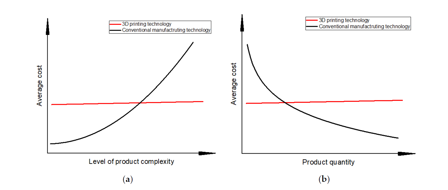
Figure 15. Qualitative comparison of costs between 3D printing technology and conventional manufacturing technology. (a) cost of the level of product complexity; (b) cost of the product quantity.
4. Perspectives
Based on the previous study, the highlight findings and the knowledge gap of 3D printing application in railway track infrastructures can be described well in Table 2.
Table 2. Summary of 3D printing application and research in railway track infrastructure.
|
Components |
Highlight Finding |
Knowledge Gap |
|
Rails |
3D printing technologies can be used to repair and enhance rails by generating an enhanced layer on the railhead area. The hardness and fatigue performance can be improved. The failure modes of 3D printed composite rails will change when the fiber contents changes. |
No study uses 3D printing technologies to fabricate a full rail with metallic materials. Also, the mechanical properties of 3D printed composite rails are poor. The 3D printing technologies about metallic materials still need to be improved. The future study can produce a full rail with metals and improve the mechanical properties of 3D printed composite rail by adding different materials with high strength. |
|
Fasteners |
3D printing can reduce the fabricating time of steel plates by mould optimization. 3D printing allows the production of structures with complex geometric shapes. |
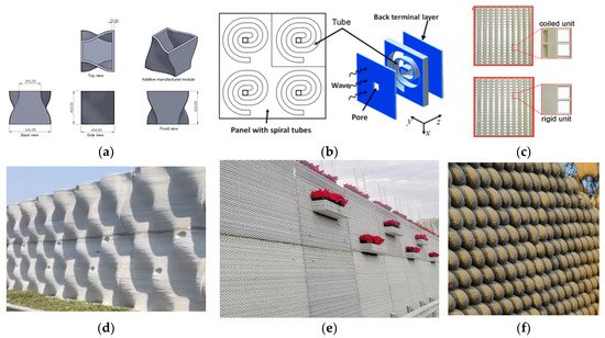
There is no fastener component directly fabricated using 3D printing. The clips and the rail pads can be designed and produced with smart shape and high damping porous structures such as honeycomb, lattice and TPMS structures. |
|
Sleepers (bearers) |
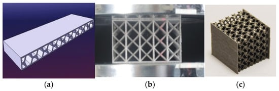
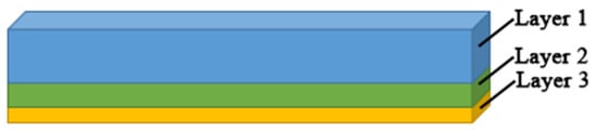
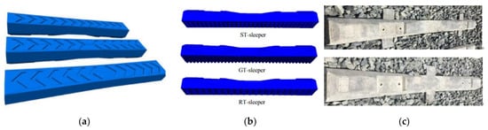
Composite sleepers (bearers) can be produced with multiply layers using 3D printing technologies. The shape of sleepers(bearers) can be optimised for saving materials and improving track performance. |
The research about combining different materials in composite sleepers (bearers) is limited, and the shapes of sleepers (bearers) are simple. Future research can try 3D printed sleepers (bearers) with multi-materials, multi-layers and optimised shapes. |
|
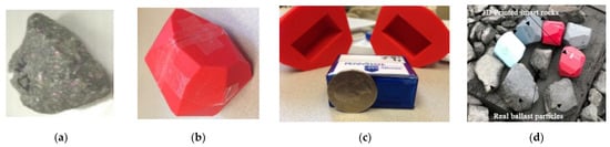
Supporting layers |
3D printed smart rocks with internal sensors can help detect the dynamic responses of ballast particles in the ballasted track on sites. 3D printing concrete technologies can be used to construct concrete slabs. |
There are limited studies about designing 3D printable one-in-all track support. The research about 3D printed track supports with smart structures can be carried out. |
|
Special components |
3D printing technologies have already been used to produce concrete sound-proof walls, composite geogrids, and geocells. |
The studies about the performance of 3D printed sound-proof walls and geogrids/geocells under actual railway loads are scarce. Future studies can focus on the dynamic responses of 3D printed components under railway loads. |
Based on the present research of 3D printing in railway engineering and the pros and cons of additive manufacturing technology, the prospects of 3DP technologies in railway engineering are concluded as the following aspects:
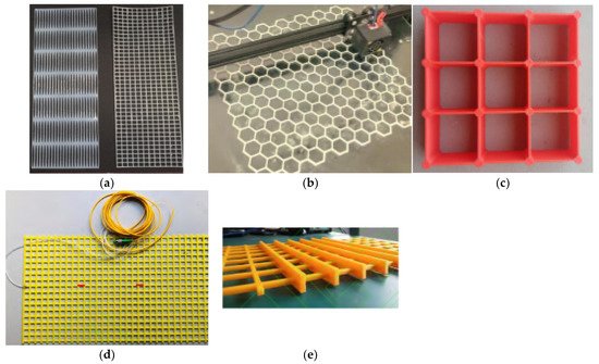
- 3D printing technologies can help optimize and construct small components of railway infrastructures, e.g., fastener components (clips, screw spikes and rail pads), geogrids and geocells.
- The rail can be enhanced by additive manufacturing technologies. The approach can help lengthen the life cycle of railway turnout systems by increasing the fatigue behaviour of rails (including stock rails, closure rails, wing rails and guardrails). With the development of new printable metallic and polymer materials, the rails can be fabricated with good mechanical properties using 3D printing technologies.
- 3D printing technologies have the potentials to be used in fabricating composite sleepers (bearers) with multi-layers and producing sleepers with complex shapes.
- 3D printed concrete technologies are well-developed and can be used to construct sound barriers in railway engineering. 3D printing concrete slab track is being prepared in the UK.
- Smart track detection methods can be developed using 3D printing technologies help to detect the track dynamic response in real-time.
The 3D printing technologies enable the fabrication of an ultra-high-speed tube track system (also called hyperloop), which allows the train to speed up to 1200km/h. Figure 16 indicates an initial conceptual design of the prototype hyperloop railway structure. Moreover, all-in-one track supports can be designed with a gradient density in accordance with the stress distribution inside the railway track support. The track stiffness is designable by changing the porosity and structural form of the all-in-one structures. The all-in-one track supports with gradient porosity will have a gradient track stiffness, which can help solve the problem of discontinuous stiffness in the transition areas.
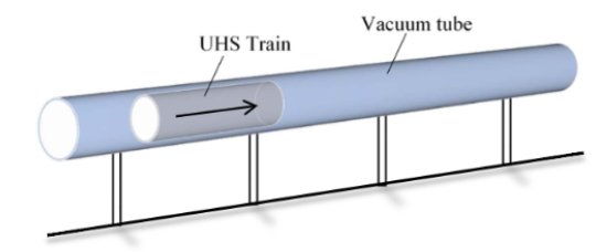
Figure 16. A conceptual design of hyperloop track system[142].
5. Conclusions
This paper presents an overview of 3D printing application and research in railway track infrastructures and the challenges and perspectives of 3D printed railway tracks. The main benefits of additive manufacturing technologies are fabricating complex objects, saving materials, reducing carbon emission, and shortening the product production cycle. The recent research and application of additive manufacturing (3DP) technologies in railway track infrastructures have been reviewed. Presently, the 3DP in railway infrastructures is still in the exploration stage; only the laser melting methods for enhancing rail and wheel surfaces are well developed. This is due to the poor reliability and other limitations of 3D printing technologies for railway engineering. However, 3D printing shows excellent prospects in building all-in-one track infrastructures and designing transition zone supports. In the future, with the development of 3D printing materials, technologies and standards, additive manufacturing will be adopted for building smart railway track infrastructures. This research can promote the research and application of 3D printing in railway engineering.
Author Contributions: Conceptualization, H.F. and S.K.; writing—original draft preparation, H.F.; writing— review and editing, H.F. and S.K.; graphics and visualization, H.F.; project administration, S.K.; funding acquisition, H.F. and S.K. All authors have read and agreed to the published version of the manuscript.
Funding: The research was partially funded by the China Scholarship Council and the European Commission for H2020-MSCA-RISE Project No. 691135 “RISEN: Rail Infrastructure Systems Engineering Network,” which enables a global research network that tackles the grand challenge in railway infrastructure resilience and advanced sensing under extreme conditions[143].
Conflicts of Interest: The authors declare no conflict of interest.