Geosynthetics have proven to provide sustainable solutions for geotechnical and geoenvironmental problems when used with natural materials. This study ("Sustainable Solutions with Geosynthetics and Alternative Construction Materials") addresses the use of geosynthetics with alternative construction materials in sustainable engineering solutions.
- geosynthetics
- wastes
- tires
- CDW
- PET bottles
1. Introduction
The preservation of the environment as a whole and specifically of its natural resources is of utmost importance for current and future generations. In this context, geosynthetics can provide sustainable engineering solutions for geotechnical and geoenvironmental problems, reducing the consumption of natural materials and causing less impact to the environment [1,2,3,4][1][2][3][4]. Geosynthetics can perform different functions in an engineering project, such as drainage, filtration, barrier, separation, reinforcement, and protection. Frischknecht et al. [1] showed reductions greater than 70% of some environmental impact parameters such as water consumption, renewable and non-renewable energy consumption, emissions of gases that contribute to global warming, etc. in some applications of geosynthetics in comparison with conventional geotechnical solutions. Significant reductions in energy consumption and CO2 2 emissions were obtained by Damians et al. [2] when the environmental impacts caused by geosynthetic reinforced retaining structures were compared to those from conventional concrete retaining walls. Heerten [3] also presented two examples of construction infrastructures where the use of geosynthetics showed lower environmental impacts due to significant reductions of cumulated energy demand and CO2 emissions. Touze-Foltz [4] presented several other examples of the environmental benefits of using geosynthetics in geotechnical and geoenvironmental works.
The benefits brought by the use of engineering solutions with geosynthetics discussed above were obtained using conventional soils as construction materials. When geosynthetics are combined with materials commonly considered wastes, solutions involving geosynthetics will be expected to be even more beneficial to the environment, since they will avoid or reduce the utilisation of good-quality natural materials (which are increasingly scarce and expensive in several regions) and reduce their exploitation, with positive repercussions for the environment. These are the cases of combinations of different geosynthetic products with wasted tires, plastic objects, and construction and demolition wastes, for instance. However, one must bear in mind that some of these wastes can be harmful to the environment. Thus, due care must be exercised when using wastes in construction to avoid ground contamination due to the degradation of the waste with time or the presence of pollutants. In this context, the use of such wastes may still be feasible if appropriate geosynthetic barriers (geomembranes or GCLs) are employed.
Very little can be found in the literature on the combination of geosynthetic products and alternative/waste construction materials in geotechnical and geoenvironmental works. The same comment applies to the use of wastes to produce low-cost alternative geosynthetics.
2. Some Combinations of Geosynthetics and Alternative Construction Materials
Some properties and characteristics of RCDW must be evaluated when considering the use of such material in geotechnical works. Below, some of these characteristics are described and discussed.
The degradation of aggregates and soils during shearing, when subjected to monotonic or cyclic stresses, has always been a concern for researchers and engineers even for natural materials such as decomposed granite soil [39][5], silica sand [40][6], and latite basalt [41][7]. When dealing with RCDW, this concern deserves special attention given that these materials present a very heterogeneous composition due to having different origins. According to Sivakumar et al. [42][8], cyclic direct shear tests on recycled aggregate revealed a reduction in friction angle due to particle crushing (from 43° to 38° for crushed concrete, and from 43° to 39° for crushed brickwork). Although special attention is needed for the construction and maintenance of some geotechnical works, the reported reduction in friction angle would not prevent the use of RCDW in most geosynthetic applications.
The reduction in ultimate tensile strength (T ult ) caused during the installation process has been pointed out as the most critical mechanism affecting the short-term durability of geosynthetics [54][9]. Besides the intrinsic characteristics of a geosynthetic (e.g., geometry, shape, and polymer) that affect its durability, the backfill material composition and installation procedures influence the occurrence and severity of damages. Bearing in mind the proposal of using RCDW in GRS structures, the damage mechanisms may be influenced by the physical and chemical characteristics of such new backfill material.
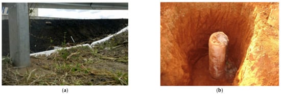
Alkhorshid [63][10] investigated the use of geosynthetic-encased columns (GEC) to reduce excessive settlements and failure of embankments built on soft soils ( Figure 71a,b). In this type of subgrade, there is low confinement at the upper part of the granular column, reducing its load capacity. A technique that has been applied to increase column lateral confinement is the use of geotextile encasement ( Figure 71b). Large scale tests were carried out by Alkhorshid [63][10] on conventional and geotextile-encased granular columns using a large box (1.6 m × 1.6 m × 1.2 m) to investigate the use of three types of woven geotextile encasements and three types of infill materials, including RCDW. The GEC models were 1000 mm in height and 150 mm in diameter. Sand, calcareous gravel, and recycled construction and RCDW were used as infill materials for the columns. Bentonite (4% in mass) was added to the subgrade soil to increase its plasticity and workability, resulting in a soft subgrade classified as CH by the Unified Soil Classification System (USCS). The properties of the soft soil and filling materials and the geotextile characteristics are presented in Table 41 and Table 52. If a scale factor of 4 is considered, the tests would simulate a prototype problem of a 0.6 m-diameter encased column in a soft clay with an undrained strength of 20 kPa. During the tests, monotonically increasing vertical loads were applied to the column top by a rigid steel plate.
| Property | Soil | |||
|---|---|---|---|---|
| Clay | ||||
| Property | RCDW | Tire Shreds |
|---|---|---|
| Sand | Gravel | RCDW |
| Liquid limit (%) | 60 | - | - | - |
| D | 90 | (mm) | 1 | 33 | ||
| Plasticity index (%) | 21 | - | - | - | ||
| Soil particle density (-) | 2.7 | 2.65 | 2.66 | 2.65 | ||
| Compression index | 0.47 | - | - | - | ||
| 45 | ||||||
| D | 85 | (mm) | 31 | --- | ||
| D | 50 | (mm) | 21.4 | --- | ||
| D | 10 | (mm) | 2.0 | --- | ||
| Expansion index | 0.03 | - | - | - | ||
| Undrained strength (kPa) | ||||||
| Coefficient of uniformity | ||||||
| 5 | - | - | - | |||
| 12.5 | 1.5 | |||||
| Dry unit weight (kN/m | 3 | ) | 11.13 | 3.67 | ||
| Coefficient of uniformity | 5.5 | 3.51 | 1.6 | 1.5 | ||
| Void ratio | 0.95 | 2.19 | ||||
| Coefficient of curvature | 1.05 | 0.825 | 0.98 | 0.92 | ||
| D | 50 | (mm) | 0.304 | 0.50 | 6.55 | 6.64 |
| Permeability (cm/s) | 2,3 | 10 | 15 | |||
| D | 10 | (mm) | 0.073 | 0.179 | 4.44 | 4.78 |
| D | 30 | (mm) | 0.175 | 0.305 | 5.56 | 5.64 |
| D | 60 | Maximum void ratio | - | 0.87 | 0.74 | 0.76 |
| Minimum void ratio | ||||||
| Compression index | 2 | |||||
| (mm) | 0.401 | 0.63 | - | 0.6 | 0.41 | 0.45 |
| 1.18 | 0.79 | |||||
| 7.11 | 7.21 | Friction angle (degrees) | - | 41 | 43 | 42 |
| Dilation angle (degrees) | - | 11 | 12 | 12 |
Table 52. Properties of the geosynthetic encasements.
| Property | Geotextile | ||
|---|---|---|---|
| G-1 | G-2 | G-3 | |
| Tensile strength (kN/m) | 30 | 16 | 8 |
| Maximum tensile strain (%) | 22 | 16 | 15 |
| Tensile stiffness (k/m) | 120 | 107 | 53.4 |
3. Combinations between Geosynthetics and Alternative Materials in Waste Disposal
Landfills have plenty of materials that can be reused in civil engineering works and to fulfil some needs of the landfills themselves. This section addresses some combinations of geosynthetics and waste materials for applications in landfills.
The water pluviation on the waste started 75 days after the waste disposal in the containers, under pluviation rates of 10 L/week to simulate wet seasons and 2.5 L/week to simulate dry seasons. The instrumentation used allowed the measurement of waste settlements and temperature in the waste mass below the geotextile filter and inside the drainage trench. Effluent volumes were collected for measurements of effluent flow rates as well as chemical analyses such as the determination of pH, chemical oxygen demand, sulphate content, ammonium content, nitrate content, and solids content. Additional information on materials and testing methodology can be found in Paranhos and Palmeira [77][11], Silva [78][12], and Palmeira et al. [79][13].
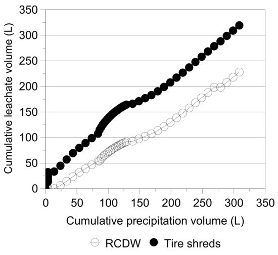
Figure 142 depicts the variation of cumulative effluent volume from the containers with the cumulative volume of precipitation. The results show a greater discharge capacity of the drainage trench with tire shreds in comparison with that of the RCDW aggregate. Some level of waste heterogeneity may have influenced the different responses of the drainage systems. However, even before the start of the water pluviation on the waste, effluent flow was already noticed in container C2, whereas effluent in container C1 only started after water pluviation. This late response from C1 may also be a consequence of the presence of the horizontal drainage layer in container C2, which was not present in C1, besides the large coefficient of permeability of the tire shreds (Table 83). It can also be noted that after 130 L of water pluviation (approximately 138 days since the beginning of pluviation) the rate of increase in the effluent volume with pluviation volume was very similar for both drainage systems.
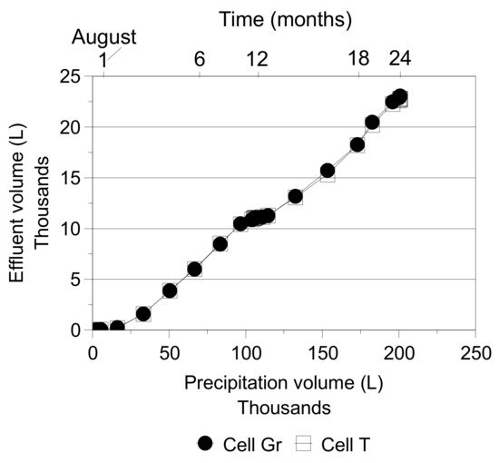
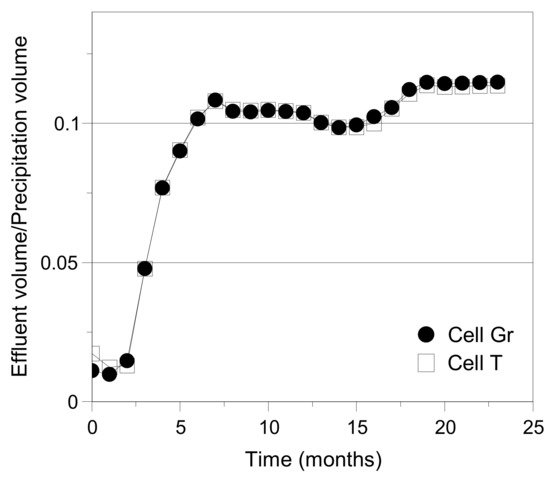
The variation of cumulative effluent volume with cumulative precipitation volume is presented in Figure 193. It can be observed that the results obtained are very similar, showing the good performance of the alternative drainage system in comparison with that of the conventional one. The rather constant value of effluent volume between months 7 and 14 corresponds to the dry season in the region. Hence, the response of the drainage systems in terms of effluent volumes was directly related to the pluviation in the region. Figure 204 shows the ratio between the effluent volume and the volume of water precipitated on the cells during rainy periods, showing again the similar behaviour of both drainage systems investigated. The rather constant rate between the effluent and precipitated volumes in the first three months of monitoring was due to fact that the initiation of flow took place during a dry season, thus with the effluent from both cells being mainly a consequence of the decomposition of organic matter. Junqueira et al. [16][14] showed that similar variations of settlement and chemical parameters of the effluent with time were also found for both cells. However, the amount of suspended solids in the effluent from cell T was smaller than that from cell Gr due to the filtering action of the geotextile layer in the former. For the duration of the experiment, there was no indication of clogging of the geotextile filter.
References
- Frischknecht, R.; Stucki, M.; Büsser, S.; Itten, R. Comparative life cycle assessment of geosynthetics versus conventional construction materials. Ground Engng. 2012, 45, 24–28.
- Damians, I.P.; Bathurst, R.J.; Adroguer, E.G.; Josa, A.; Lloret, A. Environmental assessment of earth retaining wall structures. Env. Geotech. 2017, 4, 415–431.
- Heerten, G. Reduction of climate-damaging gases in geotechnical engineering practice using geosynthetics. Geotex. Geomemb. 2012, 30, 43–49.
- Touze-Foltz, N. Healing the world: A geosynthetic solution. In Proceedings of the 11th International Conference on Geosynthetics, Seoul, Korea, 16–21 September 2018. 59p.
- Miura, N.; O-Hara, S. Particle-crushing of decomposed granite soil under shear stresses. Soils Found. 1979, 19, 1–14.
- Hyodo, M.; Hyde, A.F.L.; Arakami, N.; Nakata, Y. Undrained monotonic and cyclic shear behaviour of sand under low and high confining stresses. Soils Found. 2002, 42, 63–76.
- Indraratna, B.; Salim, W. Modelling of particle breakage of coarse aggregates incorporating strength and dilatancy. Proc. Inst. Civ. Eng. 2002, 155, 243–252.
- Sivakumar, V.; McKinley, J.D.; Ferguson, D. Reuse of construction waste: Performance under repeated loading. Proc. Inst. Civ. Eng. 2004, 157, 91–96.
- Hufenus, R.; Rüegger, R.; Flum, D.; Sterba, I. Strength reduction factors due to installation damage of reinforcing geosynthetics. Geotex. Geomemb. 2005, 23, 401–424.
- Alkhorshid, N.R. Analysis of Geosynthetic Encased Columns in Very Soft Soil. Ph.D. Thesis, Graduate Programme of Geotechnics, University of Brasilia, Brasilia, Brazil, 2017.
- Paranhos, H.; Palmeira, E.M. Alternative Low-Cost Drainage Systems for Geotechnical and Geoenvironmental Works; Research Report-RHAE/CNPq/UnB; Graduate Programme of Geotechnics, University of Brasilia: Brasilia, Brazil, 2002; 79p. (In Portuguese)
- Silva, A.R.L. A study on the Behaviour of Drainage Systems of Waste Disposal Areas under Different Scales. Ph.D. Thesis, Graduate Programme on Geotechnical Engineering, University of Brasilia, Brasília, Brazil, 2004; 329p. (In Portuguese).
- Palmeira, E.M.; Silva, A.R.L.; Paranhos, H. Recycled and alternative materials in drainage systems of waste disposal areas. In Proceedings of the 5th International Congress on Environmental Geotechnics, Cardiff, UK, 26–30 June 2006; Volume 2, pp. 1511–1518.
- Junqueira, F.F.; Silva, A.R.L.; Palmeira, E.M. Performance of drainage systems incorporating geosynthetics and their effect on leachate properties. Geotex. Geomemb. 2006, 24, 311–324.