Your browser does not fully support modern features. Please upgrade for a smoother experience.
Please note this is a comparison between Version 1 by Youping Gong and Version 2 by Jason Zhu.
To solve the mismatch between the comprehensive mechanical properties of the spinal fusion cage and body, a fusion cage inner hole design method based on controllable TPMS-P to characterize the inner hole structure is proposed to solve the related problems.
- Porous Structure
- Design
- Performance
1. Introduction
The spinal implant devices manufactured by the existing technology have obvious shortcomings, and the comprehensive mechanical properties of the solid metal implants do not match, resulting in a serious stress shielding effect between the solid metal implants and the host bone [1][2][1,2]. The ideal interbody fusion cage implantation device should have good biocompatibility, can complete the new bone growth in an effective time, and achieve real interbody fusion. In addition, the device located in the load-bearing position needs to have certain comprehensive mechanical properties. When constructing the implant model of the personalized interbody fusion cage, it is necessary to comprehensively consider the biomechanical properties, porosity, pore distribution, connectivity, and other factors of the fusion cage. The microporous structure design of the fusion cage is the key part of the process of spinal repair and replacement. In the design method of the porous structure model, the typical porous structure design method includes a computer aided design porous structure design method, based on the CT scanning image mapping porous structure design method and TPMS porous structure design method. The computer aided design porous structure design method is a combination of computer graphics and CAD program modeling, through the construction of solid geometry, to build a complex model. This method, as an attempt of the early design of the porous scaffolds, only carries out simple Boolean operations and arrays, and the parameters, such as porosity and gradient pores of the scaffolds, are poorly controllable. The method of model reconstruction based on medical images is generally through the analysis and processing of CT or MRI medical data images, using related algorithms to extract features of specific areas and 3D model reconstruction in professional software. According to the number of large-scale images of tibia under the DICOM standard, a clear bone microstructure image was obtained by using image binarization, thermal pixel removal, closure operation, and other algorithms, and then the perimeter and area of bone microstructure pores were measured by the straight line fitting method based on the least square method. Although the bone tissue 3D model reconstruction algorithm based on medical images can obtain structural and morphological features, and is similar to bone tissue, its implementation process is generally complex and requires high software algorithms, system hardware, and users. The implicit curved surface porous element construction method can effectively parametrically control the pore shape, pore size, specific surface area, porosity, and other parameters of the porous unit, which makes the mechanical and biological properties of the designed porous implant meet the ideal requirements, and has a positive impact on cell migration and tissue inward growth, which has attracted the attention of researchers [3][4][5][6][7][8][6,7,8,9,10,11]. The triply periodic minimal surface (TPMS), as a kind of implicit surface, has the advantages of a controllable parameter design and integrity of model expression, and has the advantages of ideal connectivity and controllability, which provides a new design method for the construction of existing porous implants [9][10][11][12,13,14]. The TPMS construction method can be used to construct a porous structure implant model with a linear change of pore structure. By regulating the pore structure, the pore structure of the porous implant changes linearly from the surface to the inside, so that the surface elastic modulus of the porous implant, in contact with bone tissue, is close to that of bone tissue.
The above studies show that the bone tissue microporous structure design based on the TPMS curved surface porous structure design method can optimize the mechanical properties of porous implants and can be used as the characterization of the inner pore structure of ideal bone implants. However, the following problems need to be solved: (1) at present, the microporous structure of TPMS bone tissue is generally constructed by only one kind of pore-forming element, even if two kinds of elements are used to construct the pore structure element, the boundary of the element is discontinuous and there is a phenomenon of local stress concentration. (2) The existing TPMS inner hole structure uses conventional finite element analysis to realize structure distribution topology optimization and gradient design, which cannot directly predict the comprehensive mechanical properties of the inner hole structure, and the simulation model has a large amount of data, which consumes a lot of computing resources in the follow-up simulation and optimization design process. In this paper, a design method of the porous structure based on parameterized TPMS is proposed. The three-dimensional periodic minimum surface method is used to further realize the correlation mapping between the structure and performance. Through the rapid optimization of the shape and spatial distribution of the micropore structure, the best match between the comprehensive mechanical properties of implant parts and defective bone tissue is realized.
2. Design and Performance Simulation Analysis of Porous Structure
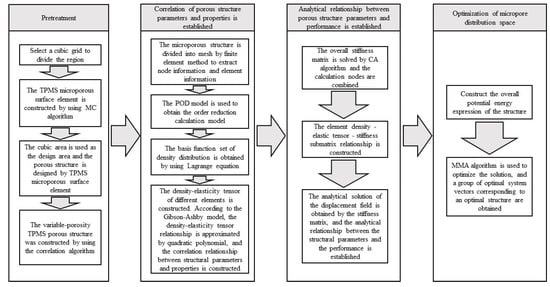
In the spinal bone, the pore sizes of different segments of the bone are different, and the distribution of the pore sizes are uneven. The optimal fusion cage bone implant should have similar mechanical and biological characteristics to the original spinal bone. It is of great significance to study how to optimize the spatial distribution of pore structure and pore structure in spinal implants. In this paper, through the construction method of TPMS, the implicit function equation model, the bionic porous structure model and the linear gradual porous structure model are constructed parametrically, and the pore shape, size, linear change rate, and other structural characteristics of the porous model are changed by adjusting the construction parameters of the model, to obtain the ideal porous structure implant parts [12][13][14][15][16][18,19,20,21,22]. The detailed design steps are shown in Figure 1.
Figure 1. TPMS pore structure parameters—performance mapping and pore structure spatial distribution optimization, comprehensive mechanical control process.
3. Study on the Performance of Porous Structure Simulation Model
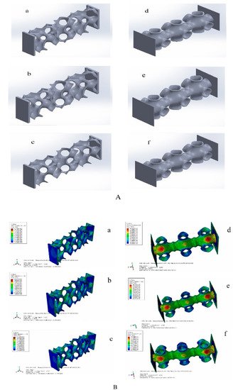
Through the above TPMS porous structure model design and spatial distribution optimization, the optimal TPMS porous structure solid model with variable pore sizes was obtained. To verify whether its mechanical properties meet the requirements, it is necessary to simulate and analyze its mechanical properties. Based on TPMS homogeneous porous structure modeling, TPMS porous structure units with corresponding porosity were mainly used to build. It is completed in Materialise Magics 21.0 software. The schematic diagram of the TPMS uniform porous structure model is shown in Figure 2A, where a, b, c, are, respectively, the G-TPMS model (a: G model 3 based on the TPMS non-uniform porous structure (hereinafter referred to as G-3); b: G model 2 based on the TPMS non-uniform porous structure (hereinafter referred to as G-2); c: G model 1 based on the TPMS non-uniform porous structure (hereinafter referred to as G-1); and where d, e, f, are, respectively, the P-TMPS model (d: based on the TPMS uniform porous structure P model 3 (hereinafter referred to as P-3); e: based on the TPMS homogeneous porous structure P model 2 (hereinafter referred to as P-2); f: based on the TPMS uniform porous structure P model 1 (hereinafter referred to as P-1)).


Figure 2. TPMS porous structure models and simulation results. ((A) (a: G model 3 based on the TPMS non-uniform porous structure; b: G model 2 based on the TPMS non-uniform porous structure; c: G model 1 based on the TPMS non-uniform porous structure; d: based on the TPMS uniform porous structure P model 3; e: based on the TPMS homogeneous porous structure P model 2; f: based on the TPMS uniform porous structure P model 1). (B) (a: the maximum equivalent stress of G-1 is 95.78 Mpa;b: the maximum equivalent stress of G-2 is 111.5 Mpa; c: the maximum equivalent force of G3 is 124.7 Mpa; d:the maximum equivalent stress of P-1 is 83.83 MPa; e: the maximum equivalent stress of P-2 is 84.36 MPa; the maximum equivalent stress of P-3 is 84.49 MPa)).
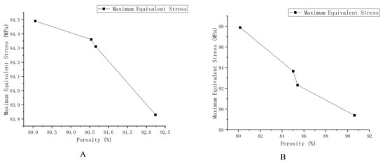
Considering that the TPMS porous structure entity is mainly used in the lumbar interbody fusion cage, mainly under pressure, this paper only carries on the corresponding compression simulation analysis. In this paper, the grid was divided by HyperMesh 14.0 software, and after the division was complete, it was imported into Abaqus 19.0 software for simulation analysis. The simulation parameters of material Ti6Al4V are as follows: density was 4.4 × 10⁹ kg/m3, Young’s modulus was 1.17 × 10¹¹ Pa, Poisson’s ratio was 0.342, and pressure was 2 × 10⁸ Pa. To facilitate the application of boundary conditions, planar entities are added to the upper and lower surfaces of TPMS porous solids. The results of the simulation analysis are shown in Figure 2B, where a, b, c, are, respectively, maximum equivalent stress (a: the maximum equivalent stress of G-1 is 95.78 MPa, b: the maximum equivalent stress of G-2 is 111.5 MPa, c: the maximum equivalent force of G3 is 124.7 MPa). RWesearchers can also calculate the porosity of the three porous structures respectively (G-1:86.3%, G-2:77.60%, and G-3:74.41%). Where d, e, f, in Figure 2, right side, are, respectively, d, e, f’s maximum equivalent stress (the maximum equivalent stress of P-1 is 83.83 MPa; that of P-2 is 84.36 MPa; and that of P-3 is 84.49 MPa). Moreover, reswearchers can obtain porosity of the three porous structures, respectively (P-1:92.24%, P-2:90.54%, and P-3 89.06%). ResearchersWe unify the maximum equivalent stress of two different TPMS structures with different porosities into a broken line diagram, as shown in Figure 3.


Figure 3. Schematic diagram of the maximum equivalent stress of different structures and different porosity. (A) The maximum equivalent stress of G structure with different porosity. (B) The maximum equivalent stress of the P structure with different porosity.
As shown in Figure 3, the results show that the maximum equivalent stress decreases with the increase of porosity and increases with the increase of loading force/pressure. The TPMS porous structure with variable pore sizes has a more appropriate maximum equivalent stress and porosity than the non-TPMS uniform porous structure and the TPMS-based uniform porous structure. Moreover, the TPMS-based uniform porous structure has a more appropriate maximum equivalent stress and porosity than the non-TPMS uniform porous structure. According to two related literatures [17][18][23,24], the porosity of 10–95% and the compression strength of 0.5–350 MPa can well meet the mechanical properties and medical needs, so the TPMS porous structure entity designed in this paper is reasonable, and it could overcome the current design defects of lumbar interbody fusion cage and help patients accelerate their recovery.
